ANALOG INPUTS
• High throughput; aggregate scan rates to 2 MHz
• Four sample-and-hold, differential analog input channels
• 12-bit analog-to-digital converter (ADC), with range options of 0 to +5 V and ±5 V, or 0 to +10 V to ±10V
• Simultaneous sampling of all inputs
• Dual 256 Kbyte data buffers
• Continuous or synchronous sequencing
• Multiboard or independent synchronizing
• Program-controlled bus interrupter
• No programming required in software transparent operating mode
• MTBF: 32,800 hrs. (217E)
ANALOG OUTPUTS
• Dual 12-bit (10 mA) analog outputs
• Output ranges of 0 to +10 V, ±5 V, and ±10 V
DIGITAL INPUT/OUTPUT
• Dual 8-bit TTL I/O ports, program controlled as inputs or outputs
GENERAL DESCRIPTION
The VMIVME-3115 is a high throughput ,12-bit Analog Input/Output (AIO) board which provides four analog inputs, two analog outputs, and dual 8-bit bi-directional digital input/output ports for VMEbus system applications.
Dual-ported data memory, on-board timers, and a program-controlled bus interrupter enables the VMIVME-3115 board to support extensive analog input and output traffic with minimum involvement of the host processor.
Sample-and-hold input amplifiers provide “snapshot” simultaneous sampling of all analog inputs at aggregate sample rates up to 2 MHz, and virtually eliminate time skewing between input channels. The VMIVME-3115 supports both independent and multiboard synchronization. Dual analog outputs enable the board to “close the loop” in system servo applications.
Analog input data is stored sequentially in dual 256 Kbyte buffer memories. The host controls which one of the two buffers will reside in VMEbus memory through a single toggle bit in the Control and Status Register (CSR). The host can also direct the board to generate an interrupt when a scanning sequence is completed.
Analog inputs can be sequenced either continuously, single block synchronously, or multiboard synchronously. In the continuous mode, sequencing executes
continuously until stopped by the host processor. In the single block synchronous mode, a preselected block of data is transferred, after which VMIC • 12090 South Memorial Parkway • Huntsville, Alabama 35803-3308 sequencing halts. Multiboard synchronization can be applied to either the continuous or single block modes, with a designated board controlling other VMIVME-3115 boards.
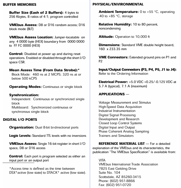
Each buffer memory appears as 256 Kbytes of VMEbus memory. To simplify automatic system configuring, the buffer is disabled during power up and reset operations. To support multiple VMIVME-3115 boards without requiring additional memory space, the buffer can be removed from the VMEbus memory entirely through a control bit in the I/O space CSR. The buffer is jumper locatable on any 4 0000 byte (HEX) boundary in the VMEbus memory space. Block Mode D16 data transfers (BLT) are supported.
Dual analog output channels can drive 10 mA loads over the maximum output range of ±10 V. On-line or off-line (disconnected) operation is program controlled. Each analog output is controlled directly by a single 16-bit word in the VMEbus short I/O space.
FUNCTIONAL CHARACTERISTICS
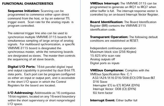
Sequence Initiation: Scanning can be programmed to commence either upon direct command from the host, or by an external TTL trigger event. Scan rate for the analog inputs is program controlled.
The external trigger line also can be used to synchronize multiple VMIVME-3115 boards for simultaneous sampling of large arrays of analog signals. For multiboard sychronization, a specific VMIVME-3115 board is designated the synchronous master, while the remaining boards
are designated as slaves. The master then controls the sequencing of all slave boards.
Digital I/O Ports: 16-bit parallel digital input and output capability is provided by dual 8-bit TTL
data ports. Each port can be program configured as either an input or output port, and is accessible in the short I/O space in which the Control

Registers for the board are located.
I/O Addressing: Addressable as 16 contiguous 16-bit registers, located on any 16-word boundary
within the short supervisory or short nonprivileged I/O space.
Memory Addressing: The Analog-to-Digital Converter (ADC) buffer appears as conventional
memory to the VME host. Total memory space occupied by the board is 256 Kbytes, and can be program located on any 4 0000 byte (HEX) boundary in the VMEbus memory space. The
VMIVME-3115 buffers can be removed (masked) from VMEbus memory by a CSR control bit.
I/O Address Selection: Board address in the short I/O space is selected by on-board field
selectable jumpers. Operation is supported in any slot except slot 1.
Access Privilege: Address modifiers are decoded to support either supervisory, nonprivileged, or both accesses. Jumpers are provided to support this feature, and are factory configured for either access. Decoded modifier codes include 09, 0A, 0B, 0D, 0E, 0F, 2D, 29, 39, 3A, 3B, 3D, 3E, and 3F.
VMEbus Interrupt: The VMIVME-3115 can be programmed to generate an IRQ1 to IRQ7 when
either buffer is full. The interrupt response vector is controlled by an on-board Interrupt Vector Register.
Board Identification: The Board Identification Register (BIR) contains the VMIVME-3115 identification code.
Transparent Operation: The following default conditions are established at RESET:
Independent continuous operation
Maximum block size (256 Kbytes)
15.625 kHz scan rate
Analog outputs off
Digital ports as inputs
VMEbus Compliance: Complies with the VMEbus Specification Rev. C.1
A32/A24/A16:D16/D08 (EO) DTB Slave:BLT
D16 Slave
Interrupter I(1) to I(7) ROAK (DYN)
Interrupt Vector: D08 (O) (DYN)
6U form factor
Interrupt Event: Either buffer full
ELECTRICAL SPECIFICATIONS AT 25 °C
Analog Inputs:
Number of Input Channels: Four differential channels; jumper-selectable
Converter Channels: Two Sample-and-Hold Amplifiers: Eight (two per input
channel)
Resolution: 12 bits
Voltage Ranges: 0 to +5 V, ±5 V (options X-0-X and X-2-X), or 0 to +10 V, ±10 V (options X-1-X and X-3-X)
Input Sampling: Simultaneous sampling of all analog inputs
Interchannel Phase Skew: Less than 0.1°at 20 kHz
Scan Rate(1): Program controlled from 15.625 kCPS to 2 MCPS. See the Ordering Information.
Acquisition Time: Same as conversion cycle. .
Conversion Cycle (Settling Plus Conversion):1 m sec x 2,000,000/SCAN RATE. See Note 3.
Data Coding: Two’s complement, binary or offset binary
Gain Error: ±0.05 percent maximum
Input Offset: ±5 mV maximum
Input Impedance: 4 kW, differential; 8 kWwith 10 V input options
Input Protection: ±25 V; ±40 V with 10 V input options
Maximum Sampling Rate: 1.0 MCPS (2 channels) or 0.5 MCPS (4 channels), jumper-selectable
Common-Mode Rejection: 72 dB at 1 kHz; differential mode
Common-Mode Range: ±10 V (options X-0-X and X-2-X)±20 V (options X-1-X and X-3-X)
Crosstalk Rejection: 72 dB at 1 kHz
Analog Outputs:
Number of Output Channels: Two independent analog outputs
Resolution: 12 bits
Monotonicity: 12 bits, over operating temperature range
Output Modes: On-line (outputs connected to I/O connector) or off-line (outputs disconnected from I/O connector)
Voltage Ranges: 0 to +10 V, ± 5 V, ± 10 V, jumper-selectable
Output Impedance: Less than 0.5 W
Data Coding: Two’s complement, binary, or offset binary
Settling Time: 25 ms maximum, to 0.02 percent
Linearity Error: ±0.03 percent maximum
Output Offset: ±5 mV maximum
Load Current: ±10 mA maximum, over full output range of ±10 V
Load Capacitance: 5,000 pFd, no oscillation
Output Protection: Continuous short to ground; ±25 V for one second
Off-line Output Leakage: 50 nA maximum
1.MCPS = Million Channels per Second; kCPS = /Thousand Channels per Second
2. Each input is “pipelined” with two Sample-and-Hold amplifiers. Sample acquisition occurs while the previously acquired sample is digitized.
3.An effective conversion cycle of 500 ns (2 MCPS) is obtained by digitizing two channels simultaneously
Leave a comment
Your email address will not be published. Required fields are marked *