The user manual for Siemens SIMATIC TI505/TI500 series MODNIM (Modbus Network Interface Module) introduces the installation configuration, communication protocol, functional instructions, and diagnostic maintenance of the module. It supports both ASCII/RTU transmission modes, covers 17 core Modbus function codes, adapts to 50-19200 bps baud rates, and can set network addresses (1-247) and communication parameters through dip switches. It has functions such as power on self-test and runtime diagnosis, and can achieve master-slave data exchange between PLC and Modbus network. It is suitable for point-to-point or multi-point connection scenarios in industrial automation.
Module Core Overview
1. Basic information
Module models: PPX: 505-5184 (TI505 series), PPX: 500-5184 (TI500 series)
Core positioning: Modbus network interface module, realizing bidirectional data transmission between SIMATIC TI series PLC and Modbus network
Network architecture: master-slave network, supporting 1 master node+up to 247 slave nodes, supporting point-to-point or multi-point connection topology
Power requirement: Get+5 VDC power supply from the I/O dock, maximum power consumption 8 W
2. Key specifications
Category Core Parameter Details
Communication interface RS-232-C/423 2 communication ports (A/B), DTE configuration
15 selectable baud rates ranging from 50-19200 bps, set via dip switch
Either ASCII/RTU transmission mode, which requires the unified mode of the whole network
The verification methods LRC (ASCII) and CRC (RTU) are automatically calculated to ensure data integrity
Address range 1-247 0 is a broadcast address, 248-255 is invalid
Environmental conditions Working temperature 0-60 ℃ Relative humidity 5% -95% Non condensing, anti electromagnetic interference
Installation and Configuration
1. Installation process
Pre requirement: Disconnect the power supply of the I/O base, check that the module is not physically damaged, and wear an anti-static wristband
Installation steps:
Set up dip switch (address+communication parameters)
Insert the corresponding model I/O slot (TI505 single slot, TI500 dual slot)
Tighten panel screws (torque 0.3-0.6 N-m)
Connect communication cables to power supply
Key note: TI500 series requires installation of slot keys to prevent accidental insertion of other modules
2. Configuration of dip switch
Details of the configuration of the dialing group function
8-bit address dialing set network address binary encoding, address range 1-247 (0 and 248-255 disabled)
10 bit communication dial-up 1-4 baud rate selection, 4-bit combination corresponding to 15 baud rates (50-19200 bps)
10 digit communication dialing code, 5 stop bits, left=1 digit, right=2 digits
10 bit communication dial code 6-7 parity check dial code 6 left=enable check, dial code 7 left=even check/right=odd check
10 bit communication dial-up with 8 transmission modes: left=ASCII, right=RTU
10 bit communication dial-up 9 handshake protocol left=disabled, right=enabled RTS/CTS (adaptive modem)
10 bit communication dial code, 10 memory selection, left=C control relay, right=Y output coil
3. Wiring specifications
Cable requirements: 26 AWG tinned stranded copper wire with aluminum foil+65% braided shielding, PVC outer sheath (UL 30V/60 ℃)
Interface standard: RS-232-C 25 pin D-type connector, supporting three connection methods: no handshake/handshake/modem
Recommended cables: 9-pin crossover cable (P/N: 2601094-8001), 25 pin crossover cable (P/N: VPU200-3605)
Pin definitions: 2=TXD, 3=RXD, 4=RTS, 5=CTS, 7=signal ground, 20=DTR
Modbus communication protocol
1. Comparison of transmission modes
Characteristic ASCII mode RTU mode
Data bits 7 (hexadecimal printable) and 8 (binary)
Verification method LRC (Vertical Redundancy Check) CRC (Cyclic Redundancy Check)
Frame separator start character “:”+end character “CR/LF” 3.5 character silence time
Low transmission efficiency and high efficiency
Applicable scenarios: Low noise environments, industrial complex interference environments
2. Core function codes (17 types)
Function code, function description, maximum number of operations for operating objects
01 Read coil status Y/C coil 2000 pieces
02 Read input status discrete input X 2000
03 Read and hold register V variable memory 125
04 Read Input Register WX Word Input 125
05 Write a single coil Y/C coil 1 (supports broadcasting)
06 Write a single register V variable memory 1 (supports broadcasting)
07 Read 8 status coils inside the abnormal state-
08 Perform diagnostic module self-test/counter reset, etc-
11. Obtain communication event counter, successful message count-
Retrieve the communication event log for the last 64 events-
15 write multiple coils Y/C coils 800 (supports broadcasting)
16 write multiple registers V variable memory 100 (supports broadcasting)
Report 17: Station ID, PLC model/operating status, etc-
3. Abnormal response
Exception identifier: Function code highest position 1 (e.g. 01 → 81)
Core Exception Codes (8 types): 01 (Illegal Function), 02 (Illegal Address), 03 (Illegal Data Value), 04 (Associated Device Failure), 06 (Memory Parity Error), etc
Response mechanism: No response in broadcast mode, single address request returns exception code+checksum
Diagnosis and maintenance
1. Diagnostic testing
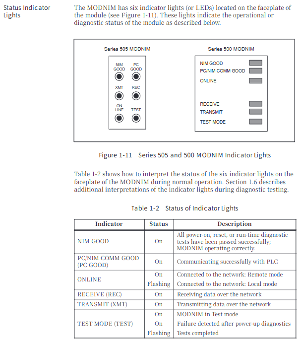
Power on self-test: After the module is powered on or reset, it checks the RAM/ROM/processor. If it passes, the NIM GOOD light will turn on
Run time diagnosis: Continuously monitor ROM integrity, PLC communication, watchdog timer, and enter offline mode if there is a fault
User triggers self-test: disconnect network cable → connect loop connector → reset+long press test button for 5 seconds, determine fault through LED status
LED status indicator: 6 LEDs (NIM GOOD/PC GOOD/ON LINE/REC/XMT/TEST), providing intuitive feedback on module status
2. Maintenance tools and operations
MODASST software: DOS environment configuration diagnostic tool, supporting communication parameter settings, function code testing, and troubleshooting
Module reset: Press the reset button to initialize the module, clear the counter and buffer
Firmware version: Supports reading software versions (Release 1.0-3.0) through function code 17
Replacement process: Power off → Pull out old module → Set new module dip code → Insert base → Power on self-test
3. Environment and Protection
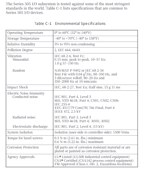
Working environment: temperature 0-60 ℃, humidity 5% -95%, non condensing, pollution level 2
Anti interference capability: compliant with IEC 801 standard, anti-static 15 kV, radiation interference level 3
Protection certification: UL 508, CSA 142, FM Class I Div. 2 certification
Leave a comment
Your email address will not be published. Required fields are marked *