The SIMATIC TI505/TI500 MODNIM User Manual (order number PPX: 505-8122-1) is a full process guide for the PPX: 505-5184 (TI505 series) and PPX: 500-5184 (TI500 series) Modbus network interface modules. The core covers four modules: installation configuration, Modbus protocol parsing, functional instruction description, and troubleshooting. It supports two ASCII/RTU transmission modes, 15 core Modbus function codes, and adapts to 50-19200 bps transmission rates. The network address (1-247) and communication parameters need to be configured through dip switches, and module debugging can be achieved with MODASST diagnostic software. It is suitable for Modbus master-slave network communication between PLCs and hosts in industrial environments.
Module core features
Category specific parameters/characteristics remarks
The TI505 series (1 I/O slot) and TI500 series (2 adjacent I/O slots) require dedicated slot keys to prevent accidental insertion
Communication interface dual RS-232-C/423 ports (A/B ports, redundant design) support DTE configuration, optional RTS/CTS handshake
Transmission mode ASCII mode and RTU mode are required to be unified throughout the network, which can be selected through the dial switch
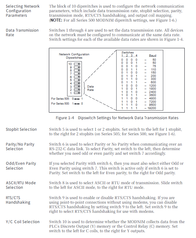
transmission rate 50、75、110、150、200、300、600、1200、1800、2400、3600、4800、7200、9600、19200 bps There are 15 options available, and the overall network speed must be consistent
Network addresses 1-247 (binary dialing setting) 0 and 248-255 are invalid addresses and will trigger test mode
Environmental adaptation: Operating temperature range of 0-60 ℃, storage temperature range of -40-70 ℃, humidity range of 5% -95% (non condensing), in compliance with industrial certifications such as UL508 and CSA142
Power consumption is taken from the base, with a maximum of 8W (+5VDC). The installation screw torque is 0.3-0.6 N-m
Core operating procedures
1. Installation and configuration
Preliminary preparation:
Module processing: Anti static packaging is required for transportation, conductive pads and grounding wristbands are needed in the work area, and the module should be checked for physical damage
Dial switch configuration (core steps):
Address dip code (8 digits): Set the unique network address from 1-247 in binary format (e.g. address 25 corresponds to 00011001)
Communication parameter dialing (10 bits): including rate (1-4 bits), stop bit (5th bit), parity check (6-7 bits), transmission mode (8th bit), handshake switch (9th bit), coil type (10th bit, Y output/C coil)
Module installation:
TI505 series: Insert into a single I/O slot, tighten the upper and lower screws to ground
TI500 series: Insert two adjacent slots and lock them with a dedicated key to prevent accidental insertion
Cable connection:
Recommended cable: Siemens standard 9-pin/25 pin null modem cable (order number 2601094-8001/VPU200-3605)
Self made requirements: 26 AWG tinned stranded wire+shielding layer, 25 pin D-type connector (gold-plated contacts)
Connection method: Supports two scenarios: module host (with/without handshake) and module commercial modem (with handshake)
2. Modbus protocol and functional instructions
Transmission frame structure:
ASCII mode: starting with “:” and ending with CR/LF, containing address (2 characters), function code (2 characters), data (n × 2 characters), LRC checksum (2 characters) fields, 7 data bits
RTU mode: Divided by 3.5 character mute frames, including address (1 byte), function code (1 byte), data (n bytes), CRC check (2 bytes) fields, and 8-bit data bits
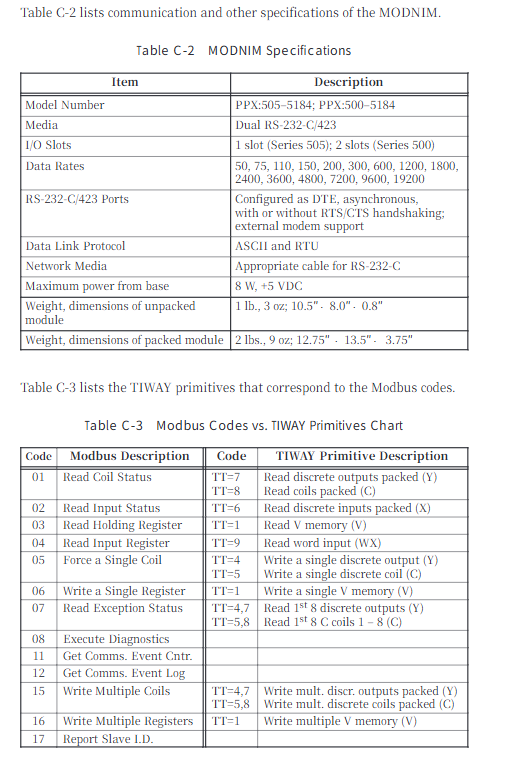
Core function codes (15 types):
Function Code Function Description Key Limitations
01 Read the status of up to 2000 coils
02 Read input status with a maximum of 2000 discrete inputs
03 Read and hold registers with a maximum of 125 registers
04 Read input registers up to 125 registers
05 Writing a single coil supports broadcast mode (no response)
06 Writing to a single register supports broadcast mode (no response)
07 reads abnormal status and only returns the status of the first 8 coils
08 diagnostic execution includes 14 diagnostic codes (such as circuit testing, counter reset)
11. Obtain the communication event counter return status word+event count
Retrieve communication event log and return status word+count+64 event bytes
Write multiple coils with a maximum of 800 coils and support broadcasting
Write to multiple registers with a maximum of 100 registers and support broadcasting
Report 17 returns information such as PLC model and operating status from the station ID
Address mapping rules:
Modbus address starts from 0, SIMATIC TI PLC address starts from 1, attention should be paid to address offset adaptation in the program
Coil mapping: Y discrete output of PLC or C control relay can be selected (by dialing the 10th digit)
3. Diagnosis and maintenance
Self checking function:
Power on self-test: After the module is powered on or reset, it automatically tests the ROM, RAM, and processor, and indicates the status through NIM GOOD/PC GOOD LED
Run time self-test: monitor ROM integrity, PLC communication, watchdog timer in the background, and enter offline mode in case of failure
User initiated self check: Disconnect the network cable, connect the circuit connector, press and hold the RESET+TEST button for 5 seconds, and determine hardware/port faults through LED status
Status indication (LED function):
LED name status meaning
NIM GOOD is always on: the module hardware is normal; Extinguish: Hardware malfunction
PC GOOD is always on: communication with PLC is normal; Extinguish: Communication failure
ONLINE always on: remote mode; Flashing: Local mode (only supports read function)
REC/XMT constantly on: receiving/sending data
TEST constantly on: self-test failed; Blinking: Test completed
MODASST software assistance:
Function: Configure communication parameters, generate dialing diagrams, cable pin diagrams, run diagnostics, send test instructions
Operating environment: IBM compatible with PC and DOS systems, requiring RS-232-C null modem cable connection module
Troubleshooting and Exception Handling
Common faults and solutions:
Core causes of fault phenomena and solutions
The module cannot log in to the PLC. The I/O address is not registered and the module is not securely plugged in. Use a programming device to read the I/O mapping, re plug and unplug the module, and tighten it
Communication failure rate/mode/verification mismatch. Check the communication parameters of all network devices and reconfigure dialing
Self check TEST light is constantly on due to hardware malfunction (ROM/RAM/port). Perform user initiated self check and contact after-sales service after confirming the fault
The write function failure module is in local mode. Switch the Local/Remote switch to Remote mode
Exception response code (core):
Reason corresponding to the meaning of the exception code
01 Illegal function request function code not supported
02 Illegal data address request address exceeds PLC memory range
03 Illegal data value written data exceeds the allowed range
04 Failed to associate device. PLC did not respond or instruction was aborted
06 Memory Parity Error Detected parity error while reading memory
Leave a comment
Your email address will not be published. Required fields are marked *