The SIMATIC RF120C Communication Module Operation Guide introduces the application scenarios, installation and connection, configuration parameter allocation, service maintenance, and technical data of the module. It is suitable for SIMATIC S7-1200 controllers (firmware ≥ 3.0) and can be connected to one RFID or optical reader through RS422 interface. It supports a maximum transmission speed of 115.2 kbps and a maximum cable length of 1000m, with a protection level of IP20. It needs to be configured with TIA Portal (STEP 7 V13 and above) and can achieve functions such as reading, writing, and addressing of the responder. Only qualified professionals are allowed to operate it.
1. Product Overview
(1) Application Fields and Core Features
Category key information
Applicable scenarios with SIMATIC S7-1200 controller to achieve data exchange between RFID/optical readers
Compatible with RF200/RF300/RF600 (RF620R/RF630R), MV400/MV500, MOBY D/U series readers
Core feature: 1 RS422 interface, supporting 1 reader connection; Protection level IP20; A single S7-1200 can accommodate up to 3 RF120Cs; Support standard addressing (linear address access)
Software requirements include TIA Portal (STEP 7 Basic/Professional V13 and above), integrated with Ident library and function blocks
(2) Installation and configuration requirements
Installation position: Adjacent to the left side of S7-1200, with a ventilation gap of 25mm above and below
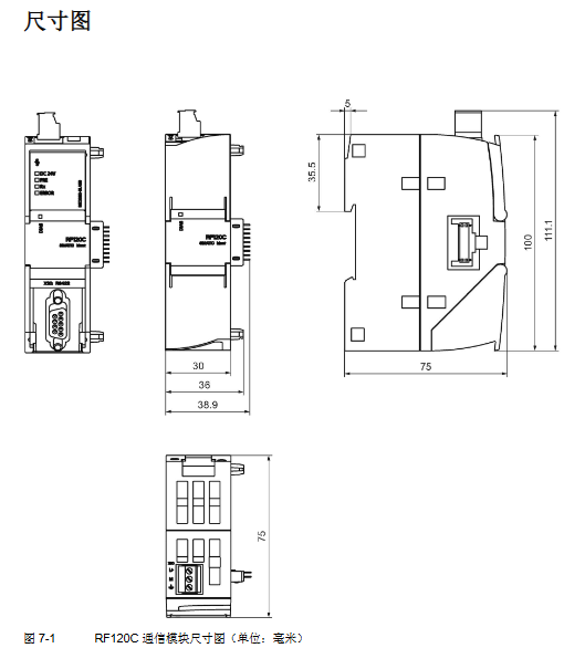
Installation method: 35mm DIN rail installation, width 30mm, weight 0.15kg
Temperature range: Horizontal installation 0 ° C~55 ° C, vertical installation 0 ° C~45 ° C
2. Installation and Connection
(1) Safety Notice
Power requirements: Safety ultra-low voltage (SELV/LPS), compliant with IEC 60950-1/EN 60950-1/VDE 0805-1
Operation specifications: Power off installation/disassembly, prohibit opening the equipment when powered on; 24V power supply needs to be protected against electromagnetic pulses (such as lightning protection)
Grounding requirement: The module needs to be grounded through the shielding layer
(2) Installation and connection steps
Remove the left bus cover of the S7-1200 CPU, align the RF120C bus connector, and snap it in
Install the CPU and RF120C onto the DIN rail and secure them in place
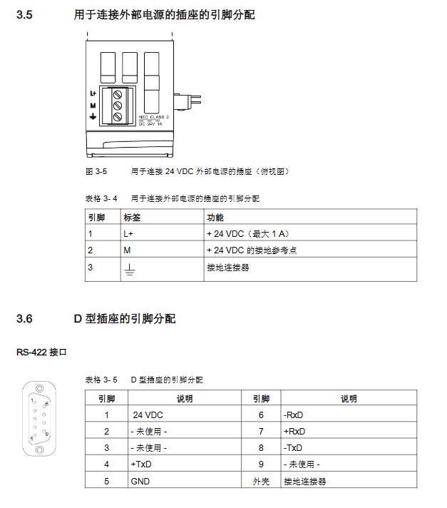
Connect an external 24V power supply to the top 3-pin socket of RF120C
Connect the reader to the RF120C 9-pin D-type female connector via a D-type cable
Connect the power, close the module front cover, download STEP 7 project data to complete debugging
(3) Power supply and pin allocation
Interface Type Pin Configuration Function Description
External power socket (3-pin) 1-pin (L+):+24VDC (maximum 1A); 2-pin (M): Grounding reference; 3-pin: The grounding connector supplies power to the reader, automatically shuts off and notifies the CPU when overloaded
D-type socket (9-pin, RS422) pin 1: 24VDC; 4 legs:+TxD; 5 pins: GND; 7-foot: – RxD; 8 legs:+RxD; 9-pin: – TxD realizes data transmission with the reader, supports hot swapping
3. Configuration and parameter allocation
(1) Hardware configuration
Configuration path: TIA Portal → Project View → Add S7-1200 → Hardware Catalog → SIMATIC S7-1200 → Communication Module → Identification System → RF120C
Core limitation: Each S7-1200 can be configured with up to 3 RF120C modules
(2) Key parameter group
Explanation of default values for parameter group core settings
Reader parameter group diagnostic message, Ident device/system selection hard error, Ident configuration file selection of connected reader type, triggering hardware diagnostic alarm
Ident device/system parameter group transmission speed, presence check, RF power, transmitter responder type 115.2 kBd, on, 1.00W transmission speed support 19.2/57.6/115.2 kBd; RF power of 0.50~5.00W (depending on the reader)
Reader type parameter group (RF600 only) includes wireless configuration file, multi tag mode, intelligent single tag mode ETSI, UID=EPC-ID, and support for ETSI/FCC/CMIT wireless standards; Multi label mode with optional EPC-ID (8 bytes) or Handle-ID (4 bytes)
(3) Programming and Addressing
Programming method: Program through the Ident instruction of the S7 controller, using function block libraries (Read/Write/Read_SPC-ID, etc.)
Addressing rule: Linear addressing, from the starting address (such as 0x0000) to the ending address, automatically identifying the storage size of the sending responder
Typical address space: RF200 (ISO 15693) starting address 0x0000, ending address 0x002B (44 bytes); RF300 (20 byte EEPROM) starting address 0xFF00, ending address 0xFF13
4. Service and Maintenance
(1) LED status display
Meaning of LED type status
DIAG (red/green) green constant light configuration successful, no errors
DIAG (red/green) flashing green startup/not configured/firmware update
DIAG (red/green) module with constant red light is faulty and needs to be replaced
The LED inside the shell is green (DC 24V), and the external 24V power supply is normal
The yellow LED (Rx) inside the casing is communicating with the reader
There is an error in the red flashing (ERROR) of the LED inside the casing, and the number of flashes corresponds to the type of error
(2) Diagnosis and Error Handling
Diagnostic methods: LED status viewing, TIA Portal online diagnosis, GET-DIAG instruction evaluation, ERROR/STATUS parameter analysis
Error message structure: Status parameter 4 bytes (byte 0: function number; byte 1: error number; byte 2: error code; byte 3: warning)
Common errors: Reader unresponsive (ERROR flashes 3 times), voltage interruption/short circuit (flashes 17 times), parameter allocation error (flashes 21 times)
(3) Module replacement
Configuration storage: RF120C configuration data is stored in S7-1200 CPU
Replacement process: Power off → Disassemble old module → Install new module → Power on → CPU automatically issues configuration data without reloading the project
5. Technical data and appendices
(1) Core technical parameters
Category specifications
Electrical parameters: Power supply voltage of 20~30VDC (rated 24VDC); Backplane bus current consumption 110~250mA; maximum external power supply 1A
The maximum transmission speed of communication parameters is 115.2 kbps; The maximum cable length is 1000m (depending on the reader); Maximum block length of 240 bytes (non cyclic)
Mechanical parameter size 30 × 100 × 75mm; Material Xantar MX 1094 (Ti Grey 24L01); MTBF (40 ° C) 196 years
Environmental parameter storage temperature -40 ° C~70 ° C; anti static discharge 8kV (air)/4kV (contact)
(2) Compliance and ordering data
Certification standards: CE, FCC, cULus, KCC, RoHS (2011/65/EU), ATEX/IECEx explosion-proof certification
Core order number: RF120C module (6GT2002-0LA00); 2m connecting cable (6GT2091-4LH20); Terminal block (6GK5980-1CB00-0DA5)
Leave a comment
Your email address will not be published. Required fields are marked *