Document Overview and Core Positioning
Document property
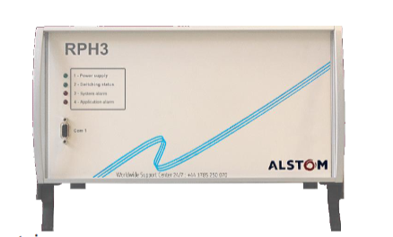
This manual is the service manual for the RPH3 “Point on Wave (PoW)” controller, which is used to guide the synchronous switching operation of high-voltage switchgear and support equipment understanding, installation, use, and maintenance.
Copyright belongs to GE Grid Solutions. The content is informative and can be adjusted according to technical and commercial needs. Unauthorized reproduction and disclosure are prohibited.
Reference architecture
GE internal documents: such as D1621EN (User Manual), D1622EN (RPH Manager Software Manual), etc.
International standard: Following IEC 62271-302 (Non synchronous pole operation of high-voltage switchgear).
Industry Report: Cited from CIGR É 262-264 publication (HVAC Switchgear Control Switching Guide).
Safety and Operation Instructions
Static Electricity and Electrical Safety
Electrostatic discharge (ESD) may damage equipment and should comply with anti-static standards such as EN 61340-5-1.
Power off before operation, confirm that the power supply voltage is compatible (AC 100-240V or DC 48-353V), only qualified engineers can operate.
Storage and installation requirements
Store in a dust-free and dry environment at -40 ℃~+70 ℃, with moisture-proof bags retained; Installed in the control room or relay room, ensuring good grounding, away from vibration sources, supporting 19 inch rack or wall mounted installation.
Principle of PoW Switching Technology
Random switching vs synchronous switching
Random switching: When the coils are powered on simultaneously, it is easy to generate surge current and overvoltage, which can cause equipment aging or protection misoperation.
PoW switching: By delaying the control of coil energization time, the high-voltage contacts are made to contact at the target point of the voltage waveform (such as zero crossing or peak), reducing transient phenomena. For example:
Inductive load (transformer) closing selects peak voltage to reduce excitation inrush current;
Capacitive load (capacitor) closing selects voltage zero crossing to reduce charging current surge.
Key parameters and terminology
Pre arming Time: The current conduction time before the mechanical contact of the contacts during closing, influenced by the dielectric strength decay rate (RDDS).
Operating Time: The time it takes for the coil to be powered on until the contacts fully move, and it is necessary to compensate for the effects of environmental temperature, hydraulic pressure, and other factors.
Adaptive Control: Based on historical operational data, adjust control timing and compensate for unpredictable factors such as equipment aging.
RPH3 Hardware and Functional Architecture
Module composition
M1: Power module, providing internal DC power supply.
M2: Central processing and communication module, integrated with DSP and Linux system, supporting Ethernet and fiber optic communication.
M3: Analog acquisition module, sampling reference voltage, current, temperature, hydraulic pressure and other signals.
M4: Signal and coil drive module, processing switch commands and relay outputs.
M5: Front panel management module, controls LED indicator lights and serial communication.
Core functional modules
Reference voltage sampling: Obtain the grid voltage through VT as a timing reference, supporting L1/L2/L3 phase selection.
Neutral point mode detection: supports hardware jumpers (M4-J5) or software settings to distinguish between grounded, isolated, or unknown modes.
Coil driver: Supports common mode/differential mode wiring, outputs 80ms adjustable pulses, and drives the opening and closing coils of switch devices.
Operation time measurement: Detect contact action through auxiliary contacts or current transformers (CT) with an accuracy of ± 0.1ms.
Compensation mechanism and adaptive control
Compensation factors for operation time
Environmental temperature: Low temperature will prolong operation time. Real time compensation can be achieved through a temperature sensor (4-20mA input), and the compensation meter can be configured through Web MMI.
Control voltage: Voltage fluctuations affect the rate of rise of coil current. The compensation value is calculated using the formula Δ t voltage=(U meas U rate − 1) ⋅ kU ⋅ t OP_rated, where kU is the compensation coefficient (to be measured).
Hydraulic pressure: For hydraulic drive mechanisms, real-time sampling is carried out through pressure sensors, and compensation is made according to Δ t pressure=(P meas P rate − 1) ⋅ kP ⋅ t OP_rated.
Idle time: Devices that have not been operated for a long time will slow down, compensated by the exponential function Δ t idle=A ⋅ (1 − e − BT idle), where A and B are empirical parameters.
Adaptive control is based on historical operational data and utilizes Δt adapt=K⋅(t measured −t commissioning −Δt compensations)+(1−K)⋅Δt adapt_prev Adjust the prediction time series, with K as the weight factor (default 0.3).
Alarm and Data Management
Alarm Type
System alarm: such as abnormal power supply, hardware failure, calibration failure, etc., triggering the red LED “3” on the front panel.
Application alarm: If the reference voltage exceeds the limit, the operation time is abnormal, the compensation value exceeds the limit, etc., the LED “4” will be triggered.
Relay output: 5 relays (1 monostable+4 bistable), which can be configured with alarm correlation logic through Web MMI.
Data recording and communication
Real time data: View parameters such as voltage, current, temperature, etc. through Web MMI, with a refresh rate of 3 seconds or 20 seconds.
Switching record: Stores the last 1025 operation data (“*. arch” file), supports downloading waveforms and event logs through RPH Manager software.
Network interface: Supports IP network (default IP 192.168.5.2), compatible with IEC 61850-9-2 communication protocol.
Application scenarios and switching strategies
Typical load switching scheme
Transformer/Three core Reactor:
Closing: Select the peak voltage (90 ° electrical angle) for the grounding neutral point, and select 0 ° or 180 ° for the isolation neutral point.
Trip: Select the current zero crossing point (corresponding to the peak voltage) to reduce overvoltage.
Single core reactor: The closing target point is the same as the transformer, and the tripping strategy is consistent.
capacitor:
Closing: Select voltage zero crossing (0 °) for the grounding neutral point and phase voltage zero crossing for the isolation neutral point.
Trip: Select the zero crossing point of the current to avoid heavy impact.
Transmission line:
Inductive VT: select voltage zero crossing for closing;
Capacitive VT: It is necessary to evaluate the residual charge in the circuit and select the peak voltage for closing.
Inductive load with NGR: Select the neutral point mode based on the inductance ratio r=LL N, and use a custom switching program when r ≥ 0.3.
Switch program configuration
Built in preset programs (transformers, reactors, capacitors), supporting user-defined modes (User Mode), can adjust the angle offset of each phase.
Technical parameters and specifications
Physical characteristics: 19 inch 4U rack, dimensions 483 × 177 × 452mm, protection level IP20.
Electrical parameters:
Power supply: AC 100-240V/50-60Hz or DC 48-353V, power consumption<20W;
Coil driving voltage: DC 33-300V, maximum current 30A (300ms).
Measurement accuracy: Voltage/current sampling error ≤ 1%, operation time measurement error ≤ ± 0.1ms.
Environmental adaptability: Operating temperature -25 ℃~+50 ℃, storage temperature -40 ℃~+70 ℃, compliant with RoHS and EMC standards (such as IEC 61000-4-2/3/5).

Leave a comment
Your email address will not be published. Required fields are marked *