The official operation manual for the Bosch Rexroth IndraDrive HMV01 series power supply unit (including two sub series HMV01.1E and HMV01.1R) revolves around safety regulations, rated parameters and dimensions, wiring installation, and service support. It specifies that the product is suitable for industrial environments (compliant with IEC 60204-1/NFPA 79 standards), with a rated input voltage of 3 × 380-480V AC, an output voltage of DC 435-750V, and a maximum output current of 276A. It emphasizes that the operation must be carried out by professional personnel and must comply with safety requirements such as 30 minute capacitor discharge and grounding conductor cross-sectional area ≥ 1.5mm ², providing comprehensive technical guidance for equipment installation, wiring, and operation and maintenance.
Core technical parameters
(1) Key parameters of HMV01.1E series
Parameter Category Unit HMV01.1E-W0030 HMV01.1E-W0075 HMV01.1E-W0120
Rated input current A 51.0 125.0 204.0
Output voltage V DC 435-680 435-680 435-680
Output current A 69.0 173.0 276.0
Control voltage power consumption W 25 30 55
Continuous power consumption W 150.00 340.00 500.00
Equipment width mm 150 250 350
Equipment weight kg 13.50 22.00 32.00
Branch protection fuse A 80 150 250
Recommended Wire Specification (AWG) -6 1 4/0
(2) Key parameters of HMV01.1R series
Parameter category unit HMV01.1R-W0018 HMV01.1R-W0045 HMV01.1R-W0065 HMV01.1R-W0120
Rated input current A 26.0 65.0 94.0 181.0
Output voltage V DC 750 750 750
Output current A 24.0 60.0 87.0 160.0
Control voltage power consumption W 31 41 108 224
Continuous power consumption W 290.00 680.00 800.00 2000.00
Equipment width mm 175 250 350 350
Equipment weight kg 13.50 20.00 31.00 34.50
Branch protection fuse A 40 80 110 225
Recommended Wire Specification (AWG) -10 6 3 3/0
(3) General parameters
Power supply conditions: 3 × AC 380-480V, frequency 50-60Hz (± 2Hz), only applicable to solid ground wye power supply.
Control voltage: DC 24V ± 5%, rated short-circuit current 42000A rms.
Environmental parameters: rated working temperature of 40 ℃, reduced capacity working temperature of 55 ℃; Storage temperature not specified, relative humidity 20-90% (no condensation); Pollution level 2.
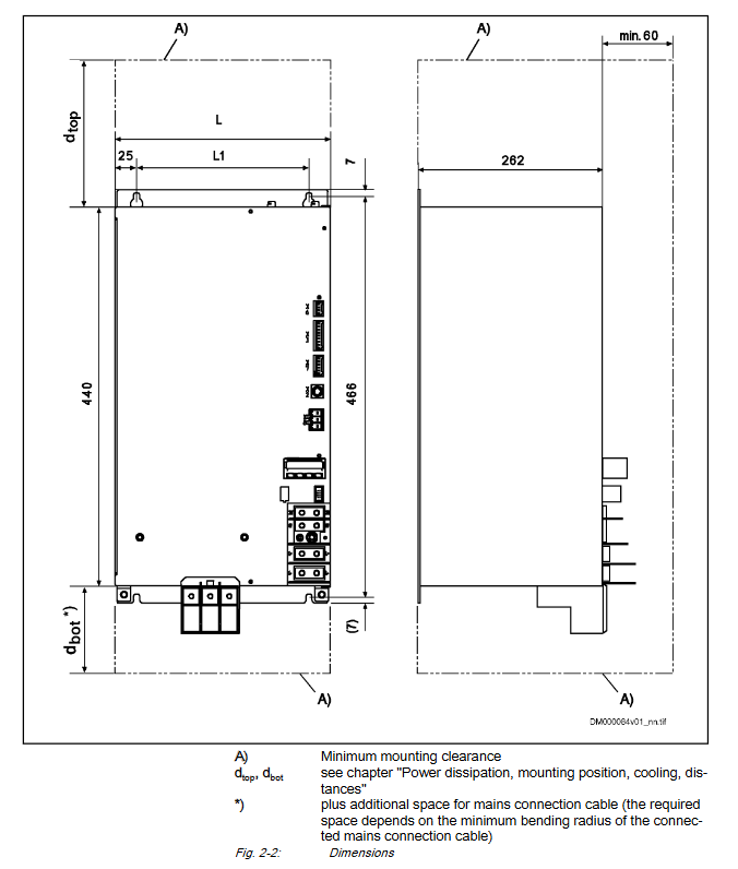
Physical universal dimensions: height 440mm, depth 262mm; minimum installation spacing at the top 300mm, bottom 130mm, horizontal spacing 0mm.
Key points of safety regulations
(1) Electrical safety
High voltage protection: The equipment has a dangerous voltage greater than 50V. After power failure, it is necessary to wait for 30 minutes for the capacitor to discharge and measure to confirm that there is no voltage before operation.
Grounding requirements: The grounding conductor must be permanently and reliably connected, with a leakage current greater than 3.5mA, and the minimum cross-sectional area must comply with the following table:
External conductor cross-sectional area (mm ²) Minimum cross-sectional area of a single grounding conductor (mm ²) Minimum cross-sectional area of two grounding conductors (mm ²)
1.5 10 2×1.5
2.5 – 2×2.5
4 – 2×4
6 – 2×6
10 10 –
16 16 –
25 25 –
Wiring safety: Do not plug or unplug connectors or touch electrical contacts when powered on; UL certified J-grade 600V AC fuses are required for branch protection.
(2) Battery safety
Heating, dismantling, charging, or using open flames are prohibited as they may cause explosions, leaks, or burns.
When replacing the battery, use the designated model to avoid damaging the electrical components of the equipment; Waste batteries need to be recycled separately and comply with national environmental regulations.
(3) Operational safety
Only trained professionals are allowed to install, operate, and maintain the equipment, and they must be familiar with safety regulations and equipment functions.
Prohibit unauthorized modification of equipment structure or decompile software components; Only accessories and spare parts approved by Bosch Rexroth can be used.
The equipment needs to be installed in external enclosures such as control cabinets to prevent foreign object intrusion, water ingress, and direct contact.
Installation and wiring specifications
(1) Installation requirements
Installation method: Fixed on the installation surface of the control cabinet, with reserved heat dissipation space (top 300mm, bottom 130mm) to avoid blocking the air inlet and outlet.
Accessory adaptation: It can be paired with optional main power reactors (HNL) and power filters (HNF) to enhance electromagnetic compatibility.
Special model: HMV01.1R-W0120 requires an external fan unit HAB01 and must comply with the corresponding installation size requirements.
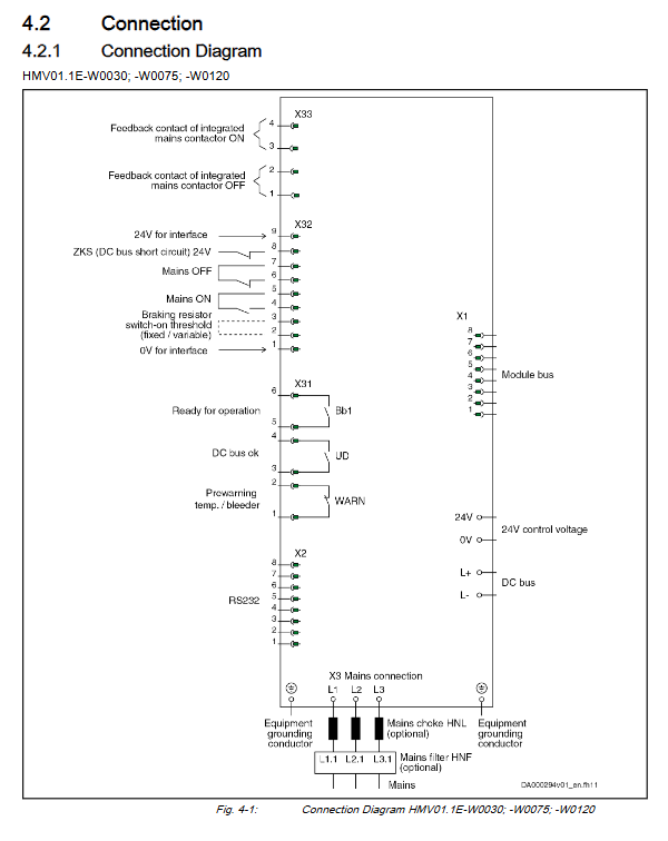
(2) Core interface and wiring
Key interface definition:
X3: Main power connection (L1/L2/L3), supporting a maximum wire cross-sectional area of 120mm ², with a tightening torque of 20Nm (M10 thread).
X2: RS232 interface, used for communication connection.
X31: Module bus interface; X32:24V interface power supply and signal input.
X33: Built in main contactor feedback contact (ON/OFF status); X40: External main contactor signal input.
Wiring process: First connect the grounding conductor, then connect the main power supply and control voltage, and finally connect the signal interface; Wiring must comply with NFPA 79 and UL 508A standards, using copper wire (PVC insulated, conductor temperature 90 ℃).
Leave a comment
Your email address will not be published. Required fields are marked *