Product basic information
Product positioning and applicable scenarios Siemens Climatix ™ The S400 STD HVAC Controller (POS646 series) is a programmable modular controller designed specifically for residential and light commercial buildings. Its core is used for HVAC system control, including heat pumps, boilers, hybrid systems, cascade systems, heat exchange units (HIUs), and district heating (DHC) scenarios, supporting flexible customization for OEM customers.
Core models and physical characteristics
Model Type Installation Method Weight Protection Level Minimum Order Quantity (MOQ) Inventory Number (SSN)
POS466.05/100 PCB type screw installation 275g IP00 20 units S55384-C660-F100
POS466.65/100 HSG type (with housing) DIN rail/screw installation 427g IP20, 20 units S55384-C666-F100
POS466.65/101 HSG type (with housing) DIN rail/screw installation 479g IP20 1 S55384-C666-F101
Note: The logistics center is located in Nuremberg, Germany (DCN), and ordering requires providing the model number (ASN), inventory number (SSN), and quantity.
Compliance and reliability
Compliance certification: Compliant with EN 60730-1 standard, with EU CE (A5W00713702A), UKCA (A5W00713706A), RCM (A5W00713708A) certification, and environmental compatibility documents can be found in A5W00709166A (RoHS compliance, material composition, etc.).
Reliability: MTBF (mean time between failures)>65 years (calculated based on SN29500 standard at 20 ℃ environment), meeting the long-term stable operation requirements.
Hardware configuration and interface
1. Power parameters
Main power supply (T02 terminal): AC 230V (+10%/-15%), 50/60Hz, requires external overcurrent protection (slow melting fuse ≤ 10A or B/C/D type circuit breaker).
Power consumption: Minimum power consumption (controller only) 4.5W ± 0.2W (25 ℃), maximum power consumption 130VA (full load including secondary power supply).
Secondary power supply (providing power to peripherals with maximum current limit):
Secondary power supply voltage range maximum current note
5V(T28) DC 5V±2.5% 40mA –
12V(T28/T42) DC 12V±2.5% T28:40mA; T42:50mA –
24V (T24/T44/T50) DC 24V ± 10% 522mA (shared) maximum 3.5mF capacitive load
24V (T70, for expansion module) DC 24V ± 10% 1080mA maximum 3.5mF capacitive load
2. Core interface resources
I/O interface (18 multifunctional channels): Supports analog signals (NTC 1k/10k, Pt1000, LG-Ni1000, 0-10V DC, 0/4-20mA DC), digital signals (AC 230V/DC 24V), pulse counting (≤ 150Hz), frequency input (≤ 500Hz), PWM input/output (500Hz-2.5kHz), as specified in the terminal table (e.g. T28/T30/T34 for input, T24 for output).
Communication interfaces (9 types):
Interface Type Terminal Core Parameters Typical Applications
OpenTherm T40 point-to-point, 1kbps, non isolated heat pump/gas boiler controller integration
LINbus T42 19.2kbps, Non isolated, up to 2 LINbus devices such as pumps/fans can be connected
RS485 (non isolated) T44 Modbus RTU/BACnet MS/TP, up to 15 server room units (such as POL824), BMS integration
RS485 (isolated) T46 Modbus RTU, up to 15 server heat pump outdoor units, BMS equipment integration
Ethernet IP T56/T58 10/100Mbps, Support BACnet IP/Modbus TCP/IP cloud connection (Climatix IC) and BMS integration
USB-C T54 USB 2.0 OTG, USB-A to C adapter is required to connect WLAN stick (debugging) and USB storage (file transfer)
Expansion Interface (T70): Peripheral bus, supporting the connection of Climatix I/O expansion modules (such as POL966, POL95E) and communication expansion modules (such as POL935 OpenTherm, POL937 M-Bus), up to 3 I/O expansion modules+10 communication expansion modules (POL935).
3. LED status indication (BSP LED)
LED color/flashing mode status description
Red/Green Alternating (1Hz) Software Update Mode (Download Applications/Firmware)
The green constant light application has been loaded and is running normally
The yellow constant light application has been loaded but not running
Yellow flashing (50ms on/1000ms off) Application not loaded
Red flashing (2Hz) firmware error
Hardware malfunction with constant red light
Software and tool support
programming tools
Climatix Project Studio Automation/APRO: Used for HVAC application programming, providing Level 3 support:
Level 1: OEM independent programming (including heating, ventilation, and cooling application libraries and templates);
Level 2: APC (Application Programming Center) or local partners provide programming services;
Level 3: Siemens pre developed configurable applications (such as fresh air heat recovery HRV, district heating HCS/DHC).
Configuration and Debugging Tools
Climatix SCOPE: OEM used for HVAC unit configuration, with the ability to modify watch pages, text, language, access permissions, and trend records.
Climatix SCOPE Light: Simplified version for OEM laboratory testing.
Climatix smartHMI APP/API: Install and debug tools, connect controllers through mobile devices, and support commissioning.
Climatix DEVICE REST API: Factory integration interface used to access controller data.
Cloud Services and Remote Access
Climatix IC Cloud: Provides remote access and cloud services (such as data monitoring and remote control), with cloud service model POL0L2.01/STD (SSN: P55693-L121-A100), and communicates via Ethernet IP.
Selection and Accessories
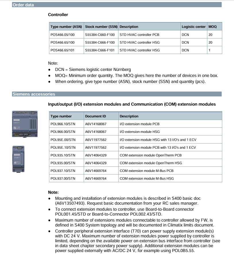
1. Selection of Expansion Modules
Module Type Model Description Document ID
I/O expansion module POL966.10/STN PCB type, expansion I/O A6V14168067
I/O expansion module POL966.00/STN HSG type, expanding I/O A6V14168067
I/O expansion module (with ECV) POL95E.00/STN HSG type, 13 I/O+1 ECV A6V11977562
Communication Extension (OpenTherm) POL935.10/STN PCB Type, OpenTherm Communication A6V14064329
Communication Expansion (M-Bus) POL937.00/STN HSG Type, M-Bus Communication A6V14669764
Note: The expansion module needs to be connected to a Board to Board connector (POL001.45/STD) or a Board to Connector (POL002.43/STD). If the power supply to the controller is insufficient, an external 24V power supply (such as POL0B5.55/STD, 75W) is required.
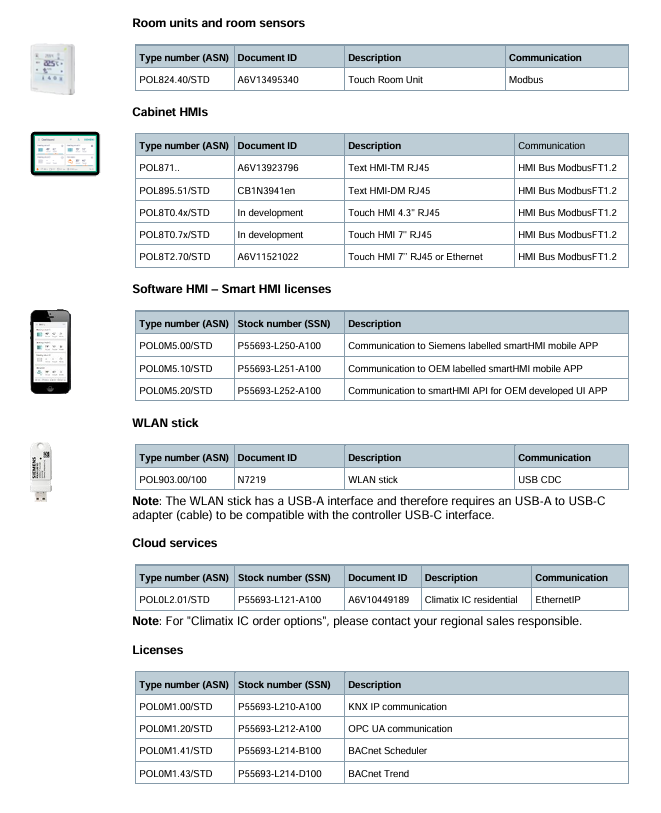
2. Key attachments
Room units and sensors:
Type, Model, Description, Communication Method
Touch room unit POL824.40/STD is used for user operation of Modbus
Outdoor temperature sensor QAC34 NTC 1k-
Immersion temperature sensor QAE16 PT100/1000-
HMI devices:
Type, Model, Description, Communication Method
Text HMI (TM) POL871. RJ45 interface HMI Bus Modbus FT1.2
Touch HMI (7 inches) POL8T2.70/STD RJ45/Ethernet HMI Bus Modbus FT1.2
Other attachments:
WLAN stick: POL903.00/100 (USB-A interface, requires conversion to C adapter, used for smartHMI connection);
External power supply: POL0B5.55/STD (24V DC/75W, supplying power to the expansion module);
Terminal connectors: Phoenix/Dinkle brand, such as POL001.45/STD (board to board), POL002.43/STD (board to wire), need to be ordered separately (MOQ 100 pieces).
Installation and safety regulations
Installation requirements
Space requirements: A gap should be reserved around the controller (Ethernet/USB-C end ≥ 30mm, I/O expansion module end ≥ 40mm);
Fixing method: fix with M3.5 metal screws (head diameter ≤ 8mm, not included in the supply);
Cable requirements: Different interface cables have a maximum length limit (such as Ethernet ≤ 100m, RS485 ≤ 1000m, LINbus ≤ 3m), and shielding is required for cables exceeding 3m.
Safety Warning
No internal fuses: All AC 230V circuits require external overcurrent protection (≤ 10A), with a total current not exceeding 10A;
Anti electric shock: AC 230V and SELV (Safety Extra Low Voltage) cables need to be double insulated, and the power supply should be disconnected before plugging or unplugging the terminals;
Anti static: When touching the PCB board, wear an anti-static wristband and and clothing to avoid direct contact with the components.
Maintenance and Disposal
Maintenance: The controller is designed to be maintenance free and does not require regular maintenance;
Disposal: Products and packaging cannot be used as household waste and must be classified and recycled according to local regulations. All personal data must be deleted before recycling.
Leave a comment
Your email address will not be published. Required fields are marked *