Basic Information
Applicable oscilloscopes: specifically designed for Tektronix TDS3000 series (such as TDS3054, TDS3012) and TDS500 series digital oscilloscopes;
Core positioning: Compact high impedance passive probe, suitable for voltage signal measurement, especially suitable for probe accessories with a size of 3.5mm;
Safety operation standards (ensuring the safety of personnel and equipment)
1. Core security principles
Prohibited live operation: Do not plug or unplug the probe/test line when connected to a voltage source to avoid electric shock or equipment damage;
Terminal rating: The voltage/current rating of each terminal of the probe must be followed (such as the maximum input voltage CAT II 300V RMS), and cannot exceed; The common terminal is at ground potential and is prohibited from connecting high voltage;
Personnel qualifications: Only qualified technicians can perform maintenance procedures, and ordinary users are prohibited from disassembling probes;
Environmental restrictions: Do not use in damp, condensing, or explosive environments; Do not operate in environments with conductive pollutants (pollution level 2).
2. Safety terms and symbols
Application scenarios of terminology/symbol meanings
Warning signs may cause personal injury or death. “Touching the metal part of the probe may result in electric shock
CAUTION labeling may result in equipment/property damage, as “cleaning with benzene solvents may damage the casing”
DANGER identification of immediately accessible injury risks (such as high voltage) probe high voltage terminal labeling
Grounding symbol protection grounding terminal probe grounding terminal identification
Refer to Manual for detailed information on probe body labeling
3. Cleaning and maintaining safety
Cleaning method: Only use a soft cloth dipped in “mild cleaner+water” or “isopropanol” to wipe the probe housing and remove dirt;
Prohibited solvents: Benzene, toluene, xylene, acetone and other solvents should not be used to avoid corrosion of the shell;
Component protection: Avoid liquid infiltration into the probe during cleaning to prevent circuit short circuits.
Product features and operating points
1. Core product features
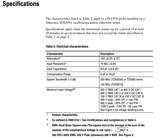
Characteristic Description Application Value
Attenuation ratio of 10X (± 0.5% DC) expands the measurement range of the oscilloscope and adapts to high voltage signals
The cable length of 1.3 meters provides sufficient measurement distance to reduce interference with the tested circuit
Input impedance 10M Ω (± 0.5%)+8.0pF (± 0.8pF) High impedance reduces signal load effect, low capacitance adapts to high-frequency signals
Accessory compatibility compatible with Tektronix 3.5mm probe accessories that can be paired with hooks, grounding leads, etc., to meet various measurement scenarios
2. Key operation: Probe compensation
Due to differences in input capacitance among different oscilloscopes, probe compensation must be performed when replacing the oscilloscope to avoid distortion of low-frequency signals. The compensation steps are as follows:
Connect the probe to the calibration signal output terminal on the front panel of the oscilloscope (usually a 1kHz square wave);
Press the “AutoSet” button on the oscilloscope, or manually adjust to make the screen display clear square waves (1ms/division mode);
Rotate the micro adjuster using the included adjustment tool (003-1433-02) through the probe “compensation box opening” until the screen displays a completely flat square wave (without overcompensation/undercompensation, as shown in Figure 1).
! [Probe compensation waveform] (schematic diagram of “Undercompensated/Overcompensated/Relatively compensated” in the document)
Undercompensated: The square wave front rises and then falls;
Overcompensated: the square wave front falls and then rises;
Proper compensated: The front edge of the square wave is vertical and the top is flat.
Detailed specification parameters
1. Electrical characteristics (core performance indicators)
Characteristic specification description remarks
The attenuation ratio is 10X ± 0.5% (under DC conditions) and the system characteristics require the use of an adaptive oscilloscope
Input resistance 10 M Ω± 0.5% high impedance design to reduce signal attenuation
Input capacitance of 8.0 pF ± 0.8 pF, low capacitance suitable for high-frequency signals, reducing phase distortion
Compensation range of 8 pF~18 pF covers the input capacitance range of most oscilloscopes
System bandwidth (-3dB) TDS3054:500 MHz; TDS3012:100 MHz strongly correlated with oscilloscope model
Maximum input voltage CAT I: 400V RMS/DC; CAT II:300V RMS/DC; CAT III: The peak voltage of 150V RMS/DC needs to refer to the duty cycle (e.g. 590V peak when<50% DF)
2. Physical and environmental characteristics
Description of Characteristics and Specifications
Net weight (including accessories)<110 g (0.24 lb) Lightweight design for easy handheld measurement
Temperature range: -15 ℃~+65 ℃ (+5 ℉~+149 ℉); Non work: -62 ℃~+85 ℃ (-80 ℉~+185 ℉) Suitable for laboratory and industrial environments
Humidity 5 cycles (120 hours), 95%~97% relative humidity meets Tektronix standard 062-2847-00 Class 3
Altitude<2000 meters to avoid the impact of high altitude and low pressure on insulation performance
When the input impedance curve frequency is 1Hz~10 ⁸ Hz, the impedance and phase characteristics are stable. Figure 3 provides a typical impedance curve
3. Certification and Compliance
The probe complies with multiple international safety standards to ensure compliance for use in different regions
European standards: EN 61010-1/A2 (Safety of measuring equipment), EN 61010-2-031:1994 (Handheld probe components);
North American Standard: UL 3111-1 (First Edition) CSA C22.2 No. 1010.1-92、CSA C22.2 No. 1010.2.031-94;
Pollution level: Pollution Degree 2 (prohibited from use in environments with conductive pollutants);
Overvoltage category: Supports CAT I/CAT II/CAT III (classified according to voltage levels, such as CAT III applicable to distribution systems).
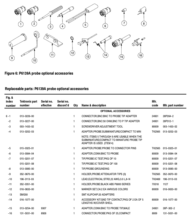
Accessories and Replacement Parts
1. Standard accessories (included with probe)
Accessory Name Tektronix Part Number Function Description
Scalable hook probe 013-0107-07 connects wires/component pins to achieve hands-free measurement
Compensation adjustment tool 003-1433-02 Adjust probe compensation adjuster
When using multiple probes with color marker tape 016-0633-00, the correspondence between the marker probe and the oscilloscope channel
SMT KlipChip and grounding lead 196-3305-00 connect the probe to a small/hard to reach grounding point
Low inductance grounding component 343-1003-01 (grounding ring)+195-4240-00 (short wire) reduces the inductance of the grounding lead and reduces high-frequency signal distortion
Insulated crocodile clip grounding lead 196-3113-02 probe grounding connection to grounding reference point
Probe protective shell 204-1049-00 protects the probe tip from mechanical damage
2. Optional accessories (extra optional)
Accessory Name, Part Number, Applicable Scenarios
BNC to probe tip adapter 013-0226-00 converts BNC interface signals into probe measurable tip signals
50 Ω BNC to probe adapter 013-0227-00 compatible with BNC signal source with 50 Ω impedance
Micro to small probe adapter 013-0202-03 enables compact probes to be compatible with small probe accessories
IC Test Probes (10 Pack) 015-0201-07 Accurate Measurement of IC Pins
Probe holder 352-0351-00 fixes the position of the probe and is suitable for long-term measurement
SMT KlipChip set (20 pieces) SMG50 batch SMT (surface mount technology) component grounding connection
3. Main replacement parts (for repair and replacement)
Component Name Part Number Remarks
Probe body (including cable) P6139A probe core component, replace as a whole in case of malfunction
Probe tip component (10X) 206-0441-00 contains 8.0pF capacitor and 9M Ω resistor. Replace when the tip is damaged
Grounding ring 343-1003-01 is the core component of the low inductance grounding component
Replace the BNC plug (male) 131-3219-00 when the BNC interface connecting the probe to the oscilloscope is damaged
Leave a comment
Your email address will not be published. Required fields are marked *