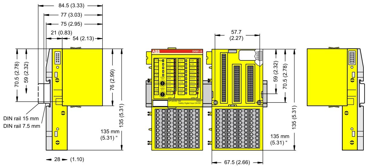
ABB DI581-S Safety digital input module
Size and weight
Dimensions: 67.5 x 76 x 62 mm.
Weight: Approximately 130 grams.
Technical Parameter
Power supply
The rated value of the process power supply voltage (UP) is 24 V DC, with an allowable fluctuation range of -15% to+20% and a maximum ripple of 5%.
Power reverse protection: equipped.
Rated protection fuse (fast): 10A.
Current consumed from UP during normal operation: 0.18 A; surge current of 0.1 A when starting a 30 V power supply (lasting for 2 seconds); Surge current of 0.06 A (lasting for 2 seconds) when starting the 24V power supply.
Installation and cooling
Installation position: Horizontal or vertical installation (the maximum working temperature drops to+40 ° C when installed vertically).
Cooling method: Natural convection, cable trays or other components inside the switchgear cabinet must not obstruct cooling.
Allowable values for power interruption (in accordance with EN 61131-2)
DC power interruption:<10 ms.
The time interval between two DC power interruptions (PS2):>1 second.
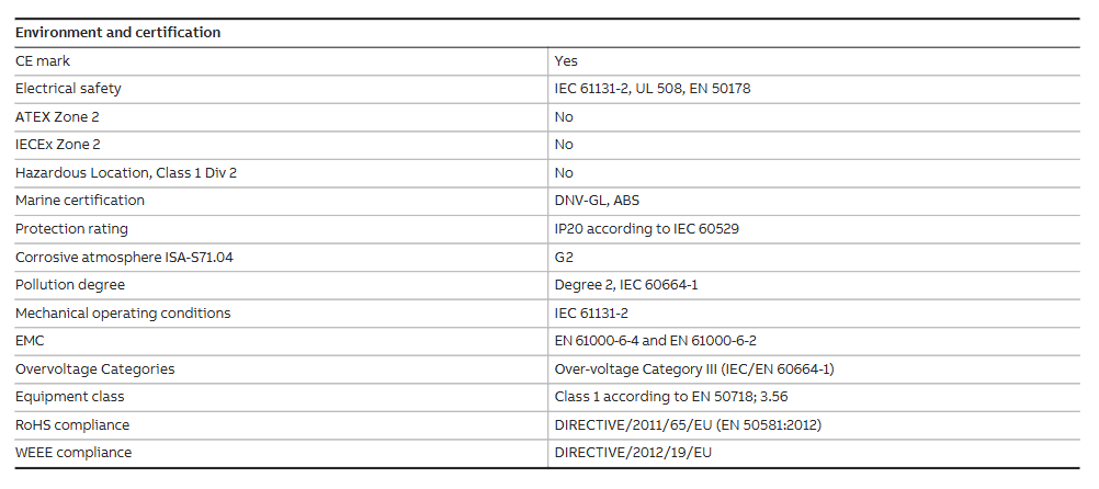
Environmental condition
Working temperature: 0 ..+60 ° C (DI581-S-XC supports a wider range in special versions).
Storage and transportation temperature: -40 degrees Celsius …+85 ° C.
Humidity without condensation: maximum 95%.
Working pressure:>800 hPa; Storage pressure:>660 hPa.
Working altitude:<2000 m; Storage altitude:<3500 m.
Mechanical properties
Protection level: IP 20.
The shell complies with UL 94 standard.
Vibration resistance (compliant with EN 61131-2, three-axis): 2 3.5 mm at 15 Hz; 1 g at 15… 150 Hz.
Impact test (three-axis): 11 ms half sine wave 15 g.
Mean Time Between Failures (MTBF): 102 years.
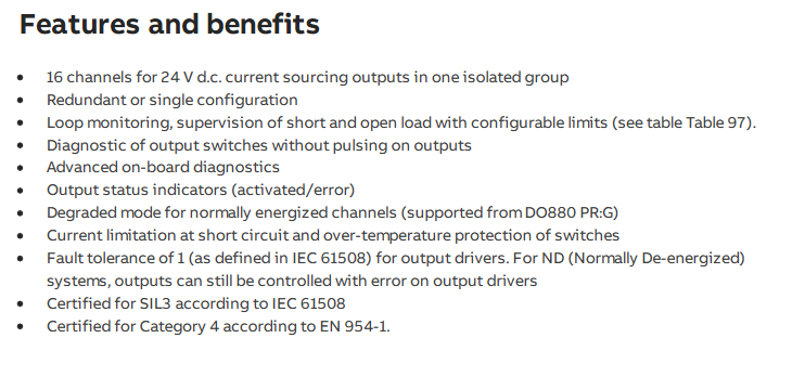
Technical parameters for secure digital input
Number of input channels per module: 16.
Installation and environmental precautions
Environmental adaptation
Ensure that the working environment of the module meets the parameter requirements: temperature (e.g. DI581-S conventional type is 0~+60 ° C, extreme type DI581-S-XC is -40~+70 ° C), humidity (maximum 95% non condensing), altitude (most modules<2000m), avoid corrosive gases, severe vibrations (in accordance with EN 61131-2 standard), and strong electromagnetic interference.
When installing some modules vertically (such as DI581-S), they need to be downgraded (with a maximum temperature of+40 ° C) to ensure that natural convection cooling is not hindered by cable trays or other components.
Mechanical Installation
Installed with 35mm DIN rails (7.5mm or 15mm depth), the tightening torque meets the requirements (such as DI581-S with 1.2 Nm) to avoid loosening and poor contact.
The module protection level is mostly IP20 and needs to be installed in a closed control cabinet to prevent direct contact with dust and liquids.
Precautions for Electrical Connections
Power Supply and Voltage
The power supply must comply with PELV/SELV specifications (such as DI581-S 24V DC power supply fluctuation range -15%~+20%, ripple ≤ 5%), avoid overvoltage (such as DI581-S can withstand up to 30V DC) or reverse connection (most modules have reverse connection protection, but caution is still needed).
When configuring redundant power supplies, ensure that the switching time between the two power supplies is less than 10ms (in accordance with EN 61131-2) to avoid module restarts or data loss.
Wiring specifications
Signal cables and power cables should be wired separately with a spacing of ≥ 10cm. The shielding layer should be grounded at one end to reduce electromagnetic interference (such as the RS-232/485 communication line of CI853, which needs to be shielded).
The terminal wiring of digital input/output modules (such as DI581-S) needs to distinguish between positive and negative signals (UP/ZP) to avoid short circuits (although the module has short circuit protection, it may affect other channels).
Configuration and operation precautions
Software configuration
Use official tools such as Control Builder and Automation Builder to configure and ensure firmware version is compatible with the module (e.g. AC500 CPU firmware updates need to be done through an SD card or tool to avoid firmware damage caused by power outages).
Redundancy configuration (such as module redundancy in CI853) requires enabling corresponding parameters, verifying the normal switching function before putting it into operation.
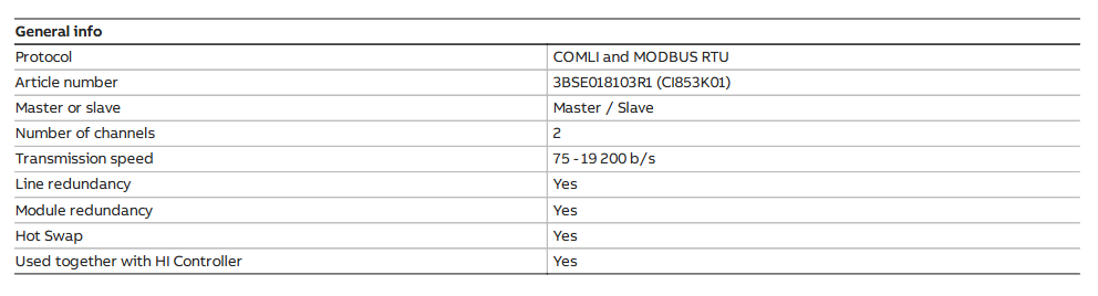
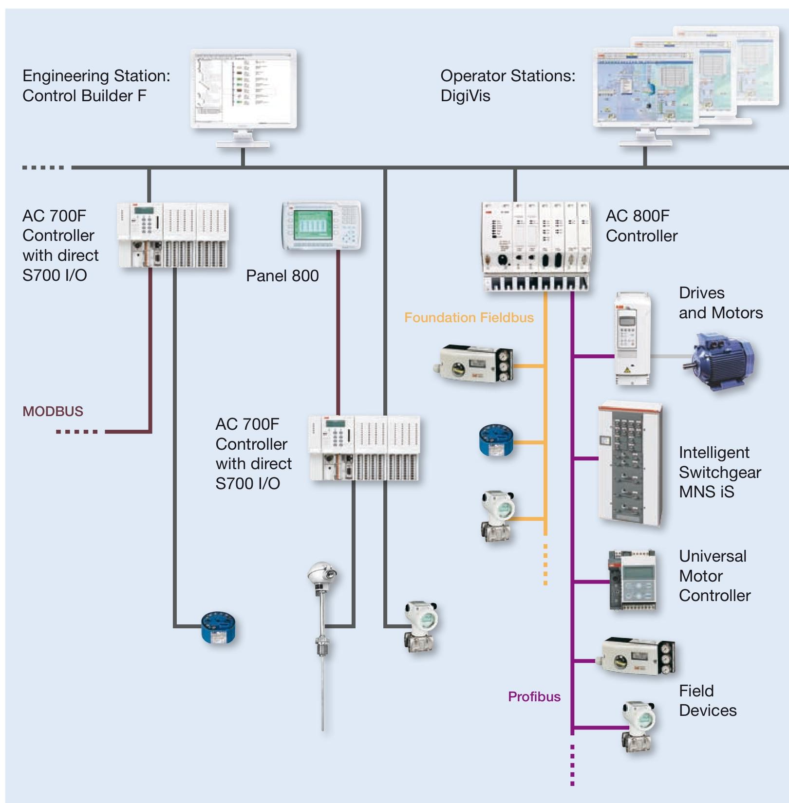
Protocol and Communication
The communication module (such as CI853 supporting MODBUS RTU, COMLI) needs to match the protocol parameters of the slave device (baud rate, parity check, etc.), and the DriveBus of CI858 needs to pay attention to the bus topology (multiple drives require NDBU branch units).
Hot plugging operations are only performed when the module is supported (such as CI853, CI858). Before plugging, ensure that there are no data transmission peaks to avoid communication interruptions.
Safety and maintenance precautions
Special requirements for security modules
The safety input module (such as DI581-S) needs to perform regular self checks (such as program flow control, RAM/CPU diagnostics) to ensure compliance with SIL certification requirements and prohibit bypassing safety function configurations.
Extreme environment modules (such as DI581-S-XC) need to be derated when the temperature is greater than 60 ° C (such as when the number of activated input channels is ≤ 50%) to avoid overheating damage.
Battery and data backup
CPU modules with batteries (such as AC500) need to be regularly checked for battery level (through function blocks or tools). When the battery level is ≤ 20%, they should be replaced in a timely manner. During replacement, the module should be powered to prevent loss of retention data.
Important data (such as the retain variable) is recommended to be backed up regularly through an SD card (using the pms_ram_deport function block for AC500 v3) to avoid data loss caused by battery failure.
Fault handling
When the module reports an error, priority should be given to checking the LED indicator lights (such as the channel LED of DI581-S and the fault LED of CI853), and troubleshooting wiring, power, or configuration issues should be carried out in conjunction with the manual. Blindly replacing the module is prohibited.
When modules involving safety circuits (such as DI581-S) fail, they need to be shut down according to safety procedures, and after troubleshooting, they can be reset using tools. Forced operation is prohibited.
Terminals for channels I0 to I7: 2.0 .. 2.7; Terminals for channels I8 to I15: 4.0 4.7.
All input reference potential terminals (negative pole of process power supply voltage, signal name ZP): 1.9… 4.9.
Electrical isolation from other parts of the module (I/O bus): available.
Input type (compliant with EN 61131-2): Type 1.
Input delay (0 ➔ 1 or 1 ➔ 0): configurable, 1 .. 500 ms。
Input signal indication: Each channel has a yellow LED, and when the input signal is high (signal 1), the LED lights up.
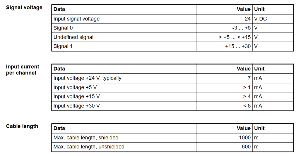
Signal voltage
Input signal voltage: 24 V DC.
Signal 0: -3 .. +5 V。
Undefined signal:>+5 .. < +15 V。
Signal 1:+15 .. +30 V。
Input current per channel
When the input voltage is+24 V: typical 7 mA.
When the input voltage is+5 V:>1 mA.
When the input voltage is+15 V:>4 mA.
When the input voltage is+30 V:<8 mA.
Installation and environmental precautions
Environmental adaptation
Ensure that the working environment of the module meets the parameter requirements: temperature (e.g. DI581-S conventional type is 0~+60 ° C, extreme type DI581-S-XC is -40~+70 ° C), humidity (maximum 95% non condensing), altitude (most modules<2000m), avoid corrosive gases, severe vibrations (in accordance with EN 61131-2 standard), and strong electromagnetic interference.
When installing some modules vertically (such as DI581-S), they need to be downgraded (with a maximum temperature of+40 ° C) to ensure that natural convection cooling is not hindered by cable trays or other components.
Mechanical Installation
Installed with 35mm DIN rails (7.5mm or 15mm depth), the tightening torque meets the requirements (such as DI581-S with 1.2 Nm) to avoid loosening and poor contact.
The module protection level is mostly IP20 and needs to be installed in a closed control cabinet to prevent direct contact with dust and liquids.
Precautions for Electrical Connections
Power Supply and Voltage
The power supply must comply with PELV/SELV specifications (such as DI581-S 24V DC power supply fluctuation range -15%~+20%, ripple ≤ 5%), avoid overvoltage (such as DI581-S can withstand up to 30V DC) or reverse connection (most modules have reverse connection protection, but caution is still needed).
When configuring redundant power supplies, ensure that the switching time between the two power supplies is less than 10ms (in accordance with EN 61131-2) to avoid module restarts or data loss.
Wiring specifications
Signal cables and power cables should be wired separately with a spacing of ≥ 10cm. The shielding layer should be grounded at one end to reduce electromagnetic interference (such as the RS-232/485 communication line of CI853, which needs to be shielded).
The terminal wiring of digital input/output modules (such as DI581-S) needs to distinguish between positive and negative signals (UP/ZP) to avoid short circuits (although the module has short circuit protection, it may affect other channels).
Configuration and operation precautions
Software configuration
Use official tools such as Control Builder and Automation Builder to configure and ensure firmware version is compatible with the module (e.g. AC500 CPU firmware updates need to be done through an SD card or tool to avoid firmware damage caused by power outages).
Redundancy configuration (such as module redundancy in CI853) requires enabling corresponding parameters, verifying the normal switching function before putting it into operation.
Protocol and Communication
The communication module (such as CI853 supporting MODBUS RTU, COMLI) needs to match the protocol parameters of the slave device (baud rate, parity check, etc.), and the DriveBus of CI858 needs to pay attention to the bus topology (multiple drives require NDBU branch units).
Hot plugging operations are only performed when the module is supported (such as CI853, CI858). Before plugging, ensure that there are no data transmission peaks to avoid communication interruptions.
Safety and maintenance precautions
Special requirements for security modules
The safety input module (such as DI581-S) needs to perform regular self checks (such as program flow control, RAM/CPU diagnostics) to ensure compliance with SIL certification requirements and prohibit bypassing safety function configurations.
Extreme environment modules (such as DI581-S-XC) need to be derated when the temperature is greater than 60 ° C (such as when the number of activated input channels is ≤ 50%) to avoid overheating damage.
Battery and data backup
CPU modules with batteries (such as AC500) need to be regularly checked for battery level (through function blocks or tools). When the battery level is ≤ 20%, they should be replaced in a timely manner. During replacement, the module should be powered to prevent loss of retention data.
Important data (such as the retain variable) is recommended to be backed up regularly through an SD card (using the pms_ram_deport function block for AC500 v3) to avoid data loss caused by battery failure.
Fault handling
When the module reports an error, priority should be given to checking the LED indicator lights (such as the channel LED of DI581-S and the fault LED of CI853), and troubleshooting wiring, power, or configuration issues should be carried out in conjunction with the manual. Blindly replacing the module is prohibited.
When modules involving safety circuits (such as DI581-S) fail, they need to be shut down according to safety procedures, and after troubleshooting, they can be reset using tools. Forced operation is prohibited.