ABB REF542plus multifunctional protection
Core functions and characteristics of the device
Protection function
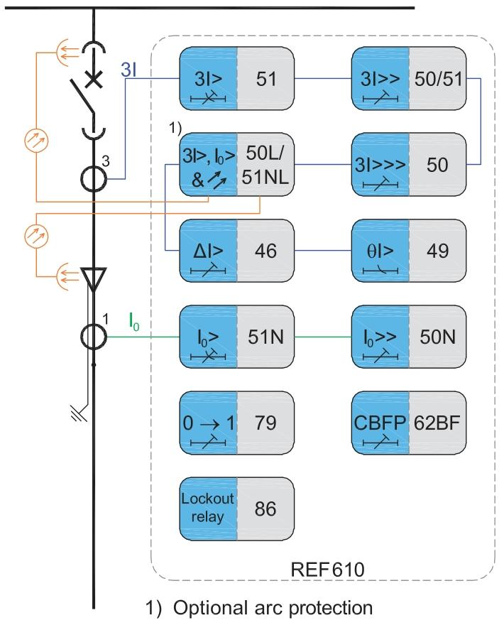
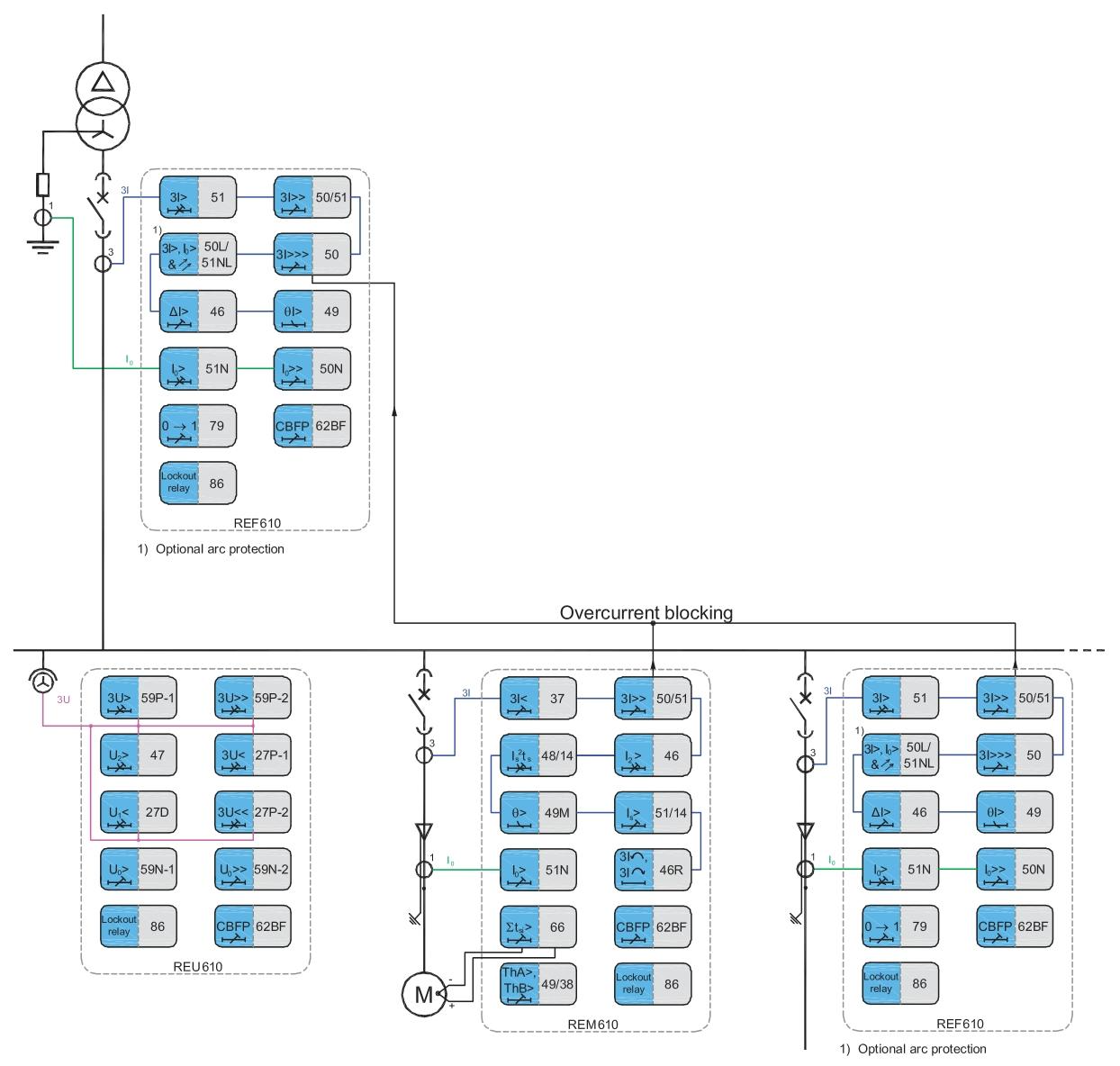
Core protection: covering overcurrent, ground fault, circuit breaker failure and other protections, supporting timed and inverse time characteristics, and can be configured with multiple sets of fixed value groups to adapt to different operating conditions.
Featured features:
Three stage overcurrent protection (including quick break, time limited quick break, and overload).
Non directional grounding fault protection, supporting high-sensitivity zero sequence current detection.
Statistics of circuit breaker operation frequency and life monitoring, assisting in preventive maintenance.
Control and operation
Control mode: Supports 4 control modes (local, remote, no control, local+remote), switched by electronic key to prevent misoperation.
One device operation: The “select execute” mechanism on the HMI panel can be used to control the opening and closing of the circuit breaker, in conjunction with interlocking logic to ensure operational safety.
Measurement and monitoring
Measurement quantity: Real time monitoring of three-phase current, voltage, power, frequency, electrical energy, etc., with accuracy in accordance with IEC standards and a refresh cycle of about 0.5 seconds.
Events and Wave Recording:
Record 30 latest protection events (including time, fault type, measurement value) without loss during power outage.
Support fault recording, storing 4 analog signals (current/voltage waveforms) and 8 digital signals (switch status) for easy fault analysis.
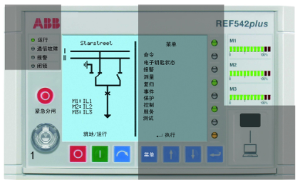
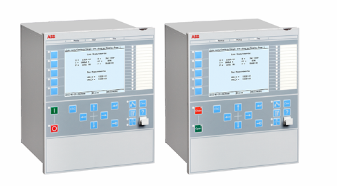
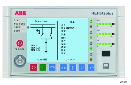
Human Machine Interface (HMI)
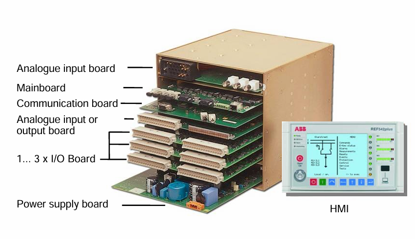
Hardware composition
Display area: 320 × 240 resolution LCD, with a single line diagram (SLD) of the device displayed on the left and menus and data displayed on the right. It supports switching between multiple languages such as Chinese and English.
Operating components: 8 navigation buttons (menu, up and down, enter, etc.), 3 sets of LED indicator lights (M1-M3, displaying load rate), 8 programmable three color LEDs (indicating protection actions, alarms, etc.).
Security component: Electronic key sensor, distinguishing between “protection key” (modifying protection parameters) and “control key” (switching control modes), supporting hierarchical management of permissions.
Menu Structure
Main menu: Contains submenus such as commands, alarms, measurements, events, protection, control, services, and testing, supporting operations such as parameter viewing and modification, event queries, and device self checks.
Featured feature page:
Debugging mode: requires a super user key to enter, which can directly drive switch output and monitor analog input for wiring verification.
Time synchronization: Supports local settings or remote synchronization of time through GPS and SCADA systems.
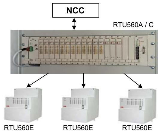
Communication and Configuration
Communication capability
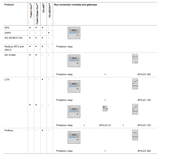
Supporting protocols: Modbus RTU, IEC 60870-5-103, SPA, LON, etc., standard RS485 interface, optional fiber optic communication module.
Data interaction: It can remotely upload/download configurations, read measurement values, record events and faults, and connect to a PC through infrared (IrDa) or RS232 interfaces.
Configuration management
Tool support: Configuration needs to be done through ABB’s dedicated operating tool (such as REF542comf), which supports offline configuration download and online configuration upload.
Parameter storage: Configuration and fixed values are stored in non-volatile memory, which is not lost when powered off. It supports two modes: temporary modification and permanent saving.
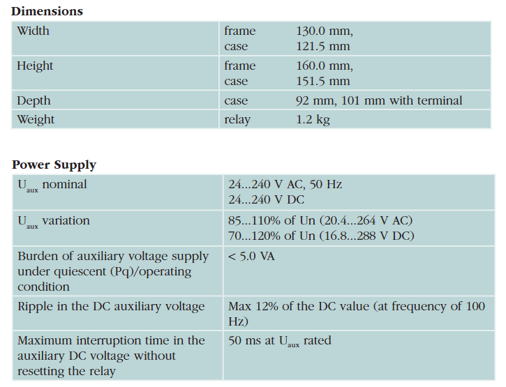
Installation preparation and environmental requirements
Environmental conditions
Temperature: Operating environment temperature -25 ℃~+55 ℃, storage temperature -40 ℃~+85 ℃, avoid drastic temperature changes.
Humidity: Relative humidity ≤ 93% (no condensation), avoid humid, dusty or corrosive gas environments.
Vibration and Shock: Compliant with IEC 60255-21 standard, vibration frequency 10-150Hz, acceleration ≤ 1g; shock acceleration ≤ 10g (11ms pulse).
Altitude: ≤ 2000m, if exceeded, it needs to be downgraded for use.
Installation space and safety
Space requirements: The device is approximately 177mm in width, 177mm in height, and 149mm in depth. At least 150mm of operating space should be reserved in front and behind for easy wiring and maintenance.
Safety regulations:
Only qualified personnel are allowed to install, strictly following local electrical safety regulations.
The device frame must be reliably grounded (grounding resistance ≤ 10 Ω) to avoid electrostatic damage to electronic components.
Cut off the auxiliary power supply before wiring to prevent electric shock.
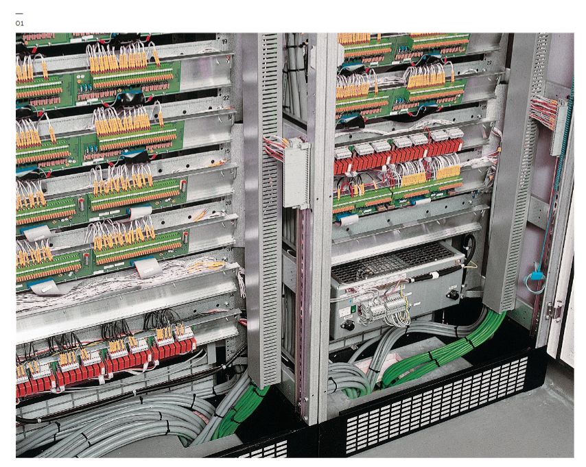
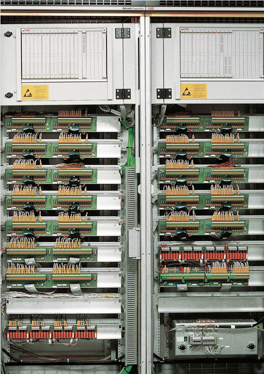
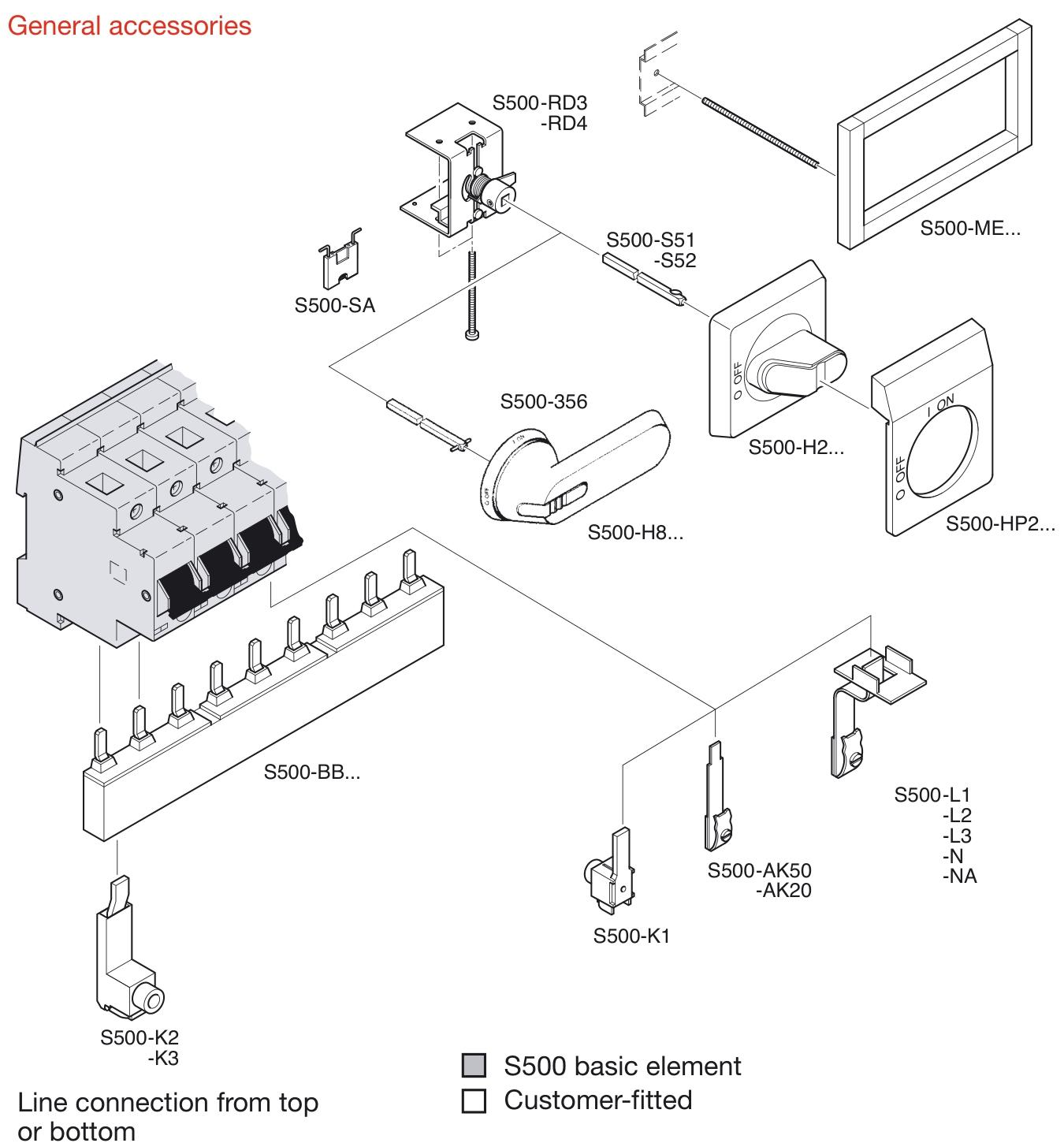
Hardware installation and wiring
Mechanical installation
Installation method: Supports panel embedded installation, 19 inch rack installation, or direct installation of circuit breaker cabinets, fixed with matching brackets to ensure stability and no looseness.
Installation steps:
According to the installation hole position fixing device, check the levelness (deviation ≤ 1 °).
Connect the grounding terminal to ensure reliable grounding.
Install the HMI panel, fasten it firmly, and avoid dust from entering through large gaps.

Wiring specifications
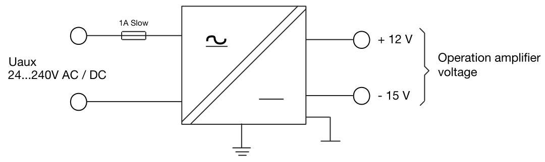
(1) Power wiring
The auxiliary power interface (X10) supports 24~250V AC/DC and needs to distinguish between positive and negative polarities. It is recommended to use 1.5mm ² single core copper wire.
The power circuit needs to be equipped with a 2A fuse to avoid overcurrent damage to the device.
(2) Analog input (X80~X88)
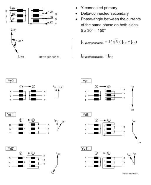
Current input: Supports CT (1A/5A) or Rogowski coils, three-phase current requires continuous wiring (such as L1 connected to X81, L2 connected to X82, etc.), and neutral wire connected to the common terminal.
Voltage input: Supports VT (100V) or resistive voltage divider, and the wiring of line voltage and phase voltage needs to be configured with corresponding devices (set through operating tools).
Wiring requirements: Analog cables need to be shielded, with the shielding layer grounded at one end and a distance of ≥ 100mm from the power cable to avoid electromagnetic interference.
(3) Switching input/output (X20~X41)
Switching input: 14 channels/module, supporting 24-250V DC, using optocoupler isolation, input current 2-20mA, distinguishing between “common terminal” and “signal terminal” during wiring.
Switching output: 8 channels/module, including relay output (capacity) 5A@250V AC/DC), Used to drive circuit breaker coils or alarm signals, the output contacts need to be connected in parallel with freewheeling diodes (when inductive loads are present).
(4) Communication wiring
RS485 interface (X60~X61): using shielded twisted pair, A and B wires are connected correspondingly, and the terminal needs to be connected to a 120 Ω matching resistor, with a maximum communication distance of 1200m.
Fiber optic interface (X62~X65): Glass fiber optic or plastic fiber optic, with a bending radius of ≥ 100mm, to avoid signal attenuation caused by excessive bending.