Call us 24/7uaedcs@163.com
Welcome to the official website of CNIACS Automation Technology Co., Ltd!
Call us 24/7uaedcs@163.com

TOSHIBA VF-S15 frequency converter

Basic information of the document

Scope of Application

The document specifically lists the applicable models (including multiple voltage levels) for the Toshiba VF-S15 series frequency converter, as shown in the table below. Models marked with suffixes such as “Y-A38” and “Y-A65” are not applicable.

Example of input voltage level frequency converter model

Single phase 200V-240V VFS52S-2002PL__/- W1/Y-A *, VFS52S-2004PL__/- W1/Y-A*

Three phase 200V-240V VFS15-2002PM_/- W1/Y-A *, VFS15-2004PM_/- W1/Y-A*

Three phase 380V-500V VFS15-4004PL_/- W1/Y-A *, VFS15-4007PL_/- W1/Y-A*

Three phase 525V-600V VFS15-6015P_/- W1/Y-A *, VFS15-6022P_/- W1/Y-A*

Safety warnings and personnel qualifications

1. Warning system

The document categorizes safety warnings into two types, specifying risk levels and response requirements:

Warning type meaning Typical scenarios

Warning operation errors may result in death or serious injury. Touching live cables, repairing without discharge, and short circuiting DC bus capacitors

Incorrect operation of the solution may result in minor injuries or equipment damage, voltage incompatibility, capacitor aging, and performance degradation

2. Core security taboos (Warning level)

Do not touch live cables (such as printed circuit boards) inside the frequency converter, and use insulated tools;

Before maintenance, it is necessary to follow the process of “power off → paste the prohibition closing label → lock the power-off switch → wait for 15 minutes to discharge → measure the DC bus voltage<42V”;

Do not short-circuit PA/+and PC/- terminals or DC bus capacitors;

Before powering on, all cover plates must be installed and closed.

3. Personnel qualification requirements

Only qualified personnel are allowed to operate (subject to the following conditions):

Having received safety training, able to identify and mitigate risks;

Familiar with this manual and product documentation, proficient in electrical/mechanical system knowledge;

Understand international/national electrical codes and accident prevention regulations.

Detailed explanation of core security functions

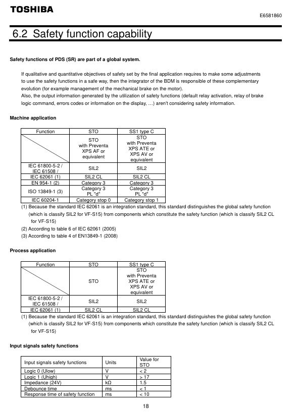
1. STO (Safe Torque Off)

Function definition: To put the motor into a torque free state (prohibiting motor start or free stop), cut off the energy supply to the motor, corresponding to IEC 60204-1 stop category 0 (uncontrolled stop).

**According to * *: IEC 61800-5-2 § 4.2.2.2, it should be noted that additional mechanical brakes are required for suspended load scenarios, and electronic components cannot replace anti electric shock isolation measures.

Security level:

Configuration method SIL (IEC 61508) PL (ISO 13849-1) EN 954-1 category

With/without Preventa module SIL 2 PL d 3

Key parameters: response time<10ms, logic input 0<2V, 1>17V, impedance 1.5k Ω.

Module requirements: Mechanical applications (compliant with IEC 60204-1) require mandatory use of Preventa modules (such as XPS AF) to prevent accidental restarts; Use as needed in other scenarios.

2. SS1 (Safe Stop 1, Safety Stop Class 1, Type C)

Function definition: First, slow down the motor according to the specified time delay. After the delay ends, trigger the STO function, corresponding to IEC 60204-1 stop category 1 (control stop).

Normative basis: IEC 61800-5-2 § 4.2.2.2, requires the use of specific safety relays to implement delay logic.

Security level:

Configuration method SIL (IEC 61508) PL (ISO 13849-1) EN 954-1 category

STO+Previnta module (such as XPS AV) SIL 2 PL d 3

Application logic: The deceleration delay time needs to be set according to the actual scenario, and the motor will enter a torque free state after the delay ends.

Compliance standards and safety performance

1. Follow the standards

Specific core requirements for standard categories

IEC 61800 series variable speed electric drive system safety requirements for drive systems

Functional Safety IEC 61508 Ed.2 Electrical/Electronic/Programmable Systems Functional Safety, Defining SIL Levels

Mechanical safety ISO 13849-1/2, EN 954-1 Safety components of mechanical control systems, defining PL levels and categories

Process Safety IEC 62061 Process Industry Safety Instrumented Systems, Distinguishing Global/Component SIL

2. Safety performance indicators

Taking the STO function as an example, the key performance parameters are shown in the following table:

Explanation of Indicator Values

SFF (Safety Failure Score) 96.7% represents the proportion of safety failures to total failures, reflecting the safety of the system

MTTFd (Mean Time to Failure) is the average interval between system failures in the year 16200

PFHequ_1y (annual hazard failure probability) 7.04 FIT 1FIT=10 ⁻⁹ times/hour, which means the annual failure probability is extremely low

HFT (Hardware Fault Tolerance) 1 allows one hardware fault to maintain safety functionality

Equipment type B complies with the definition of Class B subsystems in IEC 61508

System architecture and application limitations

1. Authentication architecture (3 types)

The document provides three certified security system architectures, adapted to different application scenarios:

Architecture Type Applicable Scenarios Core Configuration Compliance Standards

Case 1 Mechanical Applications – STO VF-S15+Preventa XPS AF Module EN 954-1, ISO 13849-1, IEC 60204-1

Case 2 Mechanical Applications – SS1 VF-S15+Preventa XPS AV Module EN 954-1, ISO 13849-1, IEC 60204-1

Case 3 Process Application – STO VF-S15 (without additional modules) IEC 61508 (SIL 2/SIL 1)

2. Application restrictions

Prohibited scenarios: Applications where the load may accelerate after shutdown (such as vertical conveyors, elevators, and winches) pose safety hazards;

Function priority: STO has the highest priority. If STO is triggered, no torque operation will be executed first regardless of whether other functions are activated or not;

Prerequisite: The motor/frequency converter needs to be matched with the application capacity, and the speed loop and torque characteristics should be correctly configured. If necessary, dynamic braking resistors and other options should be provided.

Maintenance and compliance documents

1. Maintenance requirements

Preventive maintenance: It is recommended to check the safety function once a year (such as opening the protective door to verify whether the frequency converter stops according to the set safety function);

Component replacement: After replacing non VF-S15 components such as motors and emergency stop switches, acceptance testing must be performed again;

Capacitor maintenance: For products stored for more than 2 years, the capacitor needs to be gradually boosted and activated through a variable power supply (25% → 50% → 75% → 100% rated voltage, each for 30 minutes) before use.

2. Compliance documents

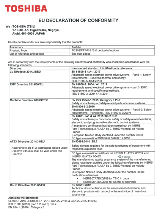
EU Declaration of Conformity: covering ATEX Directive, Machinery Directive, EMC Directive, to be executed in conjunction with the ATEX Guidelines and Safety Guidelines accompanying the product;

Declaration signing: Signed by both Technical Document Manager (Fredric Roussel, France) and Marketing Manager (Shin Okada, Japan), released in 2019;

Option compliance: Communication options (such as CANopen, PROFINET) and power options (such as EMC filters) require the use of original factory certified accessories (refer to the appendix options list).

Key issues

Question 1: Why is it necessary to use Preventa module for the STO function of VF-S15 frequency converter in mechanical applications? What is its core function?

Answer: Mechanical applications (compliant with IEC 60204-1 and the Machinery Directive) mandate the use of Preventa modules (such as XPS AF), with the following core reasons and functions:

Prevent accidental restart: If there is a power outage after the STO is activated, and the STO is mistakenly released during the power outage, the motor may automatically restart after the Preventa module is restored, posing a safety risk; The Preventa module can intercept this false trigger and ensure that manual operation is required to restart after power restoration, meeting the mechanical safety requirements of “reset does not trigger automatic start”;

Multi device emergency stop coordination: If the system contains multiple BDMs (background debugging modules), the Preventa module provides multiple safety output interfaces, which can achieve synchronous emergency stop control of multiple devices and meet the safety linkage requirements of complex mechanical systems;

Compliance guarantee: Only with the Preventa module can the STO function fully comply with the requirements of EN 954-1 category 3 and ISO 13849-1 PL d, ensuring that mechanical applications pass safety certification.

(Note: For non mechanical scenarios such as process applications, if there is no need to prevent accidental restarts or multi device collaboration, the Preventa module is not necessary.). )

Question 2: What is the core difference between the SS1 function (Safety Stop Class 1 Type C) of VF-S15 and the STO function? How to choose which function to use in practical applications?

Answer: The core differences and application selection logic between the two are as follows:

1、 Core difference

Comparison Dimension STO (Safe Torque Off) SS1 (Safe Stop Class 1, Type C)

The functional logic directly cuts off the motor torque, and the motor stops freely. First, it decelerates according to the set time, and then triggers STO after a delay

Stop category (IEC 60204-1) Category 0 (uncontrolled stop, fast but no deceleration) Category 1 (controlled stop, with deceleration process)

Applicable scenarios require emergency torque cut-off (such as personnel entering a dangerous area by mistake) and require smooth deceleration to avoid load impact (such as transporting fragile items)

Module dependent mechanical applications require Preventa modules, while other scenarios require the use of Preventa modules (such as XPS AV) to implement delay logic as needed

2、 Application selection principle

Select STO: When the scenario requires “immediately cutting off torque to avoid emergency risks” (such as operators accidentally touching dangerous areas or equipment operating abnormally), prioritize using STO to ensure that the motor quickly enters a torque free state;

Select SS1: When the scenario requires “smooth shutdown to protect the load or equipment” (such as conveying glass, precision parts, or avoiding mechanical impact during shutdown), use SS1 to achieve controlled shutdown through delayed deceleration and reduce the risk of load damage.

Question 3: According to the IEC 61508 standard, what does SIL 2 level mean for the STO function of VF-S15 frequency converters? How do its key performance indicators support the requirements of this level?

Answer: The meaning of SIL 2 level and the performance support of VF-S15 are as follows:

1、 The meaning of SIL 2 level (IEC 61508 Ed.2)

SIL (Safety Integrity Level) is an indicator that measures the ability of safety functions to resist dangerous failures. SIL 2 represents:

In high demand or continuous operation mode, the annual probability of failure (PFH) of safety functions must meet the requirement of 10 ⁻⁷ ≤ PFH<10 ⁻⁶;

Suitable for scenarios where dangerous events may cause serious injuries but have a low probability of occurrence, such as personnel protection for industrial machinery and overload protection for process equipment.

2、 Performance support for VF-S15 STO function

The STO function meets SIL 2 requirements through the following key indicators:

PFH index: The measured PFHequ_1y (annual equivalent hazard failure probability) is 7.04 FIT (1 FIT=10 ⁻⁹ times/hour), which is equivalent to an annual PFH of approximately 7.04 × 8760 × 10 ⁻⁹ ≈ 6.17 × 10 ⁻⁵? No, the document clearly states “PFHequ_1y=7.04 FIT”, combined with SFF=96.7% (high proportion of safety failures), the actual probability of dangerous failure is in the range of 10 ⁻⁷~10 ⁻⁶, which complies with SIL 2;

Hardware Fault Tolerance (HFT): HFT=1, which allows the STO function to still execute normally in the event of one hardware fault (such as a single input signal failure), meeting the hardware fault tolerance requirements of SIL 2;

Safety Failure Factor (SFF): SFF=96.7%, much higher than the minimum SFF requirement of IEC 61508 for SIL 2 (60%), indicating that most system failures are safety failures and the proportion of hazardous failures is extremely low;

Mean Time to Failure (MTTFd): MTTFd=16200 years, reflecting the extremely long interval of hazardous failures during long-term system operation, further verifying the stability of SIL 2.

image.png

TOSHIBA Color TV User Manual

Security Information (Core Warning)

Anti electric shock and maintenance: There are no user repairable parts inside the equipment, and it is forbidden to disassemble the shell (anti electric shock). Maintenance requires contacting professional personnel; The power plug shall be accessible at any time, and it shall be unplugged if it is not used for a long time or in extreme weather (rainstorm, lightning).

Environmental safety:

Stay away from splashing liquids and liquid containers (such as vases);

Avoid direct sunlight, open flames (such as candles), and high-temperature sources (electric heaters);

Reserve at least 5cm of ventilation space around the body and prohibit covering ventilation openings.

Physical security:

Use the original bracket and tighten the screws to prevent tipping. Do not place it on the ground or inclined surfaces;

Prevent child misoperation: Avoid children pressing/hitting the screen or inserting objects into device gaps; Plastic packaging bags should be kept away from infants and young children (to prevent suffocation).

Battery safety: The remote control uses 2 x AAA batteries, and it is prohibited to come into contact with high temperatures/open flames or mix dangerous/flammable materials; Prevent accidental ingestion by children (seek medical attention within 2 hours if ingested), stop using if the battery compartment is not tightly closed.

Special restrictions: The device is only suitable for altitudes below 2000 meters, dry environments, and temperate/tropical climates; Belongs to Class 1 laser equipment (normal use without risk).

Equipment identification and compliance certification

Explanation of the meaning of identification types and compliance requirements

Protective label 1. Class II equipment: No grounding required;

2. Class II equipment with functional grounding wire: The grounding wire is only used for functional purposes;

3. Grounding terminal: It needs to be connected to the building grounding wire-

Safety warning sign 1. Dangerous terminal: carries dangerous voltage during normal operation;

2. Battery identification: including user replaceable button batteries;

3. Laser Class 1 Identification: There is no risk of using the laser source-

Compliance certification 1. CE marking: compliant with EU directives (2011/65/EU, 2005/32/EC, etc.);

2. REACH compliance: Effective from June 1, 2007, restricted substances with a weight of>0.1% can be found on the official website;

3. EU waste label: Products/batteries need to be separately recycled (non household waste) Responsible party: Vestel UK (address: Langley, Berkshire SL3 6EZ)

Core functions and accessories

1. Core functions (some functions may not be available due to model differences)

Display and reception: Supports Ultra HD 4K (3840 × 2160) resolution (4x Full HD), DVB-T2 (Digital Terrestrial), DVB-C (Digital Cable), DVB-S2 (Digital Satellite) reception, optional Fransat installation.

Interfaces and Connections: HDMI interface (supports 4K signal), USB interface (2.0/3.0, 3.0 maximum current 1A), SCART interface, VGA (PC input), LAN (Ethernet) WLAN(802.11a/b/g/n)、 Bluetooth, headphone jack, SPDIF (fiber optic audio output).

Media and Control: USB playback (video/image/audio), EPG (electronic program guide), Teletext (graphic television), child lock, automatic shutdown (up to 8 hours), AVL (automatic volume limit), game mode (optional).

2. Standard accessories

Remote control (model CT-8053);

Battery: 2 x AAA;

Quick Start Guide;

Product Data Sheet;

Operation and Installation Guide

1. Basic operations

Operation Item Operation Steps Remarks

Remote control battery installation: 1. Open the back cover of the remote control;

2. Put in 2 AAA batteries (pay attention to the positive and negative poles);

3. When the battery runs out after covering the back cover, it should be replaced in a timely manner

Power connection 1. The device is suitable for 220-240V AC 50Hz;

2. After opening the box, it is necessary to adapt to room temperature before plugging it in;

3. Insert the plug into the power socket. The power cable should not be compressed or tangled, and wet cloth should not touch the plug

Power on/off: Press the standby button/number button/program button on the remote control, or the middle button on the body joystick;

Shutdown: Press the standby button on the remote control, or long press the middle button on the body joystick until power is still consumed during standby. To completely shut down, unplug the plug

2. First installation

Preparation: If Fransat installation is required, the Fransat card needs to be inserted into the CA interface first.

Step process:

Language selection: After booting up, select the language and press OK to confirm;

Signal source settings: Select digital antenna/digital wired/satellite/analog, satellite requires additional configuration (such as DiSEqC switch Single Cable);

PIN configuration: Some countries require setting a PIN (not 0000), and subsequent menu operations need to be verified;

Network settings: Select wired (Ethernet cable) or wireless (connect to WLAN, do not support hiding SSID);

Search for programs: The device automatically searches and saves programs, which can be sorted by LKN (logical channel number);

Child lock setting: optional parental control (age limit, program blocking) can be enabled;

Mode selection: Home mode (recommended) or Store mode (display function, some menus are not available).

3. USB media playback

Supported devices: 2.5-inch/3.5-inch hard drive (3.5-inch requires external power supply), USB flash drive, supports FAT32/NTFS format, hard drive above 1TB may fail formatting.

Supported formats (some key formats):

Media type supports formats/parameters

Video encoding: H.265( 4K@60fps , <100Mbps)、H.264( 4K@30fps )The MPEG1/2/4;

Containers: MP4, MKV, AVI, TS

Image JPEG (maximum 15360 × 8640), PNG (maximum 9600 × 6400), BMP (maximum 9600 × 6400)

Audio MP3 (8-320Kbps), AC3 (32-640Kps), FLAC (<1.6Mbps), AAC

Operation precautions: Do not unplug USB devices during playback/recording; The media browser only displays the first 1000 images.

System settings

1. Image settings (path: System>Bild Men ü)

Function Description of Settings Optional Parameters/Remarks

Image mode adjustment, picture quality style, cinema, gaming (optional), sports, dynamic, natural

Energy saving settings control energy consumption user-defined, minimum, medium, maximum, automatic, screen off, off; Only user-defined adjustable backlight

Noise reduction is effective when the signal noise is weak

Movie mode optimization: movie playback low/medium/high/off, supports split screen comparison (movie mode vs normal mode)

HDMI full range improvement, HDMI signal black level displayed only when HDMI input

2. Sound settings (path: System>Ton Men ü)

Core settings: volume, equalizer (adjustable only in user mode), balance (left and right channels), headphone volume (initially set low to prevent hearing loss);

Special Features:

AVL: Automatic volume limit to maintain consistent volume between programs;

DTS TruSurround: Turn on/off surround sound effects;

Dynamic bass (optional): enhances bass output;

Headphones/Lineout: When connecting an external amplifier, set it to Lineout, and when connecting headphones, set it to headphones (note that the headphone jack has the maximum output when Lineout).

3. Security and updates

Child lock (path: System>Einstellungen>Kindersicherung):

Menu lock: prohibits access to all menus/installation menus;

Age restriction: Block content based on program age rating (some countries default to 18+lock);

Internet lock: disable browser APP;

PIN management: Modify the PIN, default PIN is 0000 or 1234 (set non 0000 for the first time).

Software update (path: System>Einstellungen>Mehr>Softwareaktualisierung):

Manual update: Select “Search for updates”, find it, download and restart the installation;

Automatic update: Automatically search at 3:00 pm at night, download and install the next time it is turned on;

Attention: Do not unplug the power during the update process. If it fails, you can disconnect the power for 2 minutes and try again.

Troubleshooting and Technical Parameters

1. Common fault handling

Troubleshooting steps for fault phenomena

1. Check if the power cable is securely plugged in without turning on the device;

2. Press the power button on the device to try turning it on

Poor picture quality: 1. Confirm that the signal source selection is correct;

2. Check the antenna/cable connection (weak signal can easily cause distortion);

3. Confirm that the frequency is correct when manually setting

No sound 1. Check if it is muted (press the mute button on the remote control);

2. Increase the volume and check the sound balance settings;

3. Confirm the audio cable connection when connecting external devices

Remote control malfunction: 1. Replace 2 AAA batteries;

2. Confirm that the positive and negative terminals of the battery are installed correctly

2. Key technical parameters

PC input resolution (some commonly used):

Index resolution frequency

9 1024×768 60Hz

21 1366×768 60Hz

30 1920×1080 60Hz

HDMI signal support: up to 3840 × 2160 (4K) @ 60Hz, 4096 × 2160@60Hz High speed shielded HDMI cable (with ferrite core) is required;

USB current limit: USB 2.0 (body/side) maximum 500mA, USB 3.0 (optional, top left) maximum 1A, overcurrent may damage the device.

Environmental Protection and Waste Management

Product waste: Within the EU, it must be sent to a dedicated recycling point and cannot be mixed with household waste; Products produced after August 13, 2005 are marked with black horizontal stripes.

Battery disposal: Separate recycling, batteries containing Pb (lead), Hg (mercury), Cd (cadmium) should be labeled with corresponding chemical symbols to avoid environmental pollution.

TOSHIBA 2505AC, 3005AC, 3505AC mid to high end commercial

Core positioning and design philosophy of the product

core positioning

A high-performance color multifunctional multifunctional multifunctional multifunctional multifunctional machine specially designed for small and medium-sized workgroups. The three models only differ in output speed (25/30/35 pages/minute) and monthly load, while the other core functions and technical configurations remain consistent, which can meet the efficiency needs of teams of different sizes.

Design concept

With “CONNECT. IntegraTE. SIMPLIFY.” as the core, we solve complex document flow problems in office scenarios through compact body design, intelligent operation, and open platform integration. At the same time, we practice the concept of “green office” and balance performance and environmental protection needs.

Core functions and technological highlights

Core document processing capabilities

1. Copy function

Copy speed: The three models have 25/30/35 PPM (Letter size) to meet different efficiency requirements.

Copy resolution: 600 × 600 dpi, supports 25% -400% zoom ratio, and can make up to 999 consecutive copies.

Special features: Supports multi page merging, pagination, sorting, and can be combined with saddle/fold function to achieve saddle stitch binding and nail free folding, suitable for document production needs such as reports and manuals.

2. Printing function

Printing speed and resolution: At the same copying speed, it supports up to 1200 × 1200 dpi (PostScript 3) laser printing quality, and black and white printing can achieve 3600 × 1200 dpi (with smoothing processing).

Color technology: Adopting multi beam laser color technology, combined with Toshiba e-BRIDGE color configuration tool, customizable color configuration, matching Pantone color, spot color or other device output effects, 256 levels of grayscale ensure smooth transition of photos and illustrations.

Flexible printing support: Supports 12 × 47 inch banner printing, 11 × 17 inch color bleeding printing, compatible with AquaAce waterproof and tear resistant media; Equipped with the “print bypass” function, it can skip tasks that get stuck due to insufficient paper type/toner, avoiding printing bottlenecks.

Mobile and Network Printing: Supports AirPrint and Mopria protocols, and enables mobile printing on iOS and Android devices through the e-BRIDGE Print&Capture application; Compatible with Windows, Macintosh, Unix, Linux systems, supporting multiple network protocols such as TCP/IP, IPv4/IPv6, etc.

3. Scanning function

Scanning speed: Equipped with a 300 page capacity dual scan document feeder (DSDF), the double-sided scanning speed can reach 240 IPM, and the single-sided scanning speed can reach 120 IPM; Optional 100 page capacity reversing automatic document feeder (RADF) with double-sided scanning speed of 73 IPM.

Scanning Quality and Format: Supports resolutions of 100-600 dpi, with scanning modes including full-color, auto color, black and white, and grayscale; The output formats include TIFF, PDF, XPS, JPEG, etc. The embedded OCR function can generate searchable PDF and editable formats such as Word, Excel, PPT, etc.

Convenient transfer: Supports scanning to USB, network folders, email, and with Multi Station Print enabler, users can extract scanned files through authentication on any Toshiba MFP connected to the internet.

4. Fax function

Transmission performance: Compatible with Super G3 standard, with a modem speed of 33.6 Kbps, a single page transmission time of about 3 seconds, and a scanning speed of 0.7 seconds per page (up to 73 IPM).

Storage and group sending: Supports storage of 100 jobs (dependent on hard drives), can send to up to 2000 destinations in a group, and can receive up to 400 recipients per job. Data compression formats include MH/MR/MMR/JBIG.

Intelligence and convenient operation

Operation interface: Equipped with a 9-inch color WVGA tilt touch screen, supporting context sensitive help function, real-time access to manual instructions, and reducing the operating threshold.

Efficient homework management: supports unlimited homework appointments, and users can send task queues at any time; Equipped with a Paper Volume Indicators panel, it intuitively displays the paper type, size, and remaining quantity of each paper box; Service Module Design reduces maintenance time and costs.

Driver and integration: Provides a universal printing driver that supports PCL 6, PS3, XPS formats, and is paired with plugins such as Job Point and Job Replicator to achieve efficient operations such as multi device division of labor printing, multi form replacement, and batch printing separation.

Security protection system

Data storage security: Built in 320GB self encrypting hard drive (SED), compliant with FIPS 140-2 certification, supports automatic hard drive failure (ADI) and data overwrite functions to prevent data leakage.

Transmission and Access Security: Supports IPsec protocol encryption for data transmission between devices and networks, equipped with IP address filtering, MAC address filtering (10 groups each), SSL encryption, and other functions; Support IEEE 802.1X authentication and SMB packet signing to ensure network connection security.

User permission management: Supports account control for up to 10000 users or 1000 departments, and can restrict access to functions such as copying, printing, and scanning through device local authentication, Windows domain account, or LDAP server authentication; Equipped with mechanisms such as password policy, password expiration lock, and job access control.

Environmental Protection and Sustainability

Environmental certification: Obtained EPEAT Gold certification, Energy Star V2.0 certification, compliant with RoHS standards, and passed multiple international environmental certifications such as the Blue Angel logo (RAL UZ-171) and Nordic Swan.

Energy saving design: Supports 0.6W ultra-low power deep sleep mode to reduce standby energy consumption; Using recycled plastic materials to reduce environmental footprint.

Hardware configuration and specification parameters

Core hardware parameters

Category specific configuration

Intel Atom 1.33 GHz Dual Core Processor

4GB RAM

320GB FIPS 140-2 certified self encrypting hard drive

The standard paper capacity is 1200 pages, and it can be expanded to a maximum of 3200 pages (including accessories such as paper boxes and large capacity feeders)

Paper adaptation supports 3.9 x 5.8 inches to 12 x 18 inches paper, envelopes, 12 x 47 inches banners, weight range of 14-100 pounds cover paper (bypass feed)

Size and weight: 23 inches (width) x 25.2 inches (depth) x 31 inches (height), approximately 166 pounds

Power requirement 120V, 50/60Hz, 12A, maximum power consumption 1.5kW

Consumables and Durability

Toner capacity: Each CMY color toner can print 33600 pages, and black toner can print 38400 pages (based on 5% coverage and Letter size paper).

Monthly load: The maximum monthly load for color is 75K/90K/105K pages (corresponding to 2505AC/3005AC/3505AC), and the maximum load for black and white is 150K/180K/210K pages, meeting the high printing volume office needs.

Optional accessories and expansion capabilities

Document processing accessories

Paper feeding accessories: MR4000 dual scanning document feeder, MR3031 reverse automatic document feeder, KA5005PC paper table cover.

Paper Expansion: KD1058 Feed Base, KD1059LT 2000 Page Large Capacity Feeder, MY1048 Extra Drawer Module, MY1049 Envelope Paper Box (can hold 60 envelopes).

Binding and output accessories

Binding equipment: MJ1042 50 page built-in stapler, MJ1109 50 page console stapler, MJ1110 50 page saddle stitch stapler, MJ5015 homework separator.

Punching module: MJ6011 (compatible with MJ1042), MJ6105 (compatible with MJ1109/MJ1110) punching unit.

Connection and security accessories

Connectivity accessories: GN4020 wireless LAN/Bluetooth module, GR9000 Bluetooth keyboard, GR1250 accessory tray, GR1260 ten key numeric keypad.

Security accessories: GR1290 card reader bracket, GP1080 IPsec security enabler, GS1080/GS1085 embedded OCR enabler (single authorization/five authorization).

Software and Solution Expansion

Built in embedded web browser, supporting third-party solution integration;

Optional SharePoint connector, Exchange connector, and Google Docs connector can be used to directly upload documents to the cloud;

Support e-BRIDGE Fleet Management Software (EFMS 6.2) for device fleet management, facilitating unified monitoring and maintenance of multiple devices.

Applicable scenarios and core values

Applicable scenarios

Full functional office for small and medium-sized enterprises: covering document copying, color printing, contract scanning, and report fax needs for administrative, financial, marketing, and other departments.

Professional document production: supports banner printing, bleeding printing, saddle stitch binding, and adapts to the production of professional documents such as brochures, product manuals, conference materials, etc.

Multi team collaborative office: Cross device job retrieval is achieved through Multi Station Print enabler, embedded OCR simplifies document editing and retrieval, and improves team collaboration efficiency.

High security scenario: Industries such as finance and law can ensure the security of sensitive document processing through encryption of hard drives, permission control, data overwriting, and other functions.

core value

Efficiency improvement: features such as high-speed document processing, dual scan paper feeders, and unlimited job scheduling greatly reduce document waiting time;

Cost optimization: Large capacity consumables reduce single page printing costs, compact design saves office space, modular maintenance reduces service costs;

Safe and reliable: encryption and permission management that comply with international security standards to ensure the security of commercial data;

Flexible adaptation: Rich accessories and software extensions, customizable document processing flow according to business needs, adaptable to different industry workflows.

Certification and Compliance Information

Security certification: CC certification (ISO/IEC15408 EAL3+), IEEE2600.1 compliance (high security mode), WHQL certification (compatible with Windows series systems).

Environmental compliance: RoHS compliance, California Proposition 65 compliance, Canada ECP certification.

Other certifications: Novell, Citrix, SAP compatibility certification to ensure seamless integration with existing IT systems in the enterprise.

image.png

TOSHIBA External and Internal Hard Drives

External HDD: graded by location to meet different needs

External hard drives are divided into three levels: Premium, Advanced, and Standard. The core differences lie in material, functionality, and design, all of which support USB 3.0 (backward compatible with USB 2.0) and USB power supply.

1. Premium series: high-end design and comprehensive protection

Model Size Material/Design Core Function Capacity Warranty

Canvio Premium 2.5-inch aluminum casing with diamond cut edge automatic backup software (downloadable), password protection software (downloadable), Type-C adapter (A to C), soft bag 1TB/2TB/4TB for 3 years

Canvio for Desktop 3.5-inch piano high gloss finish, supports horizontal/vertical high-speed transmission, internal vibration sensor, ramp loading technology, safety lock slot 4TB/5TB/6TB-

2. Advanced Series: Balancing Performance and Design

Model Size Material/Design Core Function Capacity Warranty

Canvio Advance 2.5-inch high gloss piano paint automatic backup, password protection, high-speed USB 3.0 1TB/2TB/4TB-

Canvio Alu 2.5-inch integrated aluminum shell vibration sensor, ramp loading technology (anti-collision), USB power supply 500GB/1TB/2TB-

3. Standard series: High cost-effective basic model

Model Size Material/Design Core Function Capacity Warranty

Canvio Basics 2.5-inch matte black shell plug and play, USB 3.0 high-speed transfer 500GB/1TB/2TB/4TB-

Canvio Ready 2.5-inch dot pattern shell drag and drop operation, lightweight design 500GB/1TB/2TB/4TB-

4. Technical Parameters Table of External Hard Disk (Core Models)

Series model capacity interface shell backup software password lock additional function

Canvio Premium HDTW240ES3CA 4TB USB 3.0/2.0 Aluminum √√ Type-C Adapter, Soft Bag

Canvio for Desktop HDWC360EK3JB 6TB USB 3.0/2.0 Piano Paint √√ Safety Lock Slot

Canvio Advance HDTC940ER3CA 4TB USB 3.0/2.0 Piano Paint √√-

Canvio Alu HDTH320ER3AB 2TB USB 3.0/2.0 Aluminum √√ Vibration Sensor

Canvio Basics HDTB440EK3CA 4TB USB 3.0/2.0 Matte – Plug and Play

Canvio Ready HDTP240EK3CA 4TB USB 3.0/2.0 dot pattern – drag and drop operation

Internal HDD: Segmented by scenario to accurately match requirements

Internal hard drives are divided into 6 series according to application scenarios, all of which are SATA interfaces. The core differences lie in speed, cache, durability, and functional optimization, covering NAS, gaming, monitoring, video editing, and other scenarios.

1. Comparison Table of Core Series Parameters

Series Positioning Size Interface Speed Cache Capacity Range Key Features Warranty

N300 NAS dedicated 3.5-inch  SATA 6Gbit/s 7200rpm 128MB(4-8TB)/256MB(10-14TB)/512MB(16TB) 4TB-16TB 24/7  Running, high durability, compatible with RAID for 3 years

X300 Performance Class (Gaming/Design) 3.5 inches  SATA 6Gbit/s 7200rpm 128MB(4-8TB)/256MB(10-14TB)/512MB(16TB) 4TB-16TB  Dynamic caching technology, stable disk technology, high positional accuracy for 2 years

S300 monitoring dedicated 3.5-inch  SATA 6Gbit/s 5400rpm(4-5TB)/7200rpm(6-10TB) 128MB(4-5TB)/256MB(6-10TB) 4TB-10TB  Supports 64 cameras, 24/7 operation, shock resistant design for 3 years

V300 video streaming dedicated 3.5-inch SATA 6Gbit/s 5700rpm (500GB-2TB)/5940rpm (3TB) 64MB 500GB-3TB silent seek technology, temperature control, support for 16 cameras for 2 years

P300 desktop level (PC expansion) 3.5-inch SATA 6Gbit/s 7200rpm 64MB 500GB-3TB dual stage actuator, ramp loading design, vibration sensor 2 years

L200 notebook grade 2.5-inch  SATA 3/6Gbit/s 5400rpm 8MB(500GB-1TB 9.5mm)/128MB(1-2TB 7mm) 500GB-2TB  2 years of vertical magnetic recording (PMR) and tunneling magnetoresistance (TMR) technology

2. Detailed explanation of key series functions

N300 (NAS): Optimized for 24/7 uninterrupted operation, compatible with personal/small and medium-sized enterprise NAS systems, private cloud storage, supports RAID arrays, and ensures data reliability;

X300 (Performance): 512MB ultra large cache (16TB model) improves game loading and video rendering speed, suitable for high-end gaming PCs and graphics workstations;

S300 (Monitoring): Optimized for concurrent read and write operations of multiple cameras, supports high-resolution video recording to avoid frame loss, and is compatible with DVR/NVR systems;

L200 (notebook): 7mm ultra-thin design (1-2TB model) compatible with most notebooks, PMR technology improves storage density and meets the expansion needs of mobile devices.

Enterprise HDD: High reliability and large capacity, supporting enterprise applications

Enterprise grade hard drives are divided into AL series (high-performance) and MG series (large capacity), designed for mission critical scenarios such as servers and data centers, supporting 24/7 operation and high-intensity workloads.

1. AL series (high-performance enterprise level): suitable for high load applications

Model Capacity Interface Speed Cache Block Size Security Options Key Features

AL14SXB30EN 300GB SAS 12Gbit/s 15000rpm 128MB 512n SIE/SED low latency, persistent write cache, unlimited workload

AL15SEB24EP 2400GB SAS 12Gbit/s 10500rpm 128MB 4Kn SIE/SED adaptive storage array, virtual storage system

Core advantages: MTTF (Mean Time to Failure) reaches 2 million hours, supports SIE (Instant Erasure)/SED (Self Encryption), suitable for transaction oriented databases and high-performance computing (HPC);

Application scenarios: Tier 1 enterprise servers, big data analytics, virtualized storage.

2. MG series (large capacity enterprise level): compatible with massive storage

Model Capacity Interface Filling Gas Speed Cache Block Size Key Characteristics

MG08SCA16TE 16TB SAS 12Gbit/s helium 7200rpm 512MB 512e helium seal (reduces power consumption/noise), 550TB/year workload

MG08ACA16TA 16TB SATA 6Gbit/s helium 7200rpm 512MB 4Kn compatible with cloud storage and distributed file system

Core advantages: Some models adopt helium sealing technology (MG06 and above) to improve storage density and reduce operating power consumption; MTTF reaches 1.4-2.5 million hours and supports a 5-year warranty;

Application scenarios: Enterprise storage arrays, cloud/ultra large scale storage, data archiving and recovery.

3. Enterprise level hard drive reliability parameters

Series MTTF (hour) non recoverable error rate operating mode annual workload warranty

AL series 2 million 1/10 ¹⁶ 24/7 unlimited 5 years

MG series 1.4-2.5 million 1/10 ¹⁵ 24/7 550TB 5 years

Key issue

Question 1: In Toshiba’s internal hard drives, the N300 (NAS specific) and X300 (performance level) are both 3.5 inches and 7200rpm. What is the core difference? Which specific scenarios are suitable for each?

Answer:

The core difference between the two lies in the direction of functional optimization and adaptation to target scenarios, as follows:

Differences in functional optimization:

N300 (NAS specific): Core optimized for “24/7 reliability”, supports uninterrupted operation, adapts to RAID arrays, features high durability design (such as enhanced head stability, anti vibration optimization), cache capacity graded according to capacity (128MB for 4-8TB, 256MB for 10-14TB, 512MB for 16TB), with a focus on ensuring data integrity during concurrent access from multiple devices;

X300 (Performance Level): Core optimization of “high speed and responsiveness”, equipped with Toshiba Dynamic Cache Technology and Stable Platter Technology, 512MB ultra large cache (16TB model) to improve data read and write speed, improve positional accuracy, and reduce game loading and video rendering latency.

Applicable scenarios:

N300: Suitable for personal/small and medium-sized enterprise NAS systems, home multimedia servers, private cloud storage, small business file servers, and scenarios that require long-term stable operation and support simultaneous access by multiple users/devices;

X300: Suitable for high-end gaming PCs, graphics workstations, professional video editing computers, high-performance desktop all-in-one machines, and scenarios that require high speed and large cache to improve single machine high-performance computing and large capacity file processing efficiency.

Question 2: What are the advantages of “helium sealing” technology for Toshiba enterprise MG series hard drives? What are the differences in the applicable scenarios of SAS interface and SATA interface models in this series?

Answer:

1、 The core advantages of helium sealing technology

The MG06 and above models in the MG series adopt helium sealed design, which has three main advantages compared to traditional air filled hard drives:

Enhance storage density: The helium density is only 1/7 of that of air, and the internal resistance of the hard drive is smaller. It can stack more disks in the same 3.5-inch size, achieving higher capacity (such as MG08SCA16TE reaching 16TB);

Reduce power consumption and noise: Low resistance environment reduces motor operating load, reducing operating power consumption by about 20% (typical value decreases from 11.8W filled with air to 8.2W), while reducing noise caused by disk rotation and head movement, suitable for dense deployment in data centers;

Extended lifespan: Helium has stable chemical properties that can reduce internal component oxidation, and the sealed design isolates dust, improving the reliability of the hard drive. The MTTF (mean time between failures) reaches 2.5 million hours (some models), which is higher than the 1.4 million hours of air filled models.

2、 Scenario differences between SAS and SATA interface models

Interface type, core characteristics, applicable scenarios, representative models

SAS 12Gbit/s high bandwidth (12Gbit/s), support for multi device connections, hot swapping, strong fault tolerance enterprise level storage arrays, mission critical servers (such as transaction databases, virtualized storage), scenarios requiring high IOPS (input/output operations per second) MG08SCA16TE (16TB, helium, 512MB cache)

SATA 6Gbit/s has lower cost, strong compatibility, slightly lower power consumption, mainstream servers, ultra large scale cloud storage, data archiving/backup systems, and scenarios that require low IOPS but large capacity MG08ACA16TA (16TB, helium, 512MB cache)

Question 3: Which Toshiba internal hard drive should be selected for users who need to expand their laptop and configure a hard drive for their home monitoring system? What parameters should be focused on when choosing?

Answer:

1、 Laptop Expansion: Choose L200 Series

Recommended model: Choose according to capacity requirements – choose HDWL110EZSTA (7mm thickness, 128MB cache) for 1TB ultra-thin version; 2TB is required to select HDWL120EZSTA (9.5mm thickness, 128MB cache); Due to limited budget, choose the 500GB model HDWK105UZSVA (7mm thickness, 8MB cache).

Key focus parameters:

Thickness: Laptop hard drive slots support 7mm or 9.5mm, with 7mm models having wider compatibility (such as ultrabooks), while 9.5mm is only suitable for traditional laptops;

Interface: L200 supports SATA 6Gbit/s (mainstream) and SATA 3Gbit/s (compatible with old laptops), please confirm the laptop interface version (6Gbit/s is preferred unless otherwise specified);

Cache: 128MB cache (1-2TB 7mm model) is more suitable for multitasking (such as simultaneously opening documents and playing videos) than 8MB cache (500GB/1TB 9.5mm model), improving response speed.

2、 Home monitoring system: choose S300 series

Recommended model: Choose according to the number of cameras – select HDWT140UZSVA (4TB, 5400rpm, 128MB cache) for 4-8 cameras; Select HDWT360UZSVA (6TB, 7200rpm, 256MB cache) for cameras with 8-16 channels; Select HDWT31AUZSVA (10TB, 7200rpm, 256MB cache) for 16-64 high-resolution cameras.

Key focus parameters:

Speed and cache: 7200rpm (6-10TB model) is more suitable for concurrent recording of multiple cameras than 5400rpm (4-5TB model) to avoid frame loss; 256MB cache (6-10TB model) can reduce frequent head movement and improve continuous write stability;

Camera support: S300 supports up to 64 cameras (10TB model), depending on the number of home monitoring cameras (such as 4 cameras for the entrance, living room, and bedroom, 4TB is sufficient); If there are 12 roads including garage and balcony, 6TB or more is required;

Operation mode: It must support “24/7 operation”. The S300 has optimized the head life and heat dissipation design for monitoring scenarios to avoid long-term overheating faults.

TOSHIBA 1600XPi Series UPS Installation and Operation

Product Scope and Application

Product specifications: Single phase UPS, with a capacity coverage of 3.6/5.2/6/8/10/14/18/22 KVA, corresponding to output power (at 0.85 power factor) of 3.1/4.4/5.1/6.8/8.5/11.9/15.3/18.7 kW (22KVA is reduced to 18.7kVA at 50Hz)

Applicable scenarios: General electronic applications (computers, personal devices, office equipment, measuring equipment, industrial robots, household appliances, etc.)

Prohibited scenarios (DANGER): medical operating room equipment, life support equipment, fire-fighting equipment; Special scenarios (such as nuclear power plants, communication equipment, transportation equipment) require consultation with professional technical personnel (Warning)

Core Security Standards

Personnel qualification requirements

Only qualified personnel are allowed to install, operate, and maintain, and must meet the following requirements:

Read the complete manual to master the construction and operation of the equipment

Received safety training on circuit switching, grounding, locking and tagging (LOTO), etc

Master the usage of protective equipment (insulated gloves, safety helmets, etc.)

Having first aid skills and understanding of battery handling precautions

Safety symbols and signal words

Safety symbols: including safety warning (potential personal injury), prohibition (not operable), mandatory (must be executed), grounding (position of grounding conductor), electric shock (internal high voltage), explosion (components may explode), etc

Signal word grading:

DANGER: Immediate danger that may result in death/serious injury if not avoided (e.g. prohibited for use in life support equipment)

Warning: Potential danger, failure to avoid may result in death/serious injury (professional consultation is required for special situations)

CAUTION: Potential danger, may cause minor/moderate injury if not avoided (such as insulation tools required for battery operation)

NOTICE: Potential danger, may cause equipment/property damage if not avoided (if ventilation space is required for installation)

Key operation taboos

After power failure, wait for 5 minutes until the internal capacitor is completely discharged before opening the cover

Unauthorized modification of equipment (without written permission from Toshiba) is prohibited, otherwise all warranties will be invalidated and may result in UL/CHUL/CE/ETL certification being invalidated, causing personal injury or equipment damage

Batteries are prohibited from being baked or disassembled by fire (harmful electrolyte). Replacement must be carried out by authorized personnel from Toshiba, and the same type of battery pack must be used

Installation and wiring specifications

Installation environment requirements

Ventilation: Install in a well ventilated area, leaving at least 4 inches (10cm) of space around for ventilation and maintenance

Temperature: Operating temperature 0-40 ℃ (60Hz), 0-33 ℃ (50Hz); Storage temperature -20-40 ℃, optimal storage temperature 21 ℃

Other: Avoid moisture (30-90% humidity without condensation), dust/metal particles, direct sunlight, electrical noise sources, liquid intrusion, and place horizontally (without excessive vibration)

Input/output protection configuration

The user needs to configure a circuit breaker between the UPS input (mains) and output (load), with specifications as shown in the table below:

240VAC specification 3.6 kVA 5.2/6 kVA 8 kVA 10 kVA 14 kVA 18 kVA 22 kVA

Input circuit breaker 30 A 50 A 60 A 70 A 100 A 100 A 125 A

Output circuit breaker 20 A 35 A 45 A 60 A 80 A 100 A 125 A

Note: The above specifications are for equipment with 80% rated value

Terminal wiring and cable requirements

Terminal block type:

Type 1: Input at 208/240V, output at 120/208/240V, to be tripped according to the input voltage (208V short circuited to terminals 11-12, 240V short circuited to terminals 12-13)

Type 2: 240V input, 100/200V output, 100V output connected to 4-6 or 6-7 terminals, 200V output connected to 4-7 terminals

Cable specifications: All input, output, and grounding wires require 90 ℃ copper wire. The cable size and torque are shown in the following table:

Project Terminal Number Cable Size (AWG) -3.6kVA Cable Size (AWG) -5.2-6kVA Cable Size (AWG) -8kVA Cable Size (AWG) -10kVA Cable Size (AWG) -14-18kVA Cable Size (AWG) -22kVA Tightening Torque (lb. – in./N · m)

AC input line  1、2 10(8) 8(8) 8(1/0) 6(1/0) 4(1/0) 1(1/0) 14.2(1.56)

AC output line  4、5、7 12(8) 10(8) 8(1/0) 6(1/0) 4(1/0) 1(1/0) 14.2(1.56)

AC output neutral line  6 12(8) 10(8) 8(1/0) 6(1/0) 4(1/0) 1(1/0) 14.2(1.56)

ground wire  3、8 12(8) 10(8) 8(1/0) 6(1/0) 4(1/0) 1(1/0) 14.2(1.56)

EPO switch 14, 15 16 16 16 16 16 16 9.0 (0.99)

Remote switch 16, 17 16 16 16 16 16 16 9.0 (0.99)

Note: The maximum cable size that the terminal can accommodate is indicated in parentheses

Operation process and operating mode

Initial Startup (First Power Up)

Login: Log in with ADMIN privileges (default password ADMIN)

Parameter settings:

Enter the rated voltage (208V/230V/240V) and confirm with Write

Output rated voltage (208V/230V/240V), confirm with Write

Set date (format: Day mm/dd/yyyy, such as Mon 10/05/2009)

Set time (in 12 hour format, such as 12:15 PM)

Charging: After initial startup, the battery needs to be charged for at least 24 hours (with the input circuit breaker open), otherwise the backup time will be shortened

Normal start and stop

Start: Open the rear main circuit breaker (MCCB) of the UPS and confirm that the “On Line” green light on the front panel is on; If it’s not on, press the RUN button for 3 seconds (hear a beep sound)

Stop: Press the STOP button for 3 seconds (after a beep, the “On Line” light goes out and enters bypass mode); To completely stop, turn off the MCCB circuit breaker (all sensitive loads must be turned off first)

Core operating mode

Static Bypass mode: Automatically switches when UPS overload or internal failure occurs, with power directly supplied to the load through the bypass from the input, with a switching time of less than 1/4 cycle (no load interruption); After overload relief, it can automatically switch back (AutoXfer parameter needs to be enabled)

On Line mode: Normal operation mode, the input AC is converted to DC through a rectifier (including a boost chopper circuit), and the charging battery is simultaneously supplied to the inverter to generate high-quality sine wave AC output. The battery is always in a charging state

Battery Backup Mode: When the mains power is interrupted, the battery immediately supplies DC to the inverter and converts it to AC output; Backup time is 5-8 minutes (full load, depending on model), and the power supply will automatically stop when the battery voltage drops to the “shutdown voltage (Vmin)”

EPO mode (Emergency Power Off): remotely close the EPO switch (normally open), immediately cut off the UPS input circuit breaker, output, and battery circuit; After activation, wait for 5 minutes for discharge before maintenance

Battery management and maintenance

Key parameters of battery

Nominal voltage (Vnom): 3.6KVA is 144Vdc, 5.2-6KVA is 216Vdc, 8-22KVA is 288Vdc

Low voltage alarm (Vlow): 3.6KVA is 130Vdc, 5.2-6KVA is 192Vdc, 8-22KVA is 246Vdc

Shutdown voltage (Vmin): 3.6KVA is 114Vdc, 5.2-6KVA is 170Vdc, 8-22KVA is 227Vdc

Charging parameters: Charging is divided into three stages (constant current 1A → constant voltage → float charging), and it takes 24 hours to fully charge (12 hours for 90% charging)

Battery testing and storage

Test:

Automatic testing: Enable at startup, wait for the ‘Battery Test Frequency (CMD 655)’ time before re enabling after completion

Manual testing: In UPS online mode, log in with ADMIN privileges, set CMD 652=Disable, CMD 653=Enable, and CMD 655=0, and press the “BattTest” button on CMD 609; Test failed with ‘BTSTFL’ warning displayed

Storage:

Before storage: Start up and run without load for 24 hours to fully charge the battery, stop UPS and turn off MCCB

Storage conditions: Original packaging, wooden/metal tray, temperature -20-40 ℃, avoid humidity/dust/vibration

Maintenance: Charge every 9 months for temperatures below 20 ℃, every 6 months for temperatures between 20-30 ℃, and every 3 months for temperatures between 30-40 ℃

Preventive maintenance and component replacement

Daily maintenance: Keep the ventilation openings clean and regularly remove dust (using a vacuum cleaner for dusty environments)

Component replacement cycle:

Aluminum electrolytic capacitor: every 7 years

Fuse: Every 7 years

Cooling fan: Every 3.5 years for environments between 30-40 ℃, and every 5 years for environments below 30 ℃ (non hot swappable, needs to be replaced after disconnecting and discharging)

Battery: Depending on the ambient temperature, 20-25 ℃ is 5 years, 30 ℃ is 3.5 years, 35 ℃ is 2.5 years, 40 ℃ is 1.8 years, and 45 ℃ is 1.25 years (requiring overall replacement, using the same model of battery pack)

Fault Handling and Technical Appendix

Fault and warning codes

Fault code (partially critical):

BYPOH: Bypass overheating, check the fan/ambient temperature (>40 ℃ needs to be cooled down), if the issue is not resolved within 1 hour, the bypass will stop

CHRGOV: Charger overvoltage, UPS failure, record operating conditions and contact Toshiba service

DCOV: DC bus overvoltage, check input wiring/load (such as motor load), restart ineffective, contact service

Warning code (partially critical):

AOH: If the environment is overheated (internal temperature>50 ℃), check the air conditioning/fan. If it is overheated, turn off the device

BLFE: End of battery life (5-year cycle), contact Toshiba for replacement

LB: Low battery (<90% capacity), immediately turn off the load in an orderly manner and press the STOP button

Technical specifications (core parameters)

Input: Voltage 208/240V ± 10% to -30%, frequency 45-65Hz (automatic detection), power factor 0.98 (typical), THD<5% (linear load)

Output: Voltage regulation ± 3%, THD<3% (linear load)/<6% (nonlinear load), overload capacity 125%/30 seconds, 150%/10 seconds, bypass overload 125%/10 minutes, 1000%/1 cycle

Efficiency: AC-DC-AC efficiency ≥ 83% (3.6-10KVA),>86% (14-22KVA)

Size and communication interface

Size and weight (example):

Model size (H × W × D, in./mm) Unit weight (lb./kg) Shipping weight (lb./kg)

3.6KVA 22.1×10×34 / 561×254×864 260 / 118 308 / 140

22KVA 39.0×17.5×36.1 / 991×445×917 866 / 393 928 / 421

Communication interface:

Standard: Remote Contacts (DB9 male), RS-232C (DB9 female), RemotEye 4 network card (supports SNMP/HTTP)

Optional: EMD environmental monitoring equipment (monitoring temperature, humidity, dry contact signals)

TOSHIBA TOSBERT S11 series frequency converter

Document Overview and Basic Equipment Information

Document positioning: The official user manual for Toshiba TOSBERT S11 series frequency converters is designed for electrical engineers and maintenance personnel, covering the entire process of equipment installation, wiring, operation, parameter setting, fault handling, and maintenance, highlighting the characteristics of “compact” and “high compatibility”.

Equipment specifications and models:

Voltage level, power range, input type, applicable scenarios, typical models

200V level 0.1-1.5kW single-phase small equipment (laboratory instruments, household equipment) S11-2001S (0.1kW), S11-2015S (1.5kW)

200V level 2.2-15kW three-phase small and medium-sized motors (conveyors, packaging machines) S11-2002H (2.2kW), S11-2015H (15kW)

400V level 0.4-30kW three-phase medium and large equipment (fans, pumps, small machine tools) S11-4004H (0.4kW), S11-4030H (30kW)

Model coding rules: Taking “S11-4015H-C” as an example, the meanings of each part are:

S11: Series Code (TOSBERT S11 Series)

4: Voltage level (2=200V level, 4=400V level)

015: Capacity (15kW, 0.1kW model standard 001)

H: Basic configuration (H=standard, S=simple, L=low noise)

C: Optional functions (C=built-in communication module, F=built-in braking unit)

Core technical features:

Ultra compact design: The volume is reduced by 30% compared to the previous generation S7 series, and the size of the 0.4kW model is only 75 × 130 × 100mm, saving control cabinet space.

High protection and compatibility: basic model IP20, optional IP40 (anti solid foreign object+anti splash water); Compliant with NEMA ISO14001 Part 31, fully compatible with variable frequency drive, suitable for various asynchronous motors.

Control accuracy: In sensorless vector (SVC) mode, the output is 150% of the rated torque at 0.5Hz, with a speed accuracy of ± 0.1%, meeting the high-precision requirements of small and medium power.

Installation specifications and environmental requirements

1. Installation method (segmented by power)

Power Range Installation Method Installation Requirements Applicable Scenarios

≤ 0.4kW (200V single-phase/400V three-phase) DIN rail installation compatible with 35mm standard DIN rail, rail length ≥ inverter width, installation surface flatness ≤ 0.5mm Small control cabinet, distributed installation

≥ 0.75kW (200V three-phase/400V three-phase) vertical wall mounted installation fixed on a metal backplate with a thickness of ≥ 1.5mm, backplate grounded (≤ 10 Ω), screw torque 2.5-4.0N · m, medium-sized control cabinet, centralized installation

All models (IP40 configuration) require a larger ventilation gap (≥ 5cm on both sides) to be reserved for independent installation. It is prohibited to be in close proximity to heating equipment (such as contactors) in dusty/humid environments (such as food processing workshops)

2. Ventilation gaps and environmental restrictions

Ventilation gap (Figure 2-1):

Protection level: Top gap, bottom gap, left and right gap, back gap

IP20 ≥5cm ≥5cm ≥3cm ≥5cm

IP40 ≥8cm ≥8cm ≥5cm ≥8cm

Environmental restrictions:

Temperature: IP20 model -10 ℃~40 ℃, IP40 model -10 ℃~50 ℃; For every 1 ℃ increase in overheating, the rated power decreases by 1% (up to a maximum of 50 ℃).

Humidity: ≤ 90% RH, no condensation (condensation environment requires IP40+anti condensation heater).

Altitude: ≤ 1000m (over 1000m, power reduction of 1% per 100m, up to 3000m).

Vibration: Acceleration ≤ 0.5G (10-50Hz), amplitude ≤ 0.08mm (50-150Hz), exceeding the range requires adding or removing vibration pads.

3. Transportation and Storage

Transportation: Fill the packaging box with cushioning material, do not invert/flip it over, and avoid collision (to prevent damage to internal capacitors and modules).

Storage: Temperature -20 ℃~60 ℃, humidity ≤ 60% RH; long-term storage (≥ 6 months). Power on for 30 minutes every 6 months (no load) to activate the capacitor.

Wiring specifications and hardware configuration

1. Main circuit wiring (with differences in power segments)

(1) 200V level (single-phase/three-phase) main circuit terminal

Terminal identification function wiring requirements cable specifications (copper core)

L/N (single-phase), L1/L2/L3 (three-phase) power input series MCCB (capacity=1.2-1.5 × rated current), prohibit connecting compensating capacitors 0.1-0.75kW: 0.75mm ²; 1.5-15kW:1.5-4mm²

U/V/W motor output corresponds to motor U/V/W, reverse exchange any two phases; Cable length ≤ 30m (over 30m with output reactor) consistent with input cable

PE protective grounding Class 3 grounding (≤ 10 Ω), yellow green dual color wire, prohibited from sharing ≥ 1/2 of input cable with neutral wire, minimum 0.75mm ²

B1/B2 brake resistor connection ≤ 7.5kW can be connected to a built-in resistor; 7.5kW requires an external connection of ≥ 1.5mm ² (optional according to braking power)

(2) 400V level main circuit terminal

Power ≤ 7.5kW: The terminal configuration is the same as 200V three-phase, with the addition of “input filter terminal (F1/F2)” and optional EMC filter.

Power ≥ 11kW: divided into “main power input (L1/L2/L3)” and “reactor input (L1R/L2S/L3T)”, forced external input reactor (harmonic suppression, protection module).

2. Control circuit wiring

Analog input (AI1/AI2):

Terminal default function configurable function wiring requirements

AI1 0-10VDC (frequency command) 4-20mA (parameter P07.01) Load resistance ≤ 500 Ω, shielded twisted pair (0.5mm ²)

AI2 4-20mA (torque command) 0-10VDC (parameter P07.02) Same as AI1, cable length ≤ 20m

Switching input (DI1-DI6):

Default functions: DI1=forward rotation, DI2=reverse rotation, DI3=multi speed 1, DI4=multi speed 2, DI5=jog, DI6=reset.

Input method: leakage type (default)/source type optional (P06.01), 24Vdc ± 10%, current ≤ 8mA.

Communication interface:

Standard RS485 (terminals A/B), supports MODBUS-RTU, baud rate 9600-115200bps (P20.01).

Optional RS232 module (requires TX/RX/GND terminals) for direct communication with PC.

3. Wiring taboos

Do not connect compensation capacitors at the motor end (which may cause overvoltage tripping).

The distance between the control cable and the main circuit cable should be ≥ 15cm to avoid parallel wiring (reduce EMI interference).

After wiring the IP40 model, it is necessary to check whether the sealing ring is compacted to prevent dust/water vapor from entering.

Operation panel and core operations

1. Analysis of the operation panel

Panel layout (Figure 4-1):

Display: 2-line LCD screen (supports Chinese/English, parameter P00.02 switching), displaying frequency, current, and fault codes.

Buttons: RUN, STOP, MODE, △/▽ (parameter adjustment), ENTER (confirm).

Indicator lights: Power (PWR), Run (RUN), Fault (ALM).

Menu structure: First level menu (monitoring/parameters/faults) → Second level menu (parameter group P00-P29) → Third level menu (specific parameters).

2. Basic operation process (panel control)

Power on standby: Close the MCCB, the PWR light is on, the screen displays “0.0Hz”, and there is no ALM alarm.

Frequency setting: Press MODE to select “Panel Control”, press △/▽ to set the target frequency (such as 50Hz), and confirm with ENTER.

Start/Stop: Press RUN to start (RUN light on), press STOP to soft stop (deceleration time P03.02 defaults to 3 seconds).

Fault reset: When the ALM light is on, press STOP for 2 seconds to reset after troubleshooting.

3. External/Communication Control Operations

External control: P05.01=1 (external mode), DI1 is connected to the forward switch, AI1 is connected to the potentiometer, and the switch is closed to start.

Communication control: P05.01=2 (communication mode), PC sends instructions through MODBUS (such as writing frequency 0x0001=5000 → 50Hz).

Core functions and parameter configuration

1. Control mode and key parameters

Control mode parameters (P01.01) core parameters applicable scenarios

V/f control 0 P01.02 (V/f curve: 0=linear, 1=square) Fan/pump (variable torque)

Sensorless vector (SVC) 1 P01.04 (vector gain: 0.1-10.0), P04.01 (torque limit: 50-200%) machine tool/conveyor (constant torque)

2. Multi speed and brake control

16 speed operation: P08.01-P08.16 set the 16 speed frequency (0.0-400.0Hz), and select the combination of DI3-DI6 (such as DI3=ON → S1).

DC injection braking: P09.01=1 (enabled), P09.02=0-10Hz (starting frequency), P09.03=0-30% (voltage), suitable for positioning scenarios.

3. Energy saving function

Fan/pump energy-saving: P15.01=1 (enabled), P15.02=1 (square curve), energy-saving of 5-12%.

Automatic sleep: P15.05=1, P15.06=5.0Hz (sleep threshold), P15.07=10 seconds (delay), light load shutdown energy-saving.

Troubleshooting and Maintenance

1. Common fault codes and solutions

Fault code type, cause, and solution measures

OC1 acceleration overcurrent acceleration time short, motor short circuit, large load increase P03.01, motor insulation measurement, load reduction

OH1 module overheating fan fault, insufficient gap, environmental heat exchange fan (FS-6015), gap adjustment, cooling

OV1 bus overvoltage, high grid voltage, short deceleration, high regenerative energy measurement grid voltage, increased P03.02, connected to braking unit

GF grounding fault motor grounding, cable damage, grounding difference measurement motor insulation, cable replacement, rectification of grounding (≤ 10 Ω)

Err12 communication fault, cable breakage, baud rate mismatch. Check RS485 wiring and unify P20.01 parameters

2. Maintenance plan

Periodic project operation

Monthly visual inspection to ensure that the casing/terminals are free from damage or oxidation

Tighten the main circuit screws every 6 months with a torque of 2.5-4.0N · m

Clean the compressed air (0.2MPa) fan/heat sink every 6 months to dissipate heat

Measure the capacitance of the busbar every 2 years (attenuation ≤ 20%) through capacitance testing

Optional accessories and warranty

Optional accessories:

Accessory model and function

Input reactor ACL-S11-04 suppresses harmonics and increases power factor to 0.95

Braking resistor BR-S11-10 is compatible with 15kW models and can absorb regenerative energy

MOD-S11-RS232 communication module expands RS232 communication

External panel OP-S11-1M 1-meter cable, remote operation

Warranty terms:

Deadline: 12 months for the host and 3 months for the accessories.

Failure situation: unauthorized modification, overvoltage operation, natural disasters, etc.

Toshiba TOSBERT S7 series frequency converter

Document Overview and Basic Equipment Information

Document positioning: Toshiba TOSBERT S7 series frequency converter official user manual, covering the entire process of equipment installation, wiring, operation, parameter setting, fault handling, and maintenance, suitable for professional users such as electrical engineers and operation and maintenance personnel.

Equipment specifications and models:

Voltage level, power range, applicable scenarios, typical model examples

200V level 0.4-75kW small and medium-sized motor (conveyor, small pump) S7-2037H (200V/37kW)

400V class 0.75-630kW medium and large motors (fans, compressors, large pumps) S7-4220H (400V/220kW)

High voltage 6.6kV/11kV high-power equipment (high-voltage fan, large compressor) S7-HV630 (6.6kV/630kW)

Model coding rules: Taking “S7-4055H” as an example, the meanings of each part are as follows:

S7: Series Code (TOSBERT S7 Series)

4: Voltage level (2=200V level, 4=400V level, HV=high voltage level)

055: Capacity (55kW, direct rated power of high voltage level such as 630)

H: Configuration (H=standard configuration, F=with brake unit, C=with communication module)

Core technical features:

High control accuracy: In sensorless vector control (SVC) mode, 150% of the rated torque can be output at 0.5Hz, and in sensorless vector control (FVC) mode, the speed accuracy is ± 0.01%.

Multi mode compatibility: supports three control modes: V/f control, SVC, FVC, and adapts to different load types such as fans, pumps, and machine tools.

Flexible protection level: The basic model has an IP20 rating (finger touch only), and an optional IP40 rating (solid foreign object intrusion prevention) to meet different environmental requirements.

Strong anti-interference ability: The control circuit is equipped with a built-in filter and supports the selection of common mode inductors to reduce electromagnetic interference (EMI).

Installation and wiring specifications

1. Installation requirements

Installation method:

200V level (≤ 75kW), 400V level (≤ 75kW): Only supports vertical wall mounted installation and needs to be fixed on a metal bracket with a load-bearing capacity of ≥ twice the weight of the frequency converter.

400V level (≥ 90kW), high voltage level: floor mounted, requiring a dedicated base with a height of ≥ 10cm (to prevent water damage on the ground).

Environmental restrictions:

Temperature: -10 ℃~40 ℃ (up to 50 ℃ for models without casing), exceeding this range requires the installation of a cooling fan or air conditioner.

Humidity: ≤ 90% RH, no condensation (dehumidification device needs to be installed in condensation environment).

Altitude: ≤ 1000m (for every 100m increase, the rated output power decreases by 1%, up to a maximum of 3000m).

Vibration: Acceleration ≤ 0.6G (10-50Hz), amplitude ≤ 0.08mm (50-150Hz), exceeding it requires the installation of damping pads.

Ventilation gap (Figure 2-1):

Model power, top/bottom gap, left/right side gap, back gap

≤75kW ≥10cm ≥5cm ≥10cm

90-220kW ≥15cm ≥10cm ≥15cm

≥250kW ≥20cm ≥15cm ≥20cm

2. Wiring specifications

(1) Main circuit wiring (power segment differences)

200V level (0.4-75kW) and 400V level (0.75-37kW) (Figure 3-1):

Terminal name, function, wiring requirements

The R/L1, S/L2, and T/L3 three-phase power inputs require a circuit breaker (MCCB) with a capacity of 1.2-1.5 times the rated current of the frequency converter

U. The output of the V and W 3-phase motors corresponds to the U, V, and W terminals of the motor, and can be reversed to exchange any two phases

PE protection grounding Class 3 grounding, grounding resistance ≤ 10 Ω, wire diameter ≥ 1/2 of the main circuit power wire diameter

When the B1 and B2 braking units/resistors need to be connected for braking, an external braking unit can be connected. If the power is ≤ 15kW, an internal braking resistor can be connected

400V level (≥ 45kW) and high voltage level (Figure 3-2):

Add “input reactor terminals (L1R, L2S, L3T)” and force external input reactors (to suppress harmonics and protect power modules).

The brake terminals are divided into “B1, B2 (main brake)” and “B3, B4 (auxiliary brake)”, suitable for high-power braking requirements.

(2) Control circuit wiring

Analog inputs (AI1, AI2):

AI1: Default 0-10VDC (frequency command), can be switched to 4-20mA (load resistance ≤ 500 Ω) through parameter P07.01.

AI2: Default 4-20mA (torque command), switchable to 0-10VDC (parameter P07.02).

Switching input (DI1-DI8):

Default functions: DI1=forward rotation, DI2=reverse rotation, DI3=multi speed 1, DI4=multi speed 2, DI5=jog, DI6=reset, DI7=emergency stop, DI8=allowed operation.

Input method: leakage/source type optional (parameter P06.01), voltage 24Vdc ± 10%, current ≤ 10mA.

Communication interface:

Standard RS485 interface (terminals TX+, TX -, RX+, RX -), supports MODBUS-RTU protocol, baud rate 9600-115200bps (parameter P20.01).

Optional PROFINET (P21 parameter group) and EtherNet/IP (P22 parameter group) communication modules require separate wiring.

(3) Wiring taboos

Do not connect power factor compensation capacitors at the motor or power supply end (as it may cause overvoltage tripping of the frequency converter).

The control circuit cable needs to be shielded twisted pair (wire diameter 0.5-1.0mm ²), with a distance of ≥ 20cm from the main circuit cable, to avoid parallel wiring (reduce interference).

High voltage level frequency converters need to be separately connected to the high-voltage grounding grid and are prohibited from being grounded together with low-voltage equipment.

Operation process and core function settings

1. Operation panel and basic operations

Panel layout (Figure 4-1): including a 5.7-inch LCD display screen (supporting Chinese/English switching), parameter knob (setting values), function keys (RUN/STOP/RESET/ESC/ENTER), and status indicator lights (power/run/fault).

Basic operation process (trial operation):

Power on: MCCB is closed, and the panel displays the “TOSHIBA” logo before entering the standby interface (displaying “0.0Hz”).

Switch control mode: Press the “MODE” key, select “Panel Control” (parameter P05.01=0), and the “PANEL” indicator light will turn on.

Set frequency:

Knob adjustment: Rotate the parameter knob to the target frequency (such as 50Hz) and press “ENTER” to save.

Number input: Press the “NUM” key, enter “50”, press “ENTER”, and the display screen will show “50.0Hz”.

Start/Stop: Press the “RUN” button to accelerate the frequency converter to the set frequency; Press the “STOP” button to slow down and stop (default soft stop time is 5 seconds, parameter P03.02 is adjustable).

2. Core functions and parameter settings

(1) Control mode setting (parameter P01 group)

Parameter code, parameter name, function description, optional values, default values, applicable scenarios

P01.01 Control mode selection switch V/f/SVC/FVC mode 0=V/f, 1=SVC, 2=FVC 1 (SVC) 0=fan/pump, 1=conveyor/machine tool, 2=high-precision speed regulation

P01.02 V/f Curve Type Voltage Frequency Relationship in V/f Mode 0=Linear, 1=Square (Fan/Pump), 2=Custom 1 1=Energy saving, 2=Special Load

P01.03 Torque Boost: In SVC/FVC mode, the starting torque compensation ranges from 0.0% to 30.0%, and increases when the low-speed starting torque is insufficient (such as for cranes)

(2) Torque control function (parameter P04 group)

Torque limit: P04.01 (forward torque limit), P04.02 (reverse torque limit), range 0-200% rated torque, default 150% (to prevent overload).

Torque following: enabled when P04.05=1, torque is controlled through AI2 input 4-20mA signal, suitable for coiling machines and tension control equipment.

Zero speed torque maintenance: When P04.08=1, 0Hz can maintain 150% of the rated torque (requiring FVC mode+encoder feedback), suitable for elevators and hoists.

(3) Multi speed and brake control

Multi speed operation (parameter P08 group):

Supports 16 speeds (S1-S16), selected through DI3-DI6 terminal combination (such as DI3=ON → S1, DI3+DI4=ON → S2).

Each speed value is set through P08.01 (S1) – P08.16 (S16), with a range of 0.0-400.0 Hz.

Brake control (parameter P09 group):

DC injection braking: P09.01=1 enabled, starting frequency 0-10Hz (P09.02), braking voltage 0-30% (P09.03), braking time 0.1-10.0 seconds (P09.04), suitable for precise positioning.

Regenerative braking: P09.10=1 enabled, requires external braking unit (400V level ≥ 45kW forced external connection), braking torque 0-100% (P09.11), suitable for inertial loads (such as centrifuges).

(4) Energy saving function (parameter P15 group)

Fan/pump energy-saving mode (P15.01=1): Automatically adjusts the output voltage according to the load current, saving 5-15% energy compared to the normal V/f mode.

Automatic sleep/wake-up (P15.05=1): When the frequency is below the sleep threshold (P15.06, default 5.0Hz) and the duration exceeds the set value (P15.07, default 10 seconds), the inverter will shut down; Automatically wake up when the load increases.

Troubleshooting and Maintenance

1. Common fault codes and solutions

Fault code, fault type, possible causes, and solutions

OC1 acceleration overcurrent 1. The acceleration time is too short; 2. Motor short circuit; 3. Excessive load: 1. Increase P03.01 (acceleration time); 2. Check the insulation of the motor winding; 3. Reduce load or replace high-power frequency converter

OH1 power module overheating 1. Cooling fan failure; 2. Insufficient ventilation gap; 3. If the ambient temperature is too high, replace the fan (model FS-1238); 2. Adjust the installation spacing to the standard value; 3. Install a heat dissipation device

OV1 DC bus overvoltage: 1. The power supply voltage is too high; 2. Excessive regenerative energy; 3. The deceleration time is too short. 1. Check the grid voltage (within ± 10% of the rated voltage); 2. External braking unit; 3. Increase P03.02 (deceleration time)

GF grounding fault 1. Motor grounding short circuit; 2. Internal grounding of the frequency converter; 3. Cable damage: 1. Use a megohmmeter to measure the insulation of the motor (≥ 500M Ω); 2. Contact after-sales maintenance; 3. Replace damaged cables

Err12 communication fault: 1. Communication cable disconnected; 2. Baud rate mismatch; 3. Incorrect slave station address. 1. Check the RS485 wiring; 2. Unified master-slave station baud rate (P20.01); 3. Confirm the slave station address (P20.02)

2. Maintenance plan

Regular inspection (every 6 months):

Appearance inspection: Check whether the cabinet is deformed, whether the cables are damaged, and whether the terminals are oxidized.

Tightening inspection: Main circuit terminal screws (torque values see Table 5-1) and control circuit terminal screws to prevent loosening and heating.

Heat dissipation cleaning: Use compressed air (below 0.3MPa) to clean the dust on the heat dissipation fan and fins. If the fan makes abnormal noise, it needs to be replaced.

Insulation test: Disconnect the power supply and use a 500V megohmmeter to measure the insulation of the main circuit (≥ 10M Ω) and control circuit (≥ 100M Ω).

Regular testing (every 2 years):

Capacitor detection: Measure the capacitance of the DC bus (attenuation ≤ 20% is normal). If it exceeds the tolerance, it needs to be replaced (model CBB65).

Module detection: Use a multimeter to test the conductivity of the power module (IGBT), and replace the module if there is an abnormality.

Parameter backup: Back up the current parameters through the panel or software to prevent parameter loss.

Long term storage (≥ 6 months):

Environment: Temperature -20~40 ℃, humidity ≤ 60%, no corrosive gases.

Activation: Power on every 6 months (no load, voltage gradually increases from 0 to rated value for 30 minutes) to prevent capacitor aging.

Optional accessories and warranty terms

Optional accessories:

Accessory Type Model Example Function Applicable Scenarios

Input reactor ACL-4055 suppresses grid harmonics and protects power modules with 400V level ≥ 45kW mandatory selection

Braking unit BU-4220 enhances regenerative braking capability and absorbs braking energy inertia load (centrifuge, elevator)

The communication module MOD-PN supports PROFINET communication to achieve industrial Ethernet control of automated production lines

External control panel OP-S7 remote operation, cable length 1-10m. The frequency converter is installed inside the control cabinet and is inconvenient to operate directly

Filter EMI-4037 suppresses electromagnetic interference and meets EN 55011 standard near medical equipment and precision instruments

Warranty terms:

Warranty period: 12 months from the date of delivery, and 3 months for parts warranty.

Warranty scope: Malfunctions caused by equipment quality issues, including repair and replacement of parts.

Warranty expiration situation:

Unauthorized disassembly or modification of the frequency converter (such as replacing non original parts).

Installation/wiring does not comply with the instructions (such as poor grounding, overvoltage operation).

Damage caused by natural disasters (earthquakes, floods), power grid failures (lightning strikes, voltage surges).

Used for non industrial purposes (such as household appliances) or operating beyond rated parameters (such as overload, overclocking).

Toshiba Motor’s Low Voltage Product Series

Document Overview and Brand Positioning

1. Core positioning and supply capability

Brand Strength: Toshiba International Corporation (TIC) is a one-stop provider of industrial motors and automation solutions, focusing on the research and development, manufacturing, and service of low and medium voltage motors, variable speed drives, and motor control systems. Its products are known for their high quality, performance, and reliability, and are widely used in harsh industrial scenarios worldwide.

Core Value: With decades of industry experience, we provide full lifecycle services from product customization, engineering design to on-site installation, preventive maintenance, and technical training, helping customers optimize operational efficiency, reduce maintenance costs, and improve equipment uptime.

Capacity coverage: Low voltage motors have a power of 0.5-800 HP (0.75-45 kW) and a voltage of 230-575 V; medium voltage motors have a power of 100-50000 HP and a voltage of 2300-13800 V. The entire series of products comply with international standards (NEMA, IEC, IEEE, API, etc.).

2. Applicable industries and service support

Industry coverage: 12 core areas, including agriculture, cement and aggregates, chemical industry, data center, food and beverage and pharmaceuticals, HVAC, metal processing and treatment, mining and minerals, oil and gas, power generation, pulp and paper, water and sewage treatment, especially in explosion prevention, petrochemicals, outdoor harsh environments and other scenarios with special adaptation models.

Service system:

Core competencies: research and development, engineering design, manufacturing, technical sales, product and application support, customer service, project management, on-site service and preventive maintenance, product and on-site service training.

Value added services: Provide customized solutions, support optimization of working condition matching, and can install sensors, heaters, special seals and other accessories according to customer needs.

Details of Low Voltage Motor Products (0.5-800 HP, 230-575 V)

Toshiba Low Voltage Motors to EQP Global ®  Series as the core, covering 12 sub models, all of which meet NEMA Premium requirements ®  Efficiency standard (IEC model up to IE3), F-class insulation and exceeding NEMA MG1 Part 31 inverter drive requirements, compatible with 50/60Hz dual frequency power supply, with cast iron frame as the main structure, flexible installation, protection level covering IP54-IP65, suitable for diverse scenarios from general to harsh.

1. Common core configuration

Efficiency and Insulation: All models are NEMA Premium ®  High efficiency level (IE3 for IEC), F-class insulation, high winding temperature resistance level, strong compatibility with frequency converter drive, can effectively reduce energy consumption and heat generation.

Structural design: Cast iron base, strong rigidity, good heat dissipation; The dual drilling base supports multiple installation methods, and some models offer a C-flange with or without feet design, suitable for horizontal and vertical installation requirements.

Protection and sealing: protection level IP54-IP65, equipped with V-ring protection system at the shaft end (some models include umbrella seal+Forshida) ®  Sealed, labyrinth sealed, leak proof, moisture resistant, and corrosion-resistant.

Speed and voltage:

Speed: 3600/1800/1200/900 RPM at 60Hz; 3000/1500/1000/750 RPM at 50Hz, some models only support specific speeds (such as 1800/1200 RPM for cooling tower specific models).

Voltage: 230/460 V, 460 V, 575 V at 60Hz; At 50Hz, it is 190/380 V and 380 V, compatible with major global power grid standards.

Vibration control: The vibration value is ≤ 0.10 inches/second without filtering, and some high-end models (840/841/661) are ≤ 0.08 inches/second, with stable operation and low noise.

2. Core parameters and features of segmented models

Model Core Application Power Range Protection Level Key Features Warranty

EQP Global ®  SD universal harsh working conditions 0.5-800 HP IP54 (56/S/B449T and above), IP55 (404T-S447T), IP65 (143T-365T) dual frequency design, C-flange with or without feet optional, 4142 high-strength shaft steel (S444 frame and above), suitable for horizontal/vertical installation for 3 years

EQP Global ®  Top Mount Universal Scenarios 1-200 HP IP55 Dual Frequency Design, Shaft End V-Ring Protection, Double Drilling Base, 4142 High Strength Shaft Steel (S444 Frame and Above) 3 Years

EQP Global ®  840 Chemical, General Industry 0.75-500 HP IP55 (≤ 280 frame), IP56 (≥ 320 frame) Chemical grade protection, dual frequency design, C-flange with or without feet optional, umbrella seal+Forshida ®  Sealed (324T-365T), labyrinth seal (S444 frame and above) for 3 years

EQP Global ®  841 Petrochemical Industry (IEEE 841 Standard) 0.75-400 HP IP56 Petrochemical specific, C-flange with foot/footless design, full frame labyrinth seal (DE&ODE), 4142 high-strength shaft steel, corrosion-resistant and resistant to harsh environments for 5 years

EQP Global ®  Explosion Proof Hazardous Environment  1-350 HP IP56 Class I Division 1 Group D、Class II Division 1 Groups E-F-G,T3C 160 ℃ temperature code, spark free brass V-ring shaft oil slinger, normally closed thermostat, full frame ball bearing for 3 years

EQP Global ®  661 Petrochemical, Heat Exchanger (API 661 Standard) 5-75 HP IP56 API 661 Air to Air Heat Exchanger Special, IEEE 841 Standard, C-flange with Foot/No Foot Design, Umbrella Rain Shield (DE)+Maze Seal (DE&ODE), 300 Series Anti Friction Roller Bearings for 5 Years

EQP Global ®  Cooling Tower Drive 0.75-75 HP IP56 TEFC/TEAO Protection, Dual Frequency Design, Epoxy Coating, Umbrella Seal+Forshida ®  Sealed, resistant to moisture and corrosion, suitable for horizontal/vertical installation for 3 years

EQP Global ®  Critical Cooling: Critical Cooling Application 1-20 HP IP55 Fully Enclosed Air Cooled (TEAO), Extended Power Capability, DE&ODE Insulated Bearings, Maintenance Free Sealed Bearings, NEMA Design B, 1.15 service factor (60Hz) for 3 years

EQP Global ®  Quarry Duty quarry, high torque scenario 5-750 HP IP55 (≤ S/B449), IP54 (≥ S/B587) high torque design, 1.25 service factor (184T-365T), 1.15 service factor (404T-5810), polyurea based grease, Grade 8 hardware, vertically installed bearing lock nut (505 frame and above) for 3 years

EQP Global ®  IEC Global (IEC standard) 0.75-45 kW IP55 IE3 efficiency, dual frequency design, compliant with IEC 60034/60072/60204/60038 standards, shaft end V-ring protection, 225 IEC frame dual installation method, lead separation protection for 3 years

EQP Global ®  Closed Coupled Pump Drivers 1-75 HP IP55 Dual Frequency Design, Horizontal/Vertical Installation+C Flange Options, Shaft End V-Ring Protection, Double Drilling Base, 284 Frame and Above with Single Ring Compression Lead Wire Patch for 3 Years

EQP Global ®  Brake requires brake holding scenario 0.75-30 HP IP55 brake holding function, dual frequency design, V-ring protection at the shaft end, dual drilling base, torque models of 15 lb. ft and below support vertical installation for 3 years

Details of Medium Voltage Motor Products (100-50000 HP, 2300-13800 V)

Toshiba medium voltage motors focus on high-power and high-voltage industrial scenarios, covering 7 core models including open, protective, fully enclosed, and cooled, with efficiency reaching high efficiency level/NEMA Premium ®, F-class insulation (B-class temperature rise), drive compatible with NEMA ISO14001 Part 31 standard, machine base made of cast iron/welded steel material, supports double/three/four installation methods, protection level IP22-IP55, suitable for high-power equipment drive requirements such as petrochemical, power generation, mining, etc.

1. Common core configuration

Efficiency and Insulation: High Efficiency/NEMA Premium ®  Efficiency, F-class insulation, B-class temperature rise under 1.0 service factor, strong winding temperature resistance, suitable for medium and high voltage frequency converter drive, low energy consumption, high reliability.

Structural design: Cast iron or welded steel base, strong rigidity and high load-bearing capacity; Some models support Dual Mount, Tri Mount, and Quad Mount, suitable for complex equipment layouts.

Protection and adaptation: The protection level is IP22-IP55, and some models come with anti-corrosion breathing and drainage ports (at the lowest position of the motor and junction box). The grounding terminals and bolts are complete, and it is suitable for various environments such as indoor, outdoor, humid, and corrosive environments.

Speed and voltage:

Speed: 3600/1800/1200/900 RPM (mainstream), some models support 720 RPM to meet different load speed requirements such as fans, pumps, compressors, etc.

Voltage: 2300/4000 V, 4000 V, 6000 V, 6600 V, some models can choose 2300/4160 V, suitable for medium and high voltage industrial power grids.

Safety configuration: Standard 100 Ω platinum resistance winding RTD (2 per phase), wired to a dedicated auxiliary box; Some models come with 120V single-phase space heaters and insulated NDE bearings to enhance operational safety and maintainability.

2. Core parameters and features of segmented models

Model Protection Type Power Range Protection Level Key Features Applicable Scenarios

Open Drip Proof ODP 200-2500 HP IP22 dual voltage drive compatible, compliant with NEMA ISO14001 Part 31, cast iron base, large cast iron/welded steel NEMA I junction box with lead separation gasket, optional insulated NDE bearings, NEMA II junction box indoor universal scenario

Weather-Protected I(WP I) WPI 250-2000 HP; 700-7500 HP (CT) IP23 driver compatible, compliant with NEMA ISO14001 Part 31, cast iron/welded steel base, 5011/12, 5811/12 frames support dual installation, 5809/10/11, 6810/11/12 frames support triple installation, with bearing RTD, thermocouple or base vibration sensor reserved for outdoor mild protection scenarios

Weather Protected II (WP II) WPII 250-25000 HP IP24&IP24W driver compatible, compliant with NEMA ISO14001 Part 31, cast iron/welded steel base, multi frame support for dual/triple installation, IP24W protection, resistant to harsh outdoor environments, standard winding RTD, space heater, insulated NDE bearings for outdoor harsh environments

Completely Enclosed TEFC (Fully Enclosed Fan Cooling) TEFC 100-2500 HP IP54 dual/triple installation method (partial frame), corrosion resistant breathing drain outlet, cast iron/welded steel fan cover (6800 frame only welded steel), N6810/N7808/N8810 frame optional accelerometer reserve position, junction box with lead separation gasket for indoor dust-proof and humid scenarios

Completely Enclosed TEFC 841 TEFC 100-400 HP IP55 tropical winding treatment, 0.005 inch mounting foot flatness, non sparking epoxy coated aluminum fan, compliant with NEMA ISO14001 Part 31, dual installation method, corrosion resistant breathing and drainage outlet, with accelerometer reserved position for petrochemical and outdoor corrosion scenarios

High Torque 587 Frame TEFC 200-750 HP IP55 driver compatible, compliant with NEMA ISO14001 Part 31, S587 frame supports dual installation, B587 frame supports four installation, F1/F2/F3 can modify junction box (F1 standard), with bearing RTD, vibration sensor reserved position for high torque loads (such as crushers, presses)

Completely Enclosed Air to Air Cooled (TEAAC) TEAAC 450-3500 HP IP54 driver compatible, compliant with NEMA ISO14001 Part 316812/13, 450 frame supports dual installation, 5810/11/12, 6810/11/12 frame supports triple installation, large cast iron/welded steel junction box with corrosion resistant breathing and drainage ports for high-power and high heat dissipation scenarios

Completely Enclosed Water Air Cool (TEWAC) TEWAC 400-5500 HP IP54 driver compatible, compliant with NEMA ISO14001 Part 31, multi frame support for dual/triple installation, carbon steel single wall material, cooler made of 90/10 copper nickel tube, with corrosion resistant breathing and drainage outlet, suitable for ultra high power scenarios, ultra high power, limited space heat dissipation scenarios

Core advantages and differentiation highlights of the product

1. Technical advantages

Efficient and energy-saving: The entire series of low-voltage motors meet NEMA Premium standards ®  Efficiency: The medium voltage motor is of high efficiency level and meets the IE3 standard (IEC model), which can significantly reduce industrial energy consumption costs and comply with global energy-saving policies.

Driver compatibility: All models are inverter duty specific, exceeding the NEMA ISO14001 Part 31 standard. The winding has strong resistance to harmonic impact and is compatible with adjustable speed drive systems, ensuring stable operation.

Reliable and durable: F-grade insulation prolongs service life, cast iron/welded steel base has strong rigidity and vibration resistance, high-quality sealing system (V-ring, labyrinth seal, etc.) Forsheda ®  Sealed, leak proof, corrosion-resistant, 300 series anti friction bearings reduce maintenance frequency.

2. Advantages of scene adaptation

Full scene coverage: from general industrial to explosion-proof (Class I/II), petrochemical (IEEE 841/API 661), quarry (high torque), cooling tower (moisture resistance), critical cooling and other specialized scenarios, all with customized models.

Flexible installation: dual drilling base, multiple installation methods (horizontal/vertical, with/without feet, C-flange), adaptable to different equipment layouts, reducing installation and debugging difficulties.

Global adaptation: 50/60Hz dual frequency design, voltage coverage 230-13800V, in compliance with international standards such as NEMA, IEC, IEEE, etc., can be applied globally.

3. Service and guarantee advantages

Warranty Policy: Regular models come with a 3-year warranty, while petrochemical specific models (841, 661) come with a 5-year warranty, reflecting the brand’s confidence in product reliability.

Value added configuration: Winding RTDs, bearing RTDs, space heaters, reserved positions for accelerometers, insulated bearings and other accessories can be installed according to needs to improve equipment monitoring and safety.

Full lifecycle support: from product selection, customized design to on-site installation, preventive maintenance, technical training, providing one-stop services to reduce customer operation and maintenance pressure.

TOSHIBA VF-AS3 inverter RS485 communication function

Document Overview and Security Standards

Document positioning: Special description of the RS485 communication function of VF-AS3 frequency converter, which needs to be used in conjunction with the main manual (E6582062). The core goal is to achieve remote data exchange between the frequency converter and the controller (PLC/computer) or frequency converter.

Core safety requirements:

Specific safety requirements and risk warnings

Cable operation prohibits live plugging and unplugging of RS485 cables, which may cause equipment failure

Interface restrictions prohibit Ethernet from being connected to RS485 interface for abnormal communication or hardware damage

Storage life: EEPROM write times ≤ 100000 times, RAM unlimited EEPROM overload failure

Communication timeout parameters (F803/F823) must be set for timeout settings. The device cannot stop in case of communication failure

Hardware wiring and transmission specifications

1. RS485 interface definition

VF-AS3 provides 2 RS485 interfaces, and the pin functions are shown in the table below (key pins are bolded):

Interface Type Pin Signal Name Function Description Wiring Requirements

Connector1 (default 2-wire) 4 RXA+/TXA+non-polar transmission and reception data must be connected, shared by 2-wire/4-wire

5 RXB -/TXB – polarity transmission and reception data must be connected, shared by 2/4 wires

8 (3) SG signal ground must be connected to prevent interference

1/2/6- Prohibit connection to avoid short circuit

7 Power prohibits connection to prevent power conflicts

Connector2 (supports 2-wire/4-wire) 4 RXA+/TXA+2-wire transceiver/4-wire receiver [F829]=0 (2-wire) takes effect

5 RXB -/TXB -2-wire transceiver/4-wire receiver [F829] takes effect when=0 (2-wire)

Effective when TXA 4-wire system sends [F829]=1 (4-wire)

Effective when TXB 4-wire system sends [F829]=1 (4-wire)

8 SG signal ground must be connected

2. Wiring specifications

Cable selection: shielded twisted pair, conductor cross-sectional area ≥ AWG24 (0.22mm ²), characteristic impedance 100-120 Ω.

Required resistance:

Terminal resistance: 120 Ω/1/2W, only connected to devices at both ends of the bus.

Up and down resistance: 510 Ω/1/2W, each node needs to be connected to enhance signal stability.

Distance requirement: The distance between communication cables and main circuit cables should be ≥ 20cm to avoid interference; In the 4-wire system, the transmission (TXA/TXB) and reception (RXA/RXB) need to be twisted separately.

3. Transmission specifications

Project Specification Default Values Remarks

Transmission method half duplex – only receive/send at the same time

Synchronization start and end synchronization – identify the beginning and end of the frame by 3.5 bytes of blank time

Baud rate 9600/19200/38400bps. After changing 19200bps, power off reset is required to take effect

No/even/odd parity check. After the parity check is changed, it needs to be powered off and reset to take effect

Data bit ASCII: 8-bit (JIS X0201); Binary/MODBUS: 8-bit —

Stop bit reception: 1 bit; Send: 2 bits – compatible with devices with 1/1.5/2 stop bits

Error detection Toshiba protocol: checksum; MODBUS:CRC16 – –

Detailed Explanation of Communication Protocol

1. Toshiba inverter protocol (default, [F807]/[F827]=0)

Supports ASCII, Binary, and block communication modes. The core is to access parameters through the “communication number”, and commands include R (read), W (write RAM+EEPROM), P (write RAM), S (inter inverter), etc.

ASCII mode:

Format: (INV-NO CMD communication number DATA&SUM) CR (INV-NO: 2 bits, 00-99; SUM optional).

Example: Assuming a frequency of 60Hz (communication number FA01, 60Hz=1770H), the command is (00PFA011770) CR, and the response is (00PFA011770) CR.

Binary mode:

Format: INV-NO CMD communication number DATA SUM (header code “/”, INV-NO: 1 bit, 00H-3FH; SUM must be selected.

Example: Read output frequency (communication signal FD00), command is 2F 52 FD 00 82, response is 2F 52 FD 00 17 70 05 (60Hz).

Block communication:

Function: Read and write multiple preset parameters in a single communication ([F870]/[F871] set write parameters, [F875] – [F879] set read parameters).

Format: The computer sends the X command, and the frequency converter sends the Y command back. It supports up to 2 write parameters and 5 read parameters.

2. MODBUS-RTU protocol ([F807]/[F827]=1)

Only partial instructions are supported, with binary data and frame synchronization relying on 3.5 bytes of blank time. The core instructions are shown in the table below:

Example of Applicable Scenarios for Instruction (Hex) Function (Read Output Frequency FD00)

03H reads 1/multiple parameters (indirect reading ≤ 5, direct reading ≤ 8). Computer sends: 01 03 FD 00 00 01 B5 A6; Inverter Return: 01 03 02 17 70 B6 50

06H single write data write 1 parameter write FA01=1770H (60Hz): 01 06 FA 01 17 70 E6 C6

10H block write data write multiple parameters (such as [F870]/[F871]) write FA00+C400 (forward rotation)+ FA01=1770H:01 10 18 70 00 02 04 C4 00 17 70 6D AF

Write and read data simultaneously at 17H+read and write FA00+read FD01/FD00:01 17 18 75 00 02 18 70 00 02 04 C4 00 17 70 XX XX

2BH reads model information, manufacturer/model/version, VFAS3-2037P: 01 2B 0E 01 00 70 77; Return to “TOSHIBA” “VFAS3-2037P” “0100”

CRC calculation: 16 bits, initial value FFFFH, polynomial A001H, with the lower bits first (e.g. the CRC for command 01 03 FD 00 00 01 is B5 A6).

Core function: Communication between frequency converters

Implementing master-slave control of multiple frequency converters through RS485 (without PLC), only supporting Toshiba protocol, core parameters [F806]/[F826] (master-slave mode).

1. Master slave setting

Role parameter setting (F806/F826) function

Main station 3 (sends frequency command)/4 (sends output frequency)/5 (sends torque command)/6 (sends output torque) continuously sends S command (normal)/s command (fault), no response

Receive master station commands from station 0 (0Hz in case of failure)/1 (continue operation in case of failure)/2 (emergency stop in case of failure), but do not respond

2. Speed proportional control

The sub station frequency is proportionally converted by the main station command and supports two-point correction ([F810] – [F814]):

No correction: Slave frequency (Hz)=(Master command (%) x Slave maximum frequency)/10000 (1%=100).

Two point correction: Slave station frequency=[(Point 2 frequency – Point 1 frequency)/(Point 2 command – Point 1 command)] × (Master station command – Point 1 command)+Point 1 frequency.

Example: The master station sends 50% (5000), the maximum frequency of the slave station is 90Hz, and without calibration, the slave station frequency=(5000 × 9000)/10000=45Hz.

Communication related parameters

The core parameters need to be set through the panel or communication, and some require power-off reset to take effect. The key parameters are shown in the table below:

Parameter number, parameter name, function adjustment range, default value, effective method

F800/F820 RS485 baud rate set communication rate 0=9600bps, 1=19200bps, 2=38400bps 1 power-off reset

F801/F821 RS485 verification setting verification method 0=none, 1=even, 2=odd 1 power-off reset

F802 frequency converter number set unique address 0-247 0 immediately

F803/F823 communication timeout setting timeout detection duration 0.0 (disabled), 0.1-100.0s 0.0 immediately

F804/F824 timeout operation timeout action 1=continue running, 4=trip immediately, 6=trip immediately after deceleration, 1=trip immediately

F807/F827 protocol selection: Toshiba/MODBUS 0=Toshiba, 1=MODBUS 0 power off reset

F829 RS485 (2) wiring 2-wire/4-wire switch 0=2 wire, 1=4 wire 0 immediately

Troubleshooting and Appendix

1. Common faults and solutions

Possible causes and solutions for the fault phenomenon

Communication unresponsive 1. Baud rate/checksum/protocol mismatch; 2. Wiring error; 3. Mismatch of frequency converter numbers. 1. Unified parameters (such as 19200bps+even parity+Toshiba protocol); 2. Check the A+/B -/SG wiring and connect the resistor; 3. Confirm that INV-NO is consistent with [F802]

Err5 tripped (communication timeout) 1. Cable disconnected; 2. The timeout period is too short; 3. The main station has no data transmission. 1. Check the cable; 2. Increase [F803]/[F823] (if set to 1.0s); 3. Confirm that the main station is sending commands normally

Write parameter error (N0000): 1. During operation, write prohibited parameters (such as maximum frequency); 2. Parameter locking ([F700]=2/4) 1. Write after shutdown; 2. Set [F700]=0 (unlock)

2. Appendix Information

Appendix 1 (Data Code Table): Provide JIS ASCII codes such as “41H=A” and “30H=0” for ASCII mode data parsing.

Appendix 2 (Response Time): The calculation method is “Data communication time (bytes x bits/baud rate)+frequency converter processing time (maximum 10ms)”, for example: 19200bps, 8 bytes, 11 bits, communication time=(8 x 11)/19200 ≈ 4.6ms, total response time ≈ 14.6ms.

Appendix 3 (Model Table): Corresponding to the [FB05] parameter, for example, the FB05 value of VFAS3-2037P (200V/3.7kW) is 9 (decimal).

Key issues

Question 1: What hardware specifications must be followed when wiring RS485 communication for VF-AS3 frequency converter? What are the consequences of ignoring these regulations?

Answer: The hardware specifications that must be followed are as follows:

Cable selection: Use shielded twisted pair cables with a conductor cross-sectional area of ≥ AWG24 (0.22mm ²) and a characteristic impedance of 100-120 Ω. Avoid parallel connection with the main circuit cable (spacing ≥ 20cm) to prevent interference.

Resistance connection:

The devices at both ends of the bus must be connected to a 120 Ω/1/2W terminal resistor (to suppress signal reflection);

All nodes must be connected to 510 Ω/1/2W pull-up and pull-down resistors (to enhance signal driving capability).

Pin and wiring mode:

Connector1 only supports 2-wire system and must be connected to 4-pin (A+), 5-pin (B -), and 8-pin (SG). Connections to pins 1/2/6/7 are prohibited;

Connector2 supports 2-wire/4-wire (F829) switching): The 2-wire system is the same as Connector1, and the 4-wire system requires an additional 3-pin (TXA) and 6-pin (TXB) connection, with separate twisted transmission/reception wires.

Interface restrictions: Ethernet connection to RS485 interface is prohibited, and live plugging and unplugging of communication lines is also prohibited.

The consequences of ignoring norms:

No terminal resistance can cause signal reflection, resulting in communication packet loss or data errors;

No pull-down resistor can cause communication interruption in weak signal environments;

Cables that do not meet the requirements or are parallel to the main circuit can introduce electromagnetic interference, resulting in frequency/current monitoring deviations;

Live plugging or misconnection of Ethernet can damage the RS485 interface circuit and cause equipment failure.

Question 2: How to read the output frequency (communication signal FD00) of VF-AS3 frequency converter through the 03H instruction under the MODBUS-RTU protocol? It is necessary to clarify the instruction format, CRC calculation process, and response parsing.

Answer: Taking “inverter number 1 (01H), baud rate 19200bps, even parity” as an example, the steps are as follows:

1. Instruction format (computer → frequency converter)

The MODBUS-RTU read instruction (03H) is fixed at 8 bytes and follows the following format:

Example value of byte position content description (Hex)

Inverter number 0-247, 0 is broadcast (no response) 01

2 instruction code reading data fixed as 03H 03

The output frequency communication signal of the 3-4 channel signal (high bit → low bit) is FD00H FD 00

5-6 word count (high position → low position) Read 1 parameter fixed as 0001H 00 01

7-8 CRC16 (low bit → high bit) Calculate B5 A6 according to polynomial A001H

Final instruction: 01 03 FD 00 00 01 B5 A6.  

2. CRC16 calculation process (taking the first 6 bytes of the instruction “01 03 FD 00 00 01” as an example)

Initial value: FFFFH;

XOR byte by byte:

FFFF XOR 01H = FFFEH;

FFFEH XOR 03H = FFFDH;

FFFDH XOR FD H = FF00H;

FF00H XOR 00H = FF00H;

FF00H XOR 00H = FF00H;

FF00H XOR 01H = FEFFH;

Left shift 8 times per byte, XOR A001H when encountering the lowest bit 1, and the final calculation result is B5A6H (low bit B5H comes first, high bit A6H comes back).

3. Response analysis (frequency converter → computer)

The normal response is 7 bytes, in the following format:

Byte position content description example value (Hex) parsing result

1. The frequency converter number is consistent with the instruction 01-

The instruction code is consistent with the instruction (03H) 03-

3 data bytes 1 parameter=2 bytes 02-

4-5 output frequency (high bit → low bit) unit 0.01Hz 17 70 1770H=6000 → 60.00Hz

CRC B6 50 for 6-7 CRC16 response data-

If the output frequency is 60Hz and the response is 01 03 02 17 70 B6 50, the actual frequency obtained by analysis is 6000 × 0.01=60.00Hz.

Question 3: What are the key requirements for parameter settings between the master and slave stations in VF-AS3 frequency converter communication (master-slave mode)? How to achieve a proportional change in the frequency of the slave station following the master station (for example: the master station sends a 50% command, and the slave station outputs 45Hz)?

Answer:

1. Key parameter settings for master and slave stations (both require Toshiba protocol, [F807]/[F827]=0)

Example of Key Parameter Setting Requirements for Roles (45Hz Output from the Slave Station)

The main station [F806]/[F826] is set to 3 (frequency command)/4 (output frequency), with only one main station [F826]=3 (frequency command)

The master station [F800]/[F820] is consistent with the slave station, with a default of 19200bps 1 (19200bps)

The master station [F801]/[F821] is consistent with the slave station, and defaults to even parity 1 (even parity)

Set station [F806]/[F826] to 0 (fault 0Hz)/1 (fault continues)/2 (fault emergency stop) [F826]=0

Set from station [F823] (timeout) to 0.1-100s (loss of control due to disconnection of defense cable) and 1.0s

Set 21 (Connector1)/22 (Connector2) 22 (using Connector2) from the FMOd (frequency command source)

Set the target maximum frequency from the slave station [FH] (maximum frequency), for example, 90Hz 90.0Hz (9000 × 0.01Hz)

2. Proportional control implementation (without two-point correction, [F810]=0)

Main station instruction calculation: The main station frequency instruction is in units of “%” (1%=100). If a slave station needs to output 45Hz, the main station instruction=(slave station target frequency x 10000)/slave station maximum frequency=(45 x 10000)/90=5000 (i.e. 50%).

Main station sends command: The main station sends S command (53H) through Binary mode, in the format of/INV-NO 53H signal DATA SUM, where:

INV-NO: FFH (broadcast, all received from slave stations);

Communication number: FA05 (Connector2 frequency command);

DATA:5000(50%,Hex=1388H);

Instruction example: 2F FF 53 FA 05 13 88 XX (XX is the SUM value).

Slave frequency conversion: After receiving instructions from the slave station, calculate the frequency according to the formula: Slave frequency (Hz)=(Master station instruction (%) x Slave station maximum frequency)/10000=(5000 × 9000)/10000=4500 → 45.00Hz, achieving proportional following.

TOSHIBA TOSBERT VF-A3 frequency converter

Overview and Basic Equipment Information

Positioning: The official user manual for Toshiba TOSBERT VF-A3 series high-performance frequency converters, used to guide users in installation, operation, maintenance, and troubleshooting.

Equipment specifications:

Voltage level, power range, core application scenarios

200V level 0.4-55kW small and medium-sized motor drive (such as conveyor, fan)

400V level 0.75-75kW medium and large motor drive (such as pumps and compressors)

Equipment features:

High reliability: Built in current limiting, retry, soft stop, and instantaneous power-off protection functions to reduce the probability of tripping.

Easy to operate: keyboard style operation panel, supports memory commands, basic settings do not require stopping the machine to consult the manual.

Compact design: The research body integrates multiple protection functions, saving installation space.

Model coding rules: Taking “VFA3-2150P” as an example, the meanings of each part are as follows:

VFA3: Series Code (VF-A3 Series)

2: Voltage level (2=200V level, 4=400V level)

15: Capacity (15kW)

0: Special configuration (0=Standard)

P: Panel configuration (P=equipped with operation panel)

Installation and wiring specifications

1. Installation requirements

Installation method: Only supports vertical wall mounted installation. For non vertical installation, please consult a Toshiba representative.

Ventilation gap (Figure 1.1):

Top/bottom: minimum 10cm

Left and right sides: minimum 5cm

Environmental restrictions:

Temperature: -10 ℃~40 ℃ (up to 50 ℃ without casing)

Humidity: ≤ 90%, no condensation

Altitude: ≤ 1000m (3300ft)

Vibration: Acceleration ≤ 0.5G (20-50Hz), amplitude ≤ 0.1mm (50-100Hz)

Special note: Models with 3.7kW and below have a built-in regenerative discharge resistor on the back. Frequent start stop cycles can cause the exhaust temperature to reach 150 ℃. It is recommended to install it on a metal surface for heat dissipation.

2. Wiring process and specifications

Preparation before wiring:

Disconnect the main switch of the distribution panel and confirm that the “CHARGE” light of the frequency converter is off (to avoid electric shock).

Open the front cover: Pull forward and lift up (Figure 1.2).

Main circuit wiring (Figure 1.3):

Terminal Name Connection Object Precautions

L1/R, L2/S, L3/T 3-phase power input cannot be reversed to the motor end (T1/U, etc.), otherwise the equipment will be damaged

T1/U, T2/V, T3/W 3-phase motors require corresponding motor U, V, and W terminals

The grounding wire of the G/E system complies with Class 3 grounding specifications

R1/T1 (200V level), R38/R41 (400V level) control circuit power supply single-phase signal, ensuring independent power supply for the control circuit

Control circuit wiring:

Frequency setting signal: PP (10Vdc reference) RR(0-10Vdc/0-5Vdc)、IV(0-5Vdc/4-20mAdc), The type needs to be switched through JP1/JP2 jumper (Table 6.1).

Operation control signals: ST (preparation for operation), F (forward rotation), R (reverse rotation), JOG (jog), short circuit the corresponding terminal to CC to achieve the function.

Taboo:

Do not connect power factor compensation capacitors on the power side or motor end.

The control circuit (excluding FLA/FLB/FLC) needs to be insulated from the main circuit to avoid interference.

Operation process and core function settings

1. Operation panel and basic operations

Panel layout (Figure 2.1): including “PANEL CON” LED, MON (monitoring/setting switch), RUN/STOP (run/stop), frequency ± key, parameter setting key (WRT/READ/NEXT, etc.).

Simplify the operation process (trial run, recommended low-frequency startup):

Power ON: When the MCCB is closed, the monitor flashes “OFF” first and then displays “0.0”.

Switch panel control: Press the “CTRL” key, and the “PANEL Control” LED will light up.

Set frequency:

Numerical keys: If set to 10Hz, press “1”, “0”, and “WRT” to display “10” and “FC” alternately.

± key: Long press “△” (increase)/”▽” (decrease), if set to 5.5Hz, press “WRT” to save.

Start/Stop: Press “RUN” to accelerate to the set frequency; Press’ STOP ‘to slow down and stop.

2. Core Function Settings

(1) Frequency and voltage characteristic settings

Maximum frequency (FH): 30-400Hz (1Hz step size), default 50Hz for 50Hz models and 60Hz for 60Hz models, cannot be modified during operation (requires shutdown).

Torque boost (ub): 0-30% (1% step size), default 3%, used to boost starting torque, excessive can cause overcurrent during startup.

Automatic torque boost (Rub): 0=off, 1=on, automatically adjusts voltage based on load current (Figure 3.4).

Fundamental frequency (uL): 25-400Hz (1Hz step size), set 50Hz for 50Hz motors and 60Hz for 60Hz motors (Table 3.1).

V/f mode (Pt.): 0=constant torque (conveyor), 1=variable torque (fan/pump, energy-saving) (Figure 3.6).

(2) Acceleration, deceleration, and braking control

Acceleration and deceleration time (ACC/DEC):

Range: 0.1-6000 seconds, supports 2 sets of time (ACC1/ACC2, DEC1/DEC2).

Mode: 0=linear, 1=non-linear 1 (slow acceleration at low torque), 2=non-linear 2 (slow acceleration at high speed) (Figure 3.8).

DC injection braking (dbF/dbu/dbt):

Starting frequency (dbF): 0-10Hz, braking voltage (dbu): 0-20%, braking time (dbt): 0-5 seconds, used for precise positioning (Figure 3.27).

Regenerative braking (Pb):

Applicable scenarios for Pb setting function

0 normal load without regenerative braking (or using regenerative discharge unit)

1. There is regenerative braking, no resistance overload detection, and moderate inertia load

2. There is regenerative braking and resistance overload detection for large inertia loads (such as centrifuges)

(3) Multi speed and special operation

Multi speed operation (S1-S7): 7 speeds are achieved through the combination of SS1/SS2/SS3 terminals, with a frequency range from the lower limit frequency (LL) to the upper limit frequency (UL), and can be controlled by panel or external signals (Table 3.7).

Jog operation (JOG): frequency 0-20Hz (0.1Hz step size), only starts when stopped, press the “RUN” button to run, release to stop (Figure 3.21).

Frequency jump (FJ1-FJ3): 3 jump points, set the jump frequency and width to avoid load resonance (Figure 3.24).

3. Status monitoring and fault reset

Operation/shutdown monitoring: Press the “NEXT” button to cycle through the status (Table 3.2), such as “60.0”=operating frequency 60Hz, “PSO. 0″=overvoltage limit activation, “OC”=overcurrent detection.

Fault monitoring: When tripping, press “NEXT” to check the fault status (such as frequency, current, voltage), and support tracing the last 4 faults (Table 3.4).

Fault reset:

Panel reset: Press “CLR”+”WRT”.

External reset: Short circuit the RST-CC terminal (Figure 4.9).

Troubleshooting and Maintenance

1. Fault codes and solutions (Table 9.1)

Meaning of fault code and solution measures

OC1 acceleration overcurrent 1. Increase ACC time; 2. Reduce UB settings; 3. Check if there is a sudden change in the load

OH frequency converter overheating 1. Check the cooling fan; 2. Confirm that the ambient temperature is ≤ 40 ℃; 3. Clean the heat dissipation channel

EF load terminal grounding fault 1. Check the insulation of the motor and output circuit; 2. Check the grounding short circuit point

EEP EEPROM abnormality 1. Restart the power supply; 2. If ineffective, repair/replace EEPROM

2. Regular maintenance and storage

Regular inspection (every 3-6 months):

Terminal screws: Tighten loose screws to prevent poor contact.

Line inspection: Check if the wire crimping point is overheated (discolored) and if the insulation is damaged.

Dust removal: Use a vacuum cleaner to clean the ventilation openings and printed circuit board dust to avoid overheating.

Insulation test: Use a 500V megohmmeter to test the insulation of the main circuit. The motor needs to be tested after disconnecting the frequency converter.

Storage requirements:

Environment: Dry, dust-free, non corrosive gas, temperature -10-40 ℃.

Activation: Long term storage (>2 years) requires power on every 2 years; After removing the storage, the motor needs to be powered on for at least 5 hours before running.

Optional accessories and warranty terms

1. Optional accessories (Table 7.1/7.2)

Type Accessory Name Model Example Function

External installation of input reactor PFL2012-2100 improves power factor and suppresses harmonics

External installation of regenerative discharge resistor PBR3-2055 enhances braking effect, suitable for large inertia loads

Built in multi option printed circuit board VF3X-0888B supports RS-232C communication, BCD code input, etc

External installation of PANEL-KIT (1M/3M/5M) remote control panel, including 1/3/5 meter cable

2. Warranty terms

Warranty period: 12 months after delivery.

Warranty expiration situation:

Unauthorized maintenance/modification of equipment.

Damage caused by vibration/impact during transportation/installation.

Force majeure events such as fires, floods, lightning strikes, and abnormal power grid voltage.

Used for designated purposes of non industrial frequency converters.

Acceptance requirements: After opening the box, check that the equipment is undamaged and the model is consistent with the order. If there are any problems, immediately contact a Toshiba representative.

Key issues

Question 1: What are the space and environmental restrictions that must be followed when installing the TOSBERT VF-A3 frequency converter? What are the consequences of ignoring these restrictions?

Answer:

Restrictions that must be followed:

Installation method: Only supports vertical wall mounting, non vertical installation requires prior consultation with Toshiba representatives.

Ventilation gap: minimum 10cm at the top/bottom, and minimum 5cm on both sides to ensure smooth heat dissipation.

Environmental parameters: temperature -10 ℃~40 ℃ (≤ 50 ℃ without casing), humidity ≤ 90% (no condensation), altitude ≤ 1000m, vibration acceleration ≤ 0.5G (20-50Hz)/amplitude ≤ 0.1mm (50-100Hz).

Special models: Models with 3.7kW and below have regenerative discharge resistors on the back, and the exhaust temperature can reach 150 ℃. It is recommended to avoid installing on flammable surfaces and choose metal surfaces for heat dissipation.

The consequences of ignoring restrictions:

Insufficient ventilation can cause the frequency converter to overheat (fault code OH), triggering a protective shutdown and potentially damaging the power module in the long run.

Excessive humidity/condensation can cause a short circuit and ground fault (EF code) in the main circuit.

Excessive vibration may cause loose terminals, poor contact leading to overcurrent (OC code) or equipment shutdown.

Question 2: In the daily operation of VF-A3 frequency converter, how to set the “DC injection braking” function through the panel to achieve precise motor stop? It is necessary to clarify the setting range and default values of key parameters.

Answer: The steps and key parameters for setting “DC injection braking” through the panel are as follows:

Enter the second functional mode:

Press the “MON” button, and the display will show “no.0 →: t: JP”; Press the “2ND” key to switch to the “2nd” mode.

Select DC injection braking related parameters (function number 0, Table 3.1):

Parameter Name Function Setting Range Default Value Operation Instructions

When the DBF (DC injection braking start frequency) motor drops to this frequency, it triggers the braking 0-10Hz (0.1Hz step size) 0Hz. Press “READ” to read the current value, press “△/▽” or the numerical key to adjust, and press “WRT” to save

DBU (DC injection braking voltage) injects a DC voltage that accounts for 0-20% (1% step size) during braking. If the voltage is too high, it will cause the motor to overheat. It is recommended to adjust according to the inertia of the load (such as 10% -15%)

DBT (DC injection braking time) braking duration 0-5 seconds (0.1 second step) 0 seconds. It is necessary to ensure that the time is sufficient to stop the motor and avoid incomplete braking caused by too short a time

Confirm settings: Press the “MON” key to return to the original display (frequency/OFF), and the settings will take effect.

Attention: DC injection braking is only activated during deceleration and stopping process, and should be accompanied by appropriate deceleration time (DEC) to avoid triggering overcurrent protection due to excessive current during braking.

Question 3: What are the possible reasons when the VF-A3 frequency converter displays “OC1” (acceleration overcurrent) fault? What are the corresponding solutions? What safety precautions should be taken during troubleshooting?

Answer:

Reason for “OC1” fault: During acceleration, the main circuit current exceeds the protection threshold. Common reasons include:

The acceleration time (ACC) is set too short, and the motor speed cannot keep up with the frequency increase, resulting in excessive stalling current.

The torque boost (ub) is set too high, causing overcurrent due to high voltage during startup.

Sudden load changes in the motor (such as sudden blockage of the conveyor), and the load current exceeds the rated output of the frequency converter.

Poor wiring of the main circuit (such as loose wiring at the motor end) can cause current fluctuations.

Solution:

Extend acceleration time: Enter the first function (“MON” → select function number 2), adjust “ACC1/ACC2” to a longer time (such as changing from 1 second to 3 seconds), and press “WRT” to save.

Reduce torque boost: Enter the first function (function number 1), reduce the “ub” value (such as from 10% to 5%), and avoid starting overvoltage.

Check the load: Check if the mechanical load is stuck, clean up foreign objects or reduce the load to ensure that the load is within the rated range of the motor.

Check wiring: Disconnect the power supply (MCCB), confirm that the “CHARGE” light is off, tighten the terminal screws of the main circuit (L1/R, T1/U, etc.), and check the insulation of the circuit.

Check safety precautions:

Before checking all wiring, the main switch of the distribution panel must be disconnected and wait for the “CHARGE” light to turn off (to avoid electric shock caused by residual voltage of the capacitor).

When adjusting parameters, it is necessary to ensure that the frequency converter is in a stopped state. Modifying acceleration time/torque increase during operation may cause equipment instability.

If the fault still exists after multiple troubleshooting, it is necessary to check the motor insulation (using a 500V megohmmeter) to avoid overcurrent caused by internal short circuit of the motor.

image.png

Search for products

Back to Top
Product has been added to your cart