Covering the entire range of ACV700 frequency converters, we provide customers and professional recycling institutions with recycling and processing standards that comply with the EU WEEE directive, guiding material separation, disassembly, and environmentally compliant operations.
Product material composition
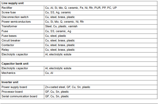
The ACV700 frequency converter is mainly composed of an incoming line unit (LSU), a capacitor bank unit (CBU), and an inverter unit (INO). The materials for each part are as follows:
Unit, main components, core materials
Incoming unit rectifiers, fuses, circuit breakers, etc. made of copper (Cu), aluminum (Al), steel (Fe), ceramics, plastics (PP, PC, PVC), silver (Ag), nickel (Ni), etc
Aluminum (Al) electrolytic capacitor unit, electrolytic solution
Inverter unit power semiconductor, circuit board and other glass fiber (GF), copper (Cu), tin (Sn), plastic, heat dissipation grease (including silicon, zinc chromium, etc.)
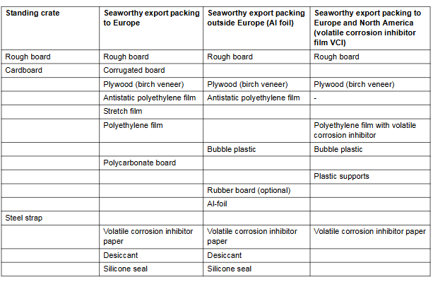
Packaging materials: including wooden pallets, corrugated cardboard, anti-static polyethylene film, VCI rust proof film, etc., all of which are recyclable materials.
Environmental characteristics of production and use
Production management: ABB Oy (Finland)’s production system complies with ISO 9001 (quality) and ISO 14001 (environment) certifications, ensuring environmental compliance in the production process.
Advantages during the usage phase:
Energy saving benefits: By adjusting the motor speed, significant energy consumption can be reduced and operating costs can be minimized.
Optimization control: Accurately adjust speed and torque to enhance process stability.
Extend lifespan: Reduce motor and equipment wear and tear, and lower maintenance requirements.
Product waste disposal and recycling
Handling principle:
Adhere to international and national regulations, prioritize dismantling and separating materials for recycling, and reduce landfill and incineration.
Disassembly method:
Manual disassembly: Separate by material classification (black metal, aluminum, plastic, printed circuit board, electrolytic capacitor, etc.).
Mechanical crushing: Harmful substances (such as electrolytic capacitors) need to be removed first, and then the materials are crushed and sorted using specialized equipment.
Hazardous substance control:
Compliant with the EU RoHS II directive, restricting the use of harmful substances such as lead and mercury, with specific reference to the ABB List of Prohibited and Restricted Substances.
WEEE compliance requirements:
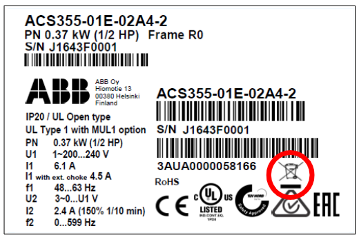
The product is labeled with the “Wheelie Bin” recycling label (with a horizontal line indicating production after 2005), and must be processed through dedicated recycling channels. Mixing with ordinary household waste is prohibited.
Recycling examples and environmental information
Typical recycling methods:
Directly recycling and reusing metal materials such as steel and aluminum; Plastic is used for energy recovery (incineration power generation); Printed circuit boards and electrolytic capacitors are treated as electronic waste; Landfilling of ceramic materials.
Further resources:
More environmental policies, sustainable development goals, and material safety data sheets can be obtained through the ABB official website, or local ABB representatives can be contacted for recycling support.
The 40 series and 50 series of Advant Controller 31 are small and medium-sized programmable logic controllers (PLCs) suitable for industrial automation scenarios with 14 to 1000+inputs/outputs, featuring the following core features:
Flexibility and Scalability: Supports local expansion (up to 6 binary or analog expansion modules) and remote expansion (up to 31 slave units connected via CS 31 bus), covering single machine control to distributed large-scale systems.
Multi scenario adaptation: widely used in fields such as mechanical control, water treatment, building management, greenhouse environmental regulation, etc., supporting functions such as complex logic control, sequence control, and data processing.
Communication capability: Integrate multiple communication protocols (MODBUS, ASCII, CS 31 bus), support interconnection with upper computer, HMI (such as TC50 display), frequency converter and other devices.
Hardware composition and technical parameters
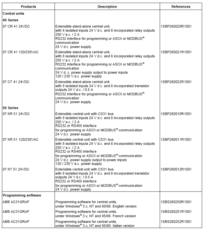
1. Central unit (40 series vs 50 series)
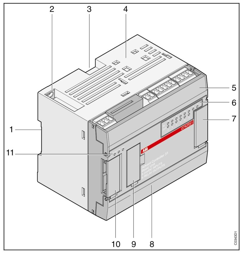
Features 40 series (such as 07 CR 41, 07 CT 41) 50 series (such as 07 KR 51, 07 KT 51)
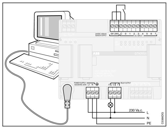
Core configuration includes 8 isolated inputs (24V DC), 6 relay/transistor outputs, 8 isolated inputs (24V DC), and 6 relay/transistor outputs, including CS 31 bus interface
Power supply 24V DC or 120/230V AC 24V DC or 120/230V AC
Scalability up to 6 local expansion modules+31 remote slaves (CS 31 bus)
Communication interface RS232 (programming/ASCII/MODBUS) RS232/RS485 (supporting CS 31 bus master/slave mode)
Memory and Backup 17000 Word User Program Memory, RAM with Battery Backup (40 Days) Same as 40 Series, Supports Data Backup and Recovery
2. Expansion module
Binary extensions: such as XI 16 E1 (16 inputs), XO 08 R1 (8 relay outputs), XC 08 L1 (8 configurable I/O), etc., supporting the expansion of binary signal processing capabilities.
Simulation extension: such as XM 06 B5 (4 inputs+2 outputs), XE 08 B5 (8 inputs), supporting signals such as current (4-20mA), voltage (± 10V), temperature (Pt100/Pt1000), etc., with a resolution of 12 bits.
3. CS 31 bus
Physical layer: RS485 shielded twisted pair, maximum transmission distance of 500 meters (without amplifier) or 2000 meters (with 3 amplifiers).
Communication characteristics: master-slave protocol, supporting up to 31 slave stations, with a maximum transmission rate of 187.5 kbps, using CRC8 verification to ensure data reliability.
Programming and Software
1. Programming software and language
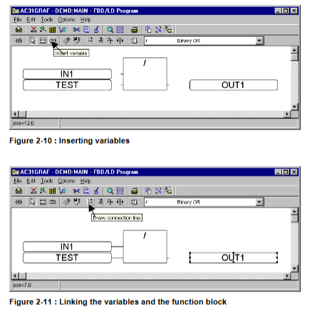
AC31GRAF: Supports Windows system, provides programming languages such as ladder diagram (LD), function block diagram (FBD), instruction list (IL), etc., and is compatible with IEC 1131-3 standard.
Core functions: variable declaration, program editing, compilation, online debugging, parameter configuration (such as cycle time, communication mode).
2. Program Structure
Supports the main program, up to 12 sub programs, and interrupt programs (hardware triggered or periodic), enabling complex logic and real-time response.
Built in rich functional blocks: logical operations (AND/OR), timers (TON/TOF), counters (CTU/VRZ), PID regulation, communication control (MODBUS/CS 31), etc.
Communication and Integration
Core Communication Protocol and Interface
CS 31 bus
Positioning: The core bus of distributed control adopts a master-slave architecture (RS485 standard), supporting communication between remote expansion units and central units.
Technical parameters:
Transmission medium: shielded twisted pair (AWG 24-18), maximum length of 500 meters (without amplifier) or 2000 meters (with 3 NCB/NCBR amplifiers).
Communication speed: up to 187.5 kbps, using CRC8 verification to ensure data reliability.
Connectivity: The master station can manage up to 31 slave stations (remote units, expansion modules, third-party devices such as frequency converters, etc.).
Application scenario: Suitable for workshop level distributed control, such as signal acquisition and control instruction transmission at each workstation of the production line.
MODBUS protocol
Support type: MODBUS RTU (master/slave mode), compatible with industrial standard equipment (such as HMI, PLC, frequency converter).
Interface and configuration:
Physical interface: RS232 (40 series) or RS232/RS485 (50 series), connected through a dedicated cable (07 SK 51/53).
Communication parameters: default 9600 baud, 8 data bits, 1 stop bit, no checksum, can be adjusted through software configuration.
Function: Supports reading and writing coils (01/05 function codes) and registers (03/06 function codes), enabling data exchange with upper level computers (such as SCADA) or HMI (such as TC50 displays).
ASCII protocol
Positioning: point-to-point text communication, used for interacting with ASCII devices such as printers and terminals.
Features: Communication parameters (rate, parity, etc.) need to be configured through SINIT functions, support custom message formats, suitable for simple data printing or instruction transmission.
Integration capability and expansion methods
Native Extensions
Connect binary/analog expansion modules through dedicated interfaces, such as:
Binary extensions: XI 16 E1 (16 inputs), XO 08 R1 (8 relay outputs), supporting up to 6 modules.
Simulation extension: XM 06 B5 (4 inputs+2 outputs), XE 08 B5 (8 inputs), supports signals such as current (4-20mA), voltage (± 10V), temperature (Pt100/Pt1000), etc.
Remote integration
Connect remote units (such as ICMK 14 F1/N1) through CS 31 bus to achieve decentralized I/O acquisition and control, suitable for large equipment or long-distance scenarios (such as workshop cross area control).
Support third-party device access, such as ABB ACS series frequency converters (via NCSA-01 interface), high-speed counters (ICSF 08 D1), etc., communicating through CS 31 protocol.
HMI and upper system integration
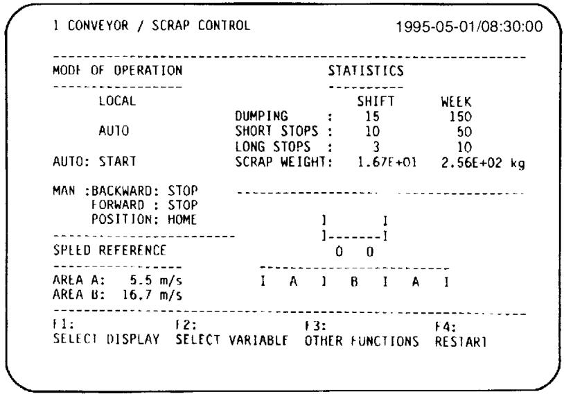
TC50 monitor: Connected via RS232/RS485, supports 128 page display, parameter modification, alarm prompts, and is compatible with MODBUS protocol.
Programming and Monitoring: Program download and online debugging are achieved through AC31GRAF software (Windows environment), which supports real-time data interaction with PC.
Communication optimization and diagnosis
Redundancy and reliability
The CS 31 bus supports media redundancy (dual cables) and bus redundancy (dual master stations), and achieves automatic fault switching through NCBR amplifiers to reduce the risk of communication interruption.
Communication timeout detection: The master station identifies faulty slave stations through CRC checksum timeout mechanism (default 250ms), triggers alarms, and records error codes.
diagnostic function
Error classification: Divided into 4 levels (fatal error, serious error, light error, warning), the specific cause (such as bus disconnection, address conflict) is displayed through the ERR indicator light and software (AC31GRAF) of the central unit.
Communication status monitoring: Real time monitoring of communication health through variables IW 62.15 (CS 31 bus status) and MW 255. x (MODBUS watchdog).
Advant Controller 410 is a medium-sized process controller suitable for binary, regulating, and monitoring control. Its main advantages include:
Comprehensive functionality: supports various functions such as logic control, arithmetic operation, data processing, sequence control, PID regulation, etc., to meet the needs of complex industrial scenarios.
Flexibility and Scalability: Both hardware and software can be flexibly expanded, supporting online configuration and adding modules without interrupting operation.
Strong compatibility: Supports multiple communication protocols (such as MasterBus 300/300E, Advant Fieldbus 100, PROFIBUS-DP, etc.), and can be integrated with I/O systems such as S100 and S800.
High reliability: Supports redundant configurations such as power and communication, with RAM memory backed up by batteries (at least 4 hours) to ensure data security.
Core functions and technical features
1. Control and processing capabilities
CPU and Memory: Based on Motorola 68020 microprocessor (25 MHz), equipped with 4 or 8 MB dynamic RAM with error correction, supporting system program and application program storage.
Programming and Execution: Using ABB Master Programming Language (AMPL), supporting functional block (PC element) programming, program cycle time can be configured (usually 10 ms -2 s, extended 5 ms -32 s).
I/O capacity: Supports up to 4300 I/O points, including analog input (AI), analog output (AO), digital input (DI), and digital output (DO), supporting S100 (local I/O) and S800 (distributed I/O) systems.
2. Communication and Integration
Communication interface: Supports various buses such as MasterBus 300/300E, Advant Fieldbus 100, PROFIBUS-DP, LONWorks, etc., and can connect operator stations, printers, external devices, etc.
Data exchange: Data transmission is achieved through data sets, supporting cyclic and on-demand transmission, and remote communication (such as RCOM/RCOM+, MODBUS).
3. Diagnosis and maintenance
Self diagnosis: equipped with hardware fault detection, communication error monitoring and other functions, displaying system status (such as running, error, timeout, etc.) through LED indicator lights.
Time synchronization: Supports internal clock and external synchronization (accuracy<3 ms), with event time marking accuracy up to 1 ms.
Hardware components
1. Core module
Processor module (PM150V): includes CPU, RAM, program card interface (PCMCIA), submodule slots (supporting communication interfaces, etc.), front panel with status indicator lights and operation switches (start/stop mode).
Power system: Supports 120/230 VAC or 24/48 VDC input, can be configured with redundant power supply (dual power supply+3 voltage regulators) to ensure stable power supply.
I/O system:
S100 I/O: Up to 15 I/O boards, supporting analog, digital, pulse counting, and other signals, placed on the same shelf as the CPU.
S800 I/O: Distributed I/O connected via Advant Fieldbus 100, supporting up to 79 stations per bus and up to 24 modules per station.
2. Expansion and redundancy
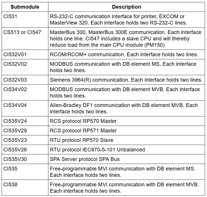
Submodule: supports communication interfaces (such as CI531 for RS-232-C, CI541V1 for PROFIBUS-DP), power regulators, etc., and is hot swappable.
Redundant configuration: Power supply, communication bus, CPU, etc. can be redundant to improve system availability.
Software components
Basic and optional modules
Basic module (QC01-BAS11): includes core PC elements such as logic, arithmetic, and data processing, supporting I/O systems and basic communication.
Optional modules:
QC01-LIB11: Extended process control functions (such as PID regulation, filters).
QC01-LIB12: Advanced process control (such as adaptive regulation, ratio control).
QC01-OPF11: Supports operator station functions such as trend display and alarm management.
AC 450 is a process controller suitable for high demand industrial applications, with the main features including:
Upgrade and compatibility: As an upgrade path for MasterPiece 200, it supports a longer lifecycle and can be fully integrated with System 800xA systems.
High performance and scalability: With high processing capabilities, it is suitable for complex applications and can support process expansion while controlling engineering costs.
High availability: Supports redundant backup of communication, power, CPU, and I/O boards to ensure high availability of the factory.
Multi protocol support: compatible with multiple communication protocols such as MODBUS, Profibus, Masterbus 300/300E, Advant Fieldbus 100, etc., facilitating the construction of optimized control system architectures.
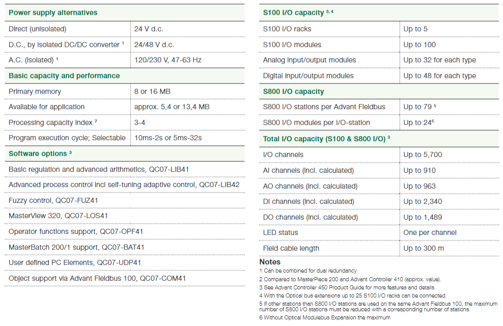
I/O Capacity and Configuration
1. S100 I/O capacity
Supports up to 5 S100 I/O racks and 100 S100 I/O modules.
The maximum number of analog input/output modules is 32, and the maximum number of digital input/output modules is 48.
Note: Up to 25 S100 I/O racks can be connected through optical bus expansion.
2. S800 I/O capacity
Each Advant Fieldbus supports up to 79 S800 I/O stations (if there are other stations on the bus, they need to be reduced accordingly).
Each I/O station can have up to 24 S800 I/O modules (without optical expansion).
3. Total I/O capacity (S100+S800)
Total I/O channels: up to 5700.
Analog inputs (including calculated values): up to 910; Analog output (including calculated values): up to 963.
Number input (including calculated values): up to 2340; Digital output (including calculated values): up to 1489.
Other features: Each channel is equipped with LED status indicator lights, and the longest on-site cable length is 300 meters.
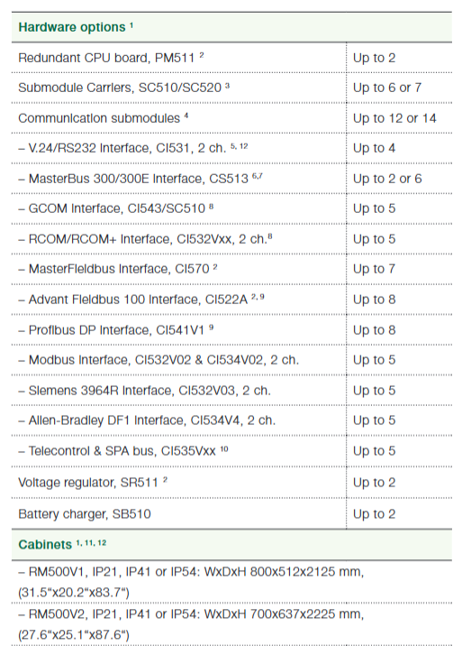
Hardware Options
CPU and Redundancy: Up to 2 redundant CPU boards (PM511), supporting dual redundancy configuration.
Submodule carrier: up to 6 SC520 or 7 SC510, totaling up to 8 modules including CPU.
Communication submodule: up to 12 (with redundant CPUs), supporting multiple interfaces:
V. 24/RS232 (CI531, 2 channels): up to 4;
MasterBus 300/300E (CS513): up to 2 (executed by the main CPU) or 6 (executed by the slave CPU);
Advance Fieldbus 100 (CI522A), Profibus DP (CI541V1): up to 8 each;
Modbus, Allen Bradley DF1 and other protocol interfaces: up to 5 each.
Power supply and auxiliary equipment: up to 2 voltage regulators (SR511), 2 battery chargers (SB510).
Cabinet: Provides RM500V1 (IP21/IP41/IP54, size 800 × 512 × 2125mm) and RM500V2 (IP21/IP41/IP54, size 700 × 637 × 2225mm), which can be combined into multiple cabinet groups.
Efficiency and economy: Robot automation can improve welding efficiency, reduce waste, and improve quality. The investment payback period for single or dual robot units can be as short as 6 months, which is not only suitable for long series production in the automotive industry, but also meets the short series or even single piece production needs of small and medium-sized enterprises.
Usability: Simplify programming and operation through specialized software tools, allowing operators to quickly program and reprogram, reducing implementation time.
One stop solution: Provide a complete arc welding package, including equipment and software, to simplify the procurement process, reduce costs, shorten delivery time, and all components are tested in the laboratory to ensure collaborative work.
Main components and functions
1. Robots
Core models: including IRB 140, IRB 1410, IRB 1600 series, IRB 2400 series, IRB 4400 series, IRB 4450S, etc., with a load range of 5-60kg, a working radius of 0.81-2.55m, and a repeat positioning accuracy of 0.03-0.1mm, suitable for different welding scenarios.
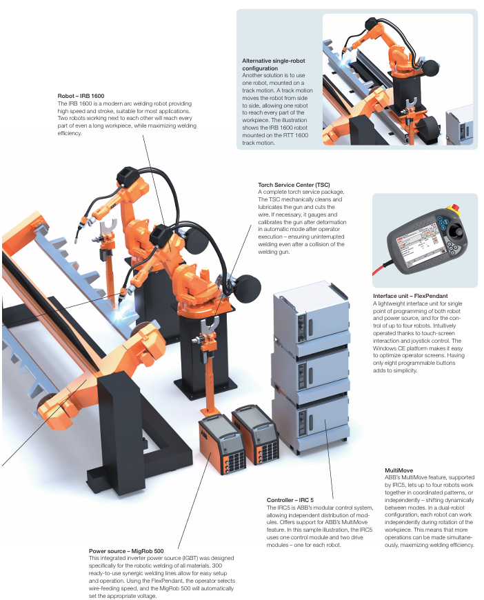
Typical applications: IRB 1600 is fast and has a large stroke, suitable for most applications. Its dual robot configuration can cover long workpieces, and when combined with orbital motion (such as RTT 1600), it can expand the operating range.
2. Power sources
MigRob 500: an integrated inverter power supply designed specifically for robot welding, supporting MIG/MAG welding, with a voltage range of 8-60V and a current of 16-500A. It includes 300 ready-made collaborative welding circuits, and the operator can automatically match the voltage after selecting the wire feeding speed.
RPB series: including RPB 320/420/520, current range 10-520A, supports short arc, spray arc, fast arc and other processes, suitable for different load requirements.
3. Positioners
Classification and Parameters: Divided by model into IRBP R/C/L/A/K/B/D series, with a load capacity of 250-5000kg, a maximum diameter of 1000-3200mm, and a maximum length of 900-5000mm, it is used to fix and rotate workpieces, making it convenient for robots to weld in all directions. For example, IRBP K 750 has a load of 750kg, can rotate axially and rotate itself, making it easy to load and unload workpieces.
4. Controller System&Interface
IRC5 controller: Modular control system, supports MultiMove function, can control up to 4 robots to work together or independently, including control module and drive module, with a protection level of IP54.
FlexPendant: Lightweight interface unit, 7.5-inch screen, supports touch operation and joystick control, programmable with 8 buttons for single point programming of robots and power supply, controlling up to 4 robots.
5. Welding gun system and auxiliary equipment
Welding gun system: including gas cooled PSF 315 M and water-cooled PKI-S/PKI-D series, with a current range of 170-500A, suitable for welding wire diameters of 0.8-2.4mm, PKI 500 D can replace Dresspack without disassembling the welding gun, saving time.
Welding Gun Service Center (TSC): Automatic cleaning and lubrication of welding guns, cutting of welding wires, automatic calibration after collision, ensuring uninterrupted welding.
Track motions: such as IRBT 1003S and RTT series, adapted to different robots, with a speed of 0.8-1.8m/s and a repeat positioning accuracy of ± 0.05-0.15mm, expanding the robot’s operating range.
6. Software products
RobotStudio: a simulation and offline programming software that allows for robot programming to be completed in the office without affecting production, making it convenient for MultiMove programming.
ArcWeld PowerPac (AWPP): A plugin for RobotStudio designed specifically for generating arc welding programs, including ready-made welding templates for easy editing by users.
WebWare: a monitoring system that analyzes production trends, identifies fault causes, backs up robot systems, and accesses them through a web interface.
VirtualArc: Offline prediction and adjustment of welding parameters, simulating arcs to predict welding quality, contour, and defects, optimizing productivity and quality.
Typical Configuration Example
1. Dual station long workpiece welding unit (efficient mass production configuration)
Core objective: To achieve parallel loading, unloading, and welding of workpieces through a dual station design, maximizing robot utilization and suitable for welding workpieces up to 4 meters in length.
Component model/specification and function description
Robot IRB 1600 2 robots work together, with a load of 5-7kg, a working radius of 1.2-1.45m, a repeat positioning accuracy of ± 0.05mm, and high-speed welding to ensure efficiency.
The IRBP K 750 displacement machine has a load of 750kg and supports axial rotation of the workpiece (facilitating full angle welding of the robot) and self rotation (achieving dual station switching). The maximum workpiece length is 4000mm and the diameter is 1400mm.
The MigRob 500 power supply integrates IGBT inverter, supports MIG/MAG welding, with a current of 16-500A and 300 collaborative welding parameters, automatically matching wire feeding speed and voltage.
The welding gun system PKI 500 D water-cooled dual interchangeable welding gun can quickly replace Dresspack (without disassembling the welding gun), adapt to welding wire diameters of 0.8-1.6mm, and has a current of 400A at 100% load duration.
The IRC5 modular control system includes one control module and two drive modules, supports MultiMove function, and enables two robots to work independently or collaboratively.
The TSC welding gun service center automatically cleans and lubricates the welding gun, cuts the welding wire, and automatically calibrates after collision to ensure uninterrupted welding.
Workflow:
When the operator is loading and unloading workpieces at workstation A, the robot is welding at workstation B; After workstation B is completed, the positioner rotates to switch workstations, achieving seamless connection.
2. Single robot track configuration (flexible adaptation to long workpieces)
Core objective: Expand the robot’s operating range through orbit, suitable for welding small and medium-sized batches of diverse long workpieces, and reduce equipment investment.
Component model/specification and function description
The IRB 1600+RTT 1600 orbital robot is installed on the track, with a track speed of 1.06m/s and a repeat positioning accuracy of ± 0.05mm. It can cover workpieces up to 6 meters long.
The RPB 520 power supply has a current of 10-520A and supports processes such as short arc and spray arc. It can output 520A at 80% load duration and is suitable for high-strength welding requirements.
The IRBP 500 L displacement machine has a load of 500kg and a maximum workpiece length of 4000mm. It rotates the workpiece horizontally to match the welding angle of the robot.
The software ArcWeld PowerPac uses the RobotStudio plugin to quickly generate welding programs, simplify parameter settings using preset templates, and shorten programming time.
Advantages: The combination of single robot and track reduces costs, and the coordinated control of track motion and robot ensures consistent welding of long workpieces.
3. Compact single workstation configuration (for small and medium batch production)
Core objective: Small footprint, suitable for scenarios with limited workshop space, balancing flexibility and economy.
Component model/specification and function description
Robot IRB 1410 has a load of 5kg and a working radius of 1.44m, suitable for small and medium-sized workpieces, with a repeat positioning accuracy of ± 0.05mm.
The MigRob 500 power supply features an integrated design that saves space and supports pulse arc welding to ensure the quality of thin-walled welding.
The displacement machine IRBP 250 R has a load of 250kg, a maximum workpiece diameter of 1000mm, and achieves multi angle welding through axial rotation.
Interface unit FlexPendant 7.5-inch touch screen+joystick, single point control of robot and power supply, simplifying operation.
Typical Configuration Example
Applicable scenarios: Small and medium-sized welding of tools, agricultural machinery, etc., optimized production rhythm and reduced downtime through WebWare monitoring system.
Common characteristics of configuration
Software and hardware collaboration: All components (such as robots, power supplies, and positioners) have been tested by ABB laboratory to ensure compatibility and reduce integration difficulty.
Flexibility: Supports offline programming (RobotStudio) and parameter optimization (VirtualArc), quickly adapting to different workpiece switching.
Reliability: The protection level of the core components reaches IP54, adapting to workshop dust and splash environments and reducing maintenance requirements.
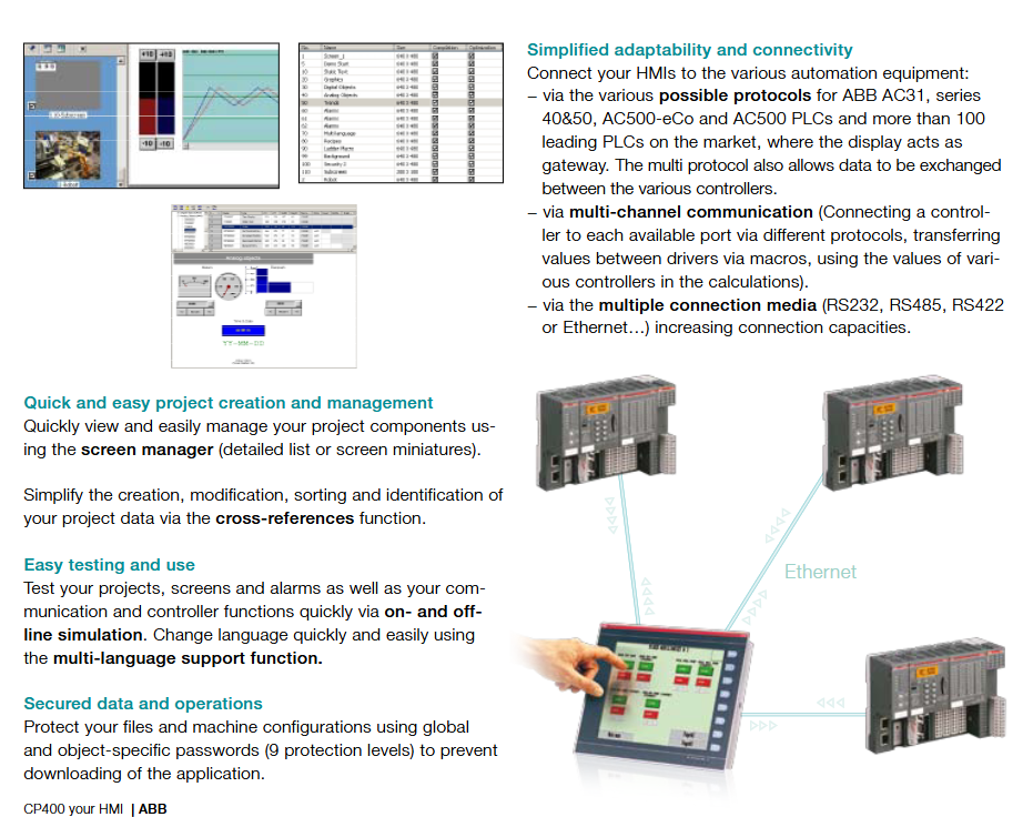
The CP400 series is a high-performance human-machine interface launched by ABB, aimed at improving operational efficiency and productivity in industrial automation scenarios. Its core advantages include:
Simplified development: Supports macro instructions and ladder diagram functions, provides ready-made modules such as arithmetic operations, and can quickly obtain PLC variables through variable import, simplifying the project creation process.
Flexible adaptation: Provides multiple sizes, display types, and functional models to meet different scene requirements, supporting communication with AB MicroLogix, AC31, AC500 and other controllers/PLCs.
Enhance visual experience: Support custom fonts and dynamic GIF import to improve interface aesthetics and interactivity.
Comprehensive compatibility: Compliant with ROHS standards, with a protection level of IP65, suitable for industrial environments, and a working temperature range of 0-50 ℃.
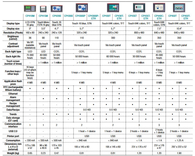
Main models and technical parameters
Model, display characteristics, core configuration, communication and expansion, physical parameters
CP450T-ETH: 10.4 inch touch TFT (64K color), 640 × 480 resolution 8MB flash memory, supports large capacity data storage, 3 communication interfaces, Ethernet, 2USB host+1 device, size 297 × 222 × 52mm, weight 1.90kg, power consumption<1.25A
Programming software and accessory details
programming software
Name: CP400Soft
Order number: 1SBS 260 284 R1001
Function: Used for project development of CP400 series HMI, supporting macro instructions, ladder diagram programming, variable import, online/offline simulation and other functions, simplifying interface design and logic configuration.
TK403, RS232 interface, used for communication with AC31 controllers (40&50 series), 1SBN 260 218 R1001
TK405, RS232 interface, used for AC500 controller communication, 1SBN 260 221 R1001
TK406, RS485 interface, used for AC500 eCo controller communication, 1SBN 260 224 R1001
General characteristics
Hardware compatibility: All cables and programming software are compatible with the CP400 full range HMI and support communication with mainstream PLCs/controllers such as AB MicroLogix, AC31, AC500, etc.
Industrial standards: Compliant with ROHS environmental protection standards, the cables are made of durable materials that are suitable for complex industrial environments.
Positioning and advantages: CS31 is a distributed automation system that simplifies the wiring and implementation of industrial control through a decentralized architecture, reducing costs (up to 80% of wiring costs can be reduced), and is suitable for scenarios with high modular requirements and cost sensitivity. Its core advantages include modular design, flexible expansion, powerful diagnostic capabilities, support for online expansion units, and remote I/O channels that can be programmed like centralized devices.
Composition structure: It consists of a central processing unit (CPU), a remote input/output unit (I/O), and an RS485 twisted pair bus. The central unit can be installed in the control cabinet, while the I/O unit can be installed nearby sensors and actuators.
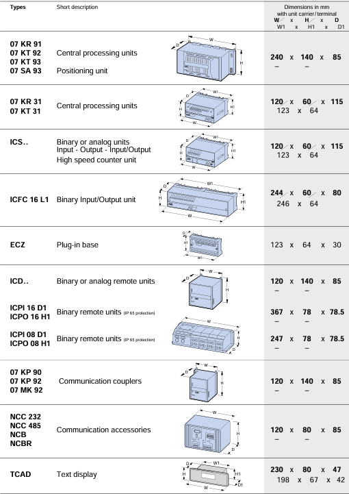
Hardware components
Central Processing Unit (CPU)
Model, main features, power options
07 KR 31 2K: User Program (EEPROM), 12 channel 24VDC input, supports high-speed counting (10kHz), RS485 bus 24VDC, 120VAC, 230VAC
07 KT 31: Similar to 07 KR 31, the output is 8-channel 24VDC/0.5A transistor output 24VDC, 120VAC, 230VAC
07 KR 91:7K FLASH EPROM, 20 channels of 24VDC input, 12 channels of relay output, supporting advanced functions such as PID 24VDC, 115/230VAC
07 KT 92:14K FLASH EPROM, 4 analog inputs (12 bits), 2 analog outputs (12 bits), supporting ARCNET 24VDC, 120/230VAC
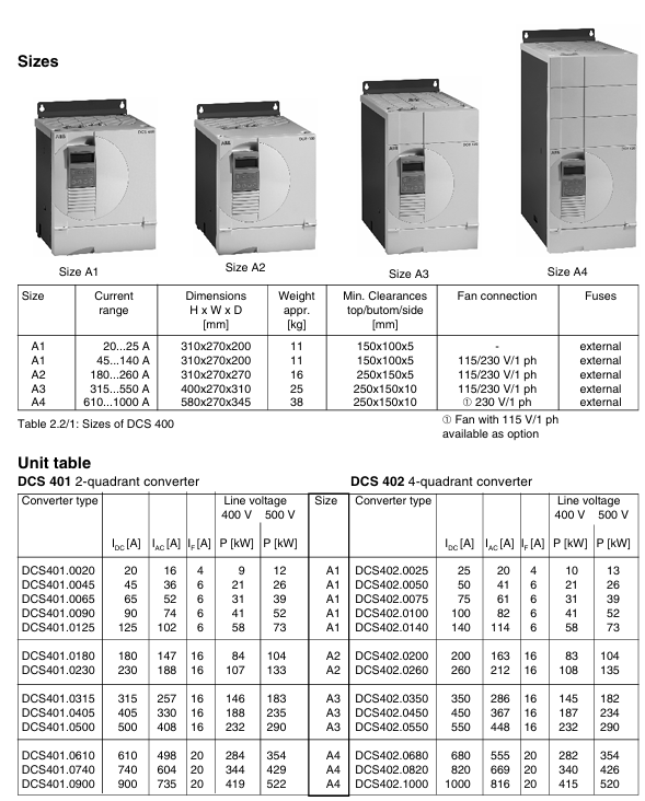
Positioning and Application: A new generation compact DC drive device with a rated current of 20-1000A and a power of 9-522kW, suitable for 230-500V AC power supply and widely used in industrial machinery drive scenarios.
Core advantages: Combining the ease of use of analog transmission with the advantages of digital transmission, compact size, easy installation, integrated exciter (including fuses and reactors), using IGBT excitation technology without the need for voltage adaptation transformers, supporting guided debugging and application macro configuration, improving efficiency and reducing errors.
Technical Parameter
Power and Environment:
Three phase power supply 230-500V, allowable ± 10% deviation, frequency 50/60Hz; electronic power supply 115-230V, allowable -15%/+10% deviation.
Working temperature: rated current+5~+40 ℃, power module+40~+55 ℃; Storage temperature -40~+55 ℃, transportation temperature -40~+70 ℃; Relative humidity of 5-95% without condensation.
Structure and size:
Divided into four sizes A1-A4, weighing 11-38kg, with a protection level of IP00 (power module), ventilation space needs to be reserved for installation (such as 150mm and 100mm above and below A1).
Overload capacity: Depending on the load cycle (DC I-DC IV), it supports 150% -200% overload, with a duration ranging from 10 to 120 seconds.
Cooling and power consumption: Some models require fan cooling (such as A1’s 45-140A with 2 × CN2B2 fans), and power loss varies with load (such as A1’s 20A model losing 49W at 100% load).
FUNCTION
Application macros: preset 8 macro configurations, define digital I/O, reference source and other functions. For example, Macro 1 (standard mode) supports analog speed reference and external torque limitation, while Macro 8 (torque control) uses analog quantity as torque reference.
Control function:
Speed control: supports speed generator, encoder, back electromotive force feedback, with functions such as S-shaped slope, 2 sets of acceleration and deceleration slopes, and automatic demagnetization.
Current/torque control: including current limit, torque limit, I ² t motor protection, supporting switching of second current limit.
Self optimization: It can automatically optimize parameters such as armature current, excitation current, speed controller, etc.
Communication and Interface: Supports RS232, Panel Port, and various fieldbuses (PROFIBUS, MODBUS, etc.) to transmit control commands, reference values, and status information through datasets.
Installation and Connection
Installation steps: Drill holes (92 × 92mm) according to DIN 43700 standard, and fasten the equipment with clamping claw screws to ensure ventilation space.
Wiring requirements:
The power and signal terminals are connected by plug-in screws, with a maximum wire cross-section of 1.5mm ² (2.5mm ² for relays) and a maximum relay output of 250V AC/1A.
Grounding and shielding: The protective grounding needs to be connected, and the shielding layer of the signal cable is fixed on the shielding terminal board.
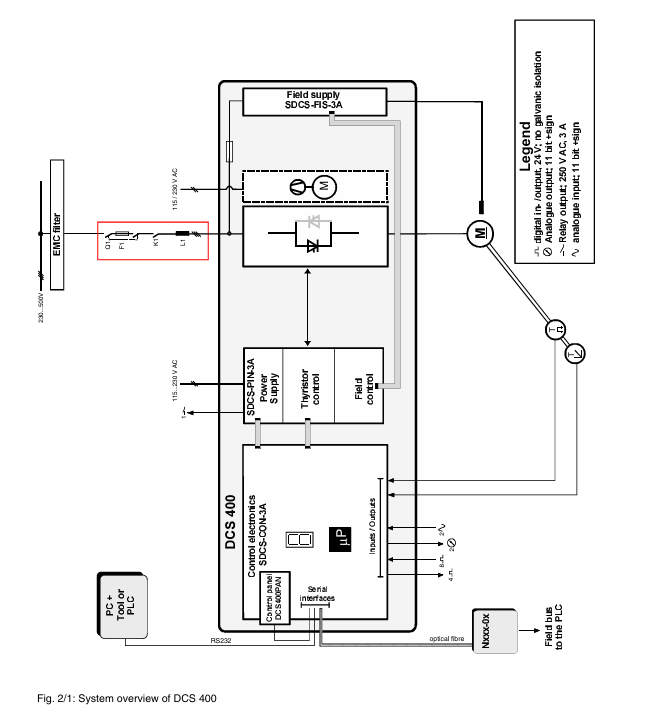
Operation and Debugging
Control panel: parameter settings, fault diagnosis, local operations are implemented through the DCS400 PAN panel, supporting multilingual display and guided debugging.
Debugging process: Use the “Commissioning” function to configure motor parameters (rated current, voltage, speed, etc.) step by step, select control mode, and perform self optimization to ensure system matching.
Troubleshooting
Faults and alarms: Detailed list of fault codes (such as F07 for converter overheating, F09 for main power undervoltage) and alarm codes (such as A02 for main power low voltage), including possible causes and troubleshooting methods.
Diagnostic function: View detailed fault information through the “Diagnosis” parameter, support fault records (up to 16), and facilitate problem tracing.
Security and Authentication
Compliant with CE, UL 508C, CSA C22.2 and other standards, following the Machinery Directive, Low Voltage Directive and EMC Directive, installation must comply with safety regulations (such as power-off operation and correct grounding).
The Digitic 500 is a compact industrial controller suitable for single control loop instrumentation to small and medium-sized process automation, capable of completing simple to complex control tasks. Its documentation system includes installation manuals, debugging manuals, operation manuals, etc., and interface instructions (such as MODBUS) can also be provided upon request.
Basic configuration and functions
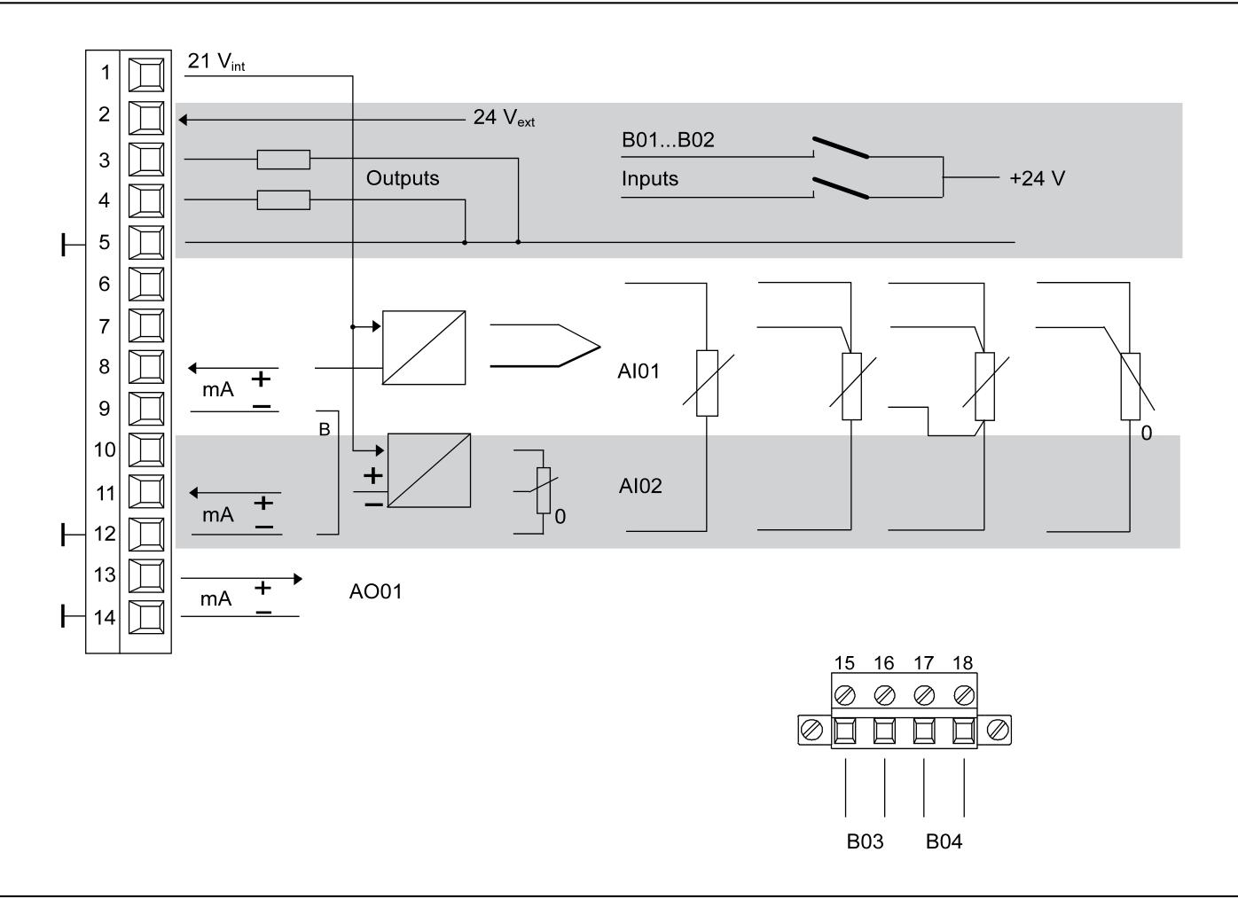
Basic version: Includes 1 universal input (supporting signals such as thermocouples, Pt100, transmitters, etc., with built-in standard sensor linearization table), 1 mA input (can be used as feedforward or setpoint input, and position feedback in stepper controllers), 1 mA output (for positioning signals, etc.), 2 configurable binary inputs/outputs, 2 relays (for executing signals, alarm outputs, etc.), and 4 module slots for expanding functions.
Programmer: Each controller includes a configurable programmer that can preset time related settings, store up to 10 programs, and each program contains 15 segments.
Controller output types: including two-point PID control, hot off cold control, step control, continuous control (optional split range output), etc.
Parameters and Configuration: Parameter settings require entering the password protected parameter level through the menu key; The configuration methods include list configuration (selecting standard functions from the built-in list of the device, which can be operated through IBISRR computer program) and free configuration (allowing customers to specific configurations, which can be added with logic control through the function plan editor).
Installation process
Model identification: Identify the model through the side nameplate.
Installation location: Suitable for front installation in control rooms, control cabinets, and machines, ensuring that it does not exceed the climate and mechanical capacity limits specified in the “Technical Data”.
Installation steps:
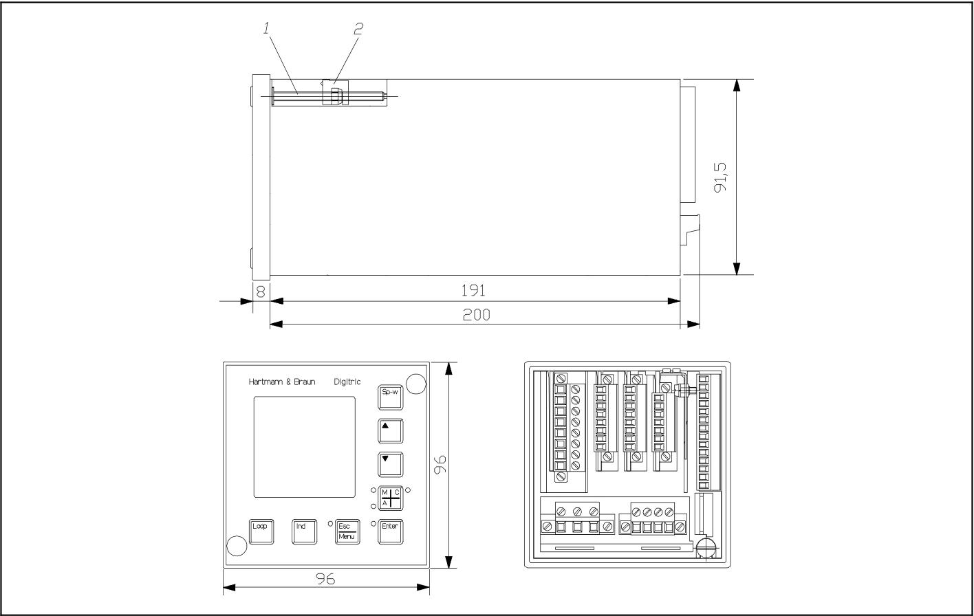
Panel opening: It must comply with DIN 43700 standard, with dimensions of 92+0.8mm × 92+0.8mm. When installed horizontally and tightly, the strip width should be at least 10mm, and at least 40mm ventilation space should be reserved above and below.
Fixed equipment: Remove the front panel dust cover, rotate the clamping claw screw counterclockwise until the clamping claw can be inserted into the panel, push the module into the panel opening, then rotate the screw clockwise to fix it, and finally reinstall the dust cover.
Connection instructions
Signal connection (basic model): using plug-in screw terminals, supporting solid or multi strand wires (maximum wire cross-section of 1.5mm ², maximum relay of 2.5mm ²), including interfaces for power connection, analog input/output, binary input/output, relay output, etc., with relay output up to 250V AC, 1A (cos φ=0.9).
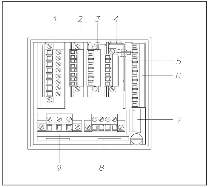
Module and computer connection: The backend includes shielded terminal boards, basic model signal connections, computer ports (configuration interfaces), relay outputs, power supply, and other interfaces.
Module type and configuration
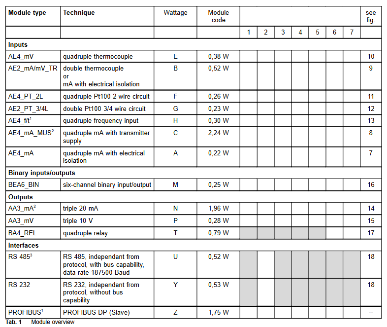
Available modules: including various analog input modules (such as 4 x mA, 2 x mA/thermocouple/mV, 4 x thermocouple, 4 x Pt100, etc.), binary input/output modules (6 channels), analog output modules (3 x mA, 3 x V), digital output modules (4 x relays), interface modules (RS-485, RS-232, PROFIBUS DP slave), etc., with a total of 4 module slots. There are no fixed slot restrictions for module allocation except for interfaces and relays.
Module installation and replacement: Before installation, all hazardous voltages need to be disconnected. Remove the sub component by rotating the twisting screw of the sub component, insert the module into the guide slot from above and install it on the bus PCB, then push back the sub component and lock it; The installation and disassembly of the bus PCB require the use of a screwdriver to operate the snap fastener.
Power supply and grounding
Power connection: Supports 115/230V AC (90-260V, 47-63Hz) or 24V UC. Please follow the relevant power installation specifications and connect the protective grounding conductor before connection. The 24V power supply also needs to be connected to the grounding conductor.
Shielding treatment: A shielding terminal board needs to be installed to fix the shielding layer of the data cable on the contact surface. If there are auxiliary wires in the shielding layer, they can be connected to the terminal.
Technical Parameter
Input: Universal input resolution of 12 bits, measurement tolerance ≤ 0.2% (relative to nominal range), temperature impact ≤ 0.2%/10 ℃; Binary input/output is configurable, with a nominal input level of 24V DC and a maximum output of 100mA.
Output: Analog output 0/4… 20mA (maximum 750 Ω, short circuit and open circuit protection), resolution of 12 bits; The maximum output of the relay is 250V AC, 1A.
Environmental conditions: working temperature 0… 50 ℃, storage temperature -20… 70 ℃, relative humidity ≤ 75% (annual average), short-term up to 95% (slight condensation allowed); Meets EMC related standards and has strong anti-interference ability.
Mechanical parameters: front panel protection level IP65, shell IP30, terminal IP20; The panel size is 96mm × 96mm, the installation depth is 200mm, the weight is 1kg (without modules), each module weighs about 40g, and the relay module weighs about 80g.
Other information
Firmware upgrade and configuration: The firmware can be updated by replacing the IC. To enable free configuration, a specific IC is required. If the password is lost, it can be reset by adjusting the jumper.
Packaging and Accessories: Insulation and buffering should be done for transportation or return packaging. Accessories include various modules, bus PCBs, PC cables, adapters, etc. Please refer to the catalog number when ordering.
EasyLine is a new gas concentration monitoring equipment series launched by ABB, aimed at providing simple, economical, and reliable gas analysis solutions for various application scenarios. Its core advantages include:
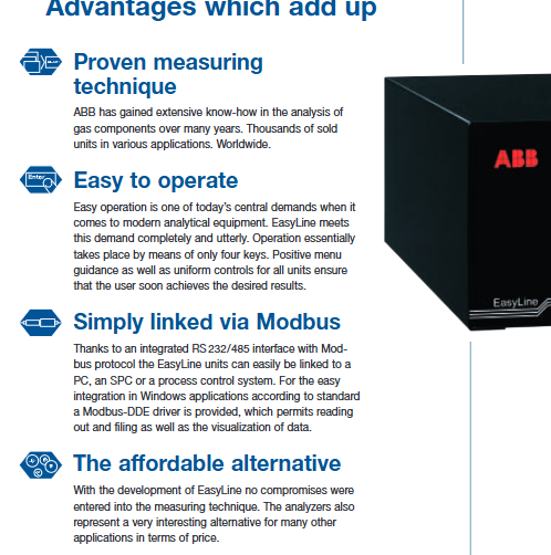
Mature technology: Based on ABB’s years of experience in gas composition analysis, the product technology is mature and has been widely applied worldwide.
Easy to operate: Basic operations can be achieved through 4 buttons, menu navigation is clear, and all device control methods are unified, making it easy for users to quickly get started.
Easy to connect: Integrated with RS 232/485 interface and supporting Modbus protocol, it can easily connect with computers, SPC or process control systems. It also provides Modbus DDE driver for easy data reading, storage and visualization in Windows applications.
High cost-effectiveness: With competitive prices while ensuring that measurement technology is not discounted, it is an economical choice for various application scenarios.
Main product models and technical parameters
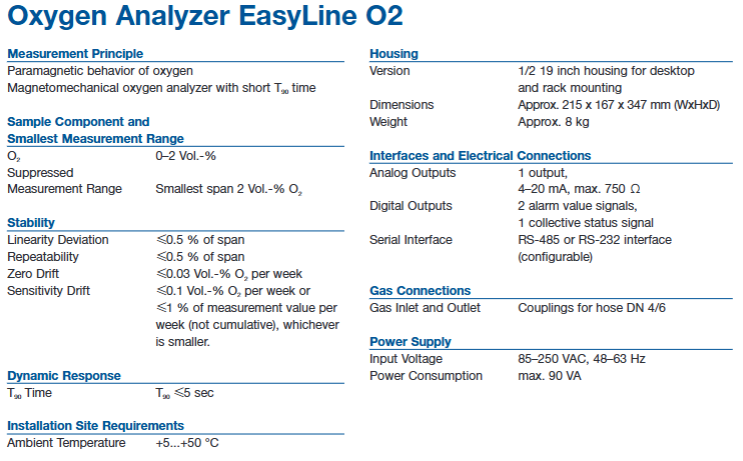
Oxygen analyzer (EasyLine O ₂)
Measurement principle: Based on oxygen paramagnetism, using magneto mechanical principle, with short response time.
Measurement range: The minimum measurement range is O ₂ 0-2 Vol. -%, supporting a suppression measurement range with a minimum span of 2 Vol. -% O ₂.
Stability: Linear deviation ≤ 0.5% of span, repeatability ≤ 0.5% of span, zero drift ≤ 0.03 Vol. -% O ₂/week, sensitivity drift ≤ 0.1 Vol. -% O ₂/week or ≤ 1% measurement value/week (whichever is smaller, not cumulative).
Dynamic response: T ₉₀ time ≤ 5 seconds.
Installation environment: ambient temperature+5…+50 ° C.
Equipment specifications: Adopting a 1/2 19 inch casing, supporting desktop and rack installation, with dimensions of approximately 215 x 167 x 347 mm (width x height x depth) and a weight of approximately 8 kg.
Interface and connection: 1 channel 4-20 mA analog output (maximum 750 Ω), 2 channels of alarm value signal and 1 channel of collective status signal digital output, supporting RS-485 or RS-232 interface (configurable).
Gas connection: The inlet and outlet ports are equipped with DN 4/6 hoses.
Power supply: Input voltage 85-250 VAC, 48-63 Hz, maximum power consumption 90 VA.
Infrared gas analyzer (EasyLine IR)
Measurement principle: Infrared photometer can measure 1 or 2 components. If used in conjunction with an electrochemical oxygen sensor, it can only measure 1 infrared gas component.
Measurement range: The measurable gases and minimum measurement range include CO 0… 500 ppm, CO ₂ 0… 500 ppm, SO ₂ 0… 500 ppm, CH ₄ 0… 500 ppm, NO 0… 1000 ppm. It can also be combined with O ₂ (0… 5 vol. -%) for measurement (specific combinations are shown in the document table).
Stability: Linear deviation ≤ 1% of span, repeatability ≤ 0.5% of span, zero drift ≤ 1% of span/week, sensitivity drift ≤ 1% of measured value/week.
Dynamic response: T ₉₀ time ≤ 2 seconds (O ₂ sensor ≤ 30 seconds).
Installation environment: ambient temperature+5 to+45 ° C (+5 to+40 ° C with O ₂ sensor).
Equipment specifications: Same as oxygen analyzer, 1/2 19 inch casing, size approximately 215 x 167 x 347 mm, weight approximately 8 kg.
Interface and Connection: Each sample component has 1 analog output and 2 digital outputs of alarm value signals, supporting RS-485 or RS-232 interfaces (configurable).
Gas connection: The inlet and outlet ports are equipped with DN 4/6 hoses.
Power supply: Input voltage 85-250 VAC, 48-63 Hz, maximum power consumption of 40 VA.
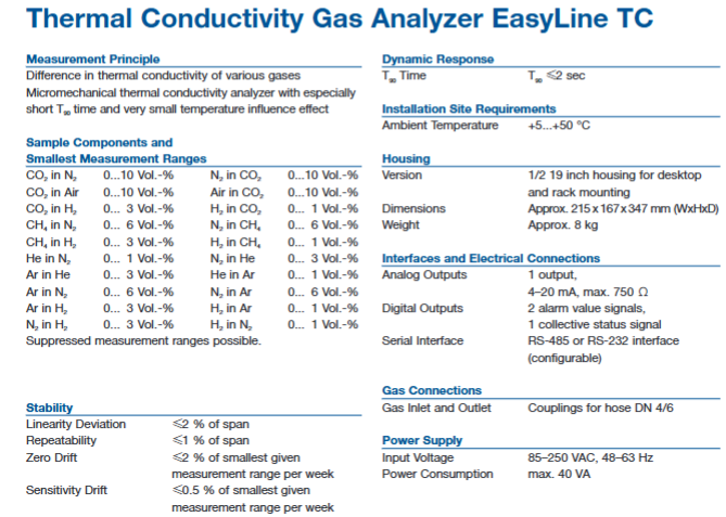
Thermal conductivity gas analyzer (EasyLine TC)
Measurement principle: Based on the difference in thermal conductivity of different gases, micro mechanical thermal conductivity analysis technology is used, which has a short response time and is less affected by temperature.
Measurement range: It can measure various gas combinations and the minimum measurement range, such as CO ₂ in N ₂ 0… 10 Vol. -%, CH ₄ in N ₂ 0… 6 Vol. -%, etc. (see document table for details), supporting suppression of measurement range.
Stability: Linear deviation ≤ 2% of span, repeatability ≤ 1% of span, zero drift ≤ 2% of minimum given measurement range/week, sensitivity drift ≤ 0.5% of minimum given measurement range/week.
Dynamic response: T ₉₀ time ≤ 2 seconds.
Installation environment: ambient temperature+5…+50 ° C.
Equipment specifications: Same as the two analyzers mentioned above, with a 1/2 19 inch casing, dimensions of approximately 215 x 167 x 347 mm, and a weight of approximately 8 kg.
Interface and connection: 1 channel 4-20 mA analog output (maximum 750 Ω), 2 channels of alarm value signal and 1 channel of collective status signal digital output, supporting RS-485 or RS-232 interface (configurable).
Gas connection: The inlet and outlet ports are equipped with DN 4/6 hoses.
Power supply: Input voltage 85-250 VAC, 48-63 Hz, maximum power consumption of 40 VA.
Typical application scenarios
This series of analyzers is widely used, including but not limited to:
Heat treatment (CO, O ₂)
Combustion process (CO)
Biological fermentation tank (CO ₂, O ₂)
Biogas (CO ₂, CH ₄)
Storage bin monitoring (CO, CH ₄)
Wastewater treatment (CO ₂)
Environmental air monitoring for buildings, tunnels, etc. (CO ₂ CO)