Overview: This document provides information on configuring Expert ion ® Technical information for Series C I/O and C300 controllers will be released starting from the Expert R300.
Scope: Includes multiple input and output types, such as 24 VDC digital input, 110 VAC/125VDC digital input, etc.
Definition: Input/Output Terminal Component (IOTA) is a component that accommodates IOM and field wiring connections; An Input Output Module (IOM) is a device that contains most of the electronic devices required to perform specific I/O functions and can be plugged into IOTA.
Characteristics
All Series C components adopt innovative design, support enhanced thermal management, have a unique appearance, and significantly reduce size under the same functionality.
The unique features of Series C I/O include: combining I/O modules and field terminals in the same area without the need for a separate chassis; Two level “detachable” terminals facilitate on-site installation and maintenance; Provide on-site power supply through IOTA, without the need for additional power supply and related manual wiring; Implementing redundancy directly on IOTA without the need for external wiring or redundant control devices.
Innovative design also includes vertical installation for easy wiring, visual prompts for status information provided by the “information circle”, “tilted” design for thermal management inside the cabinet, and short-circuit protection for input and output circuits.
Series C IOTA integrates multiple functions, supporting single redundancy configuration, on-board terminals for process signals, etc. IOM is inserted into IOTA and power is obtained from it. IOTA obtains power from the 24 VDC bus of IOTA carrier.
Series C I/O size
In almost all configurations, the C300 controller and Series C I/O provide useful and maintainable process equipment connections in a smaller space, helping to reduce overall installation costs.
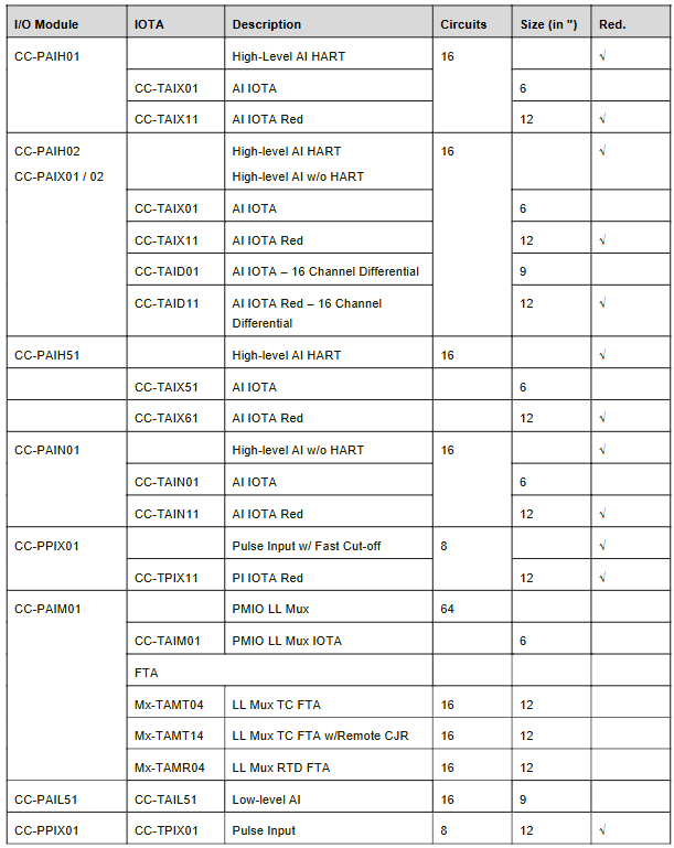
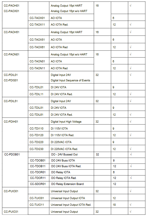
The size of IOTA varies depending on the application, with simulation modules typically having 16 points. Non redundant applications use 6-inch (152mm) IOTA, while redundant applications use 12 inch (304mm) IOTA; The discrete module has 32 points, with 9-inch (228mm) IOTA used for non redundant applications and 12 inch (304mm) IOTA used for redundant applications.
Introduced various I/O module functions, such as advanced analog input/HART input module (16 points), advanced analog input without HART (16 points), etc., and explained the wire specifications accepted by Series C field connectors.
I/O module size
Listed are the IOTA, description, number of circuits, size (inches), and redundancy information corresponding to each I/O module, such as CC-PAIH01 module corresponding to CC-TAIX01 (6 inches, non redundant) and CC-TAIX11 (12 inches, redundant).
Specifications
Detailed specifications of various modules, including functions, notable features, and detailed specification parameters:
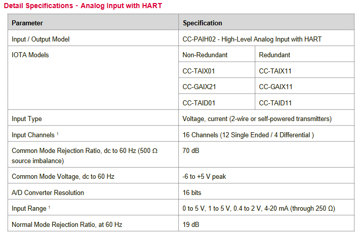
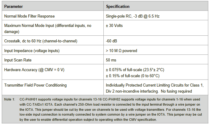
Analog inputs with HART (CC-PAIH01/02, CC-PAIH51): accept high-level current or voltage inputs from transmitters and sensing devices, with a wide range of self diagnostic and optional redundancy features. Detailed parameters include input type, number of channels, common mode rejection ratio, etc.
Analog inputs (CC-PAIX01/02, CC-PAIN01): Similar in function to those with HART, but do not support HART functionality. Parameters include input type, number of channels, etc.
Low level analog (temperature) input (CC-PAIM01, CC-PAIL51): supports temperature input, CC-PAIM01 supports up to 64 channels, using Honeywell PMIO LLMUX FTA; CC-PAIL51 supports 16 channels and is directly supported on Series-C IOTA.
Pulse Input (CC-PPIX01): Provides the ability to monitor various pulse input field values for the Expert C300 controller, suitable for metering and trade handover applications. Parameters include input-output models, channel numbers, frequency ranges, etc.
Analog outputs with HART (CC-PAOH01, CC-PAOH51): provide high-level constant current to actuators and recording/indicating devices, with multiple characteristics and detailed parameters.
Analog output (CC-PAOX01, CC-PAON01): Similar in function to those with HART, does not support HART functionality.
Honeywell C300 related solutions revolve around Expert ® The core of the PKS C300 controller deployment lies in the application of new interfaces and pre assembled cables. IOTAs (Input Output Terminal Assemblies) adopt Weidm ü ller PCB connectors and terminal designs, with flexible connection methods. They can be directly wired to the field or combined with Weidm ü ller’s FTAs (Field Terminal Assemblies) to use pre assembled cables.
Compared to traditional wire to wire wiring, this solution has significant advantages:
Reduce wiring workload: Minimize on-site wiring work by using pluggable connectors and cables.
Quick and easy connection: Pre assembled wiring harnesses can quickly and error free connect IOTA and FTA.
High current switching capability: The isolated digital output FTA has high current switching capacity in a compact design.
Clear identification: IOTA and FTA are equipped with the same Weidm ü ller connector and the same orientation for easy identification.
Excellent flexibility: Pre assembled cables can be made into different cross-sections, with lengths up to 50m.
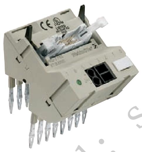
Rich interface options: The Weidm ü ller interface provides multiple functions such as LED indicators, insulators, relays, or fuses, suitable for all C300 I/O cards.
2. Selection Guide
The selection guide aims to help users quickly and conveniently choose suitable products based on their application needs. The steps are as follows:
Step 1: Select the IOTA to use.
Step 2: Determine the number and type of cables required for the connection.
Step 3: Choose the interface that is most suitable for the application.
Taking CC-TDIL01 as an example, there are multiple options available. For example, option 1 can choose pre assembled cable C300-32B-320B (2 pieces) and interface 1221550000 (1 piece); Option 2 can choose pre assembled cables C300-32B-320B (2 pieces) and interfaces 1222980000 (2 pieces).
The selection guide table provides a detailed list of pre assembled cables (including cable type, required quantity per IOTA) and FTA (Weidm ü ller interface) information for different Honeywell IOTAs, covering card type, number of channels, connection method, whether to include LED per channel, whether to include disconnect and test points, whether to include fuse per channel, whether to include external power supply, required quantity per IOTA, and order number.
3. FTA C300 input/output passive interface
This type of interface is used to connect Honeywell C300 digital or analog IOTAs. The following is detailed information for some of the main models:
FTA-C300-32DI-LD: Suitable for CC-TDIL01 and CC-TDIL11, it is a passive input/output interface for digital cards. Technical data includes connection data and functions (control side connection, on-site connection, LED status display, etc.), rated data (working voltage, maximum current per channel, etc.), general data (ambient temperature, storage temperature, etc.), certification (CE, etc.), dimensions (clamping range, installation guide rail, length x width, etc.). There are two types of ordering data: screw connection and tension clamp connection, with corresponding order numbers. The accessories include 5×20 mm 0.63A fuses, etc.
FTA-C300-32DIOHV: Suitable for CC-TDIL01/11, CC-TDOB01/11, CC-TDI110/120/220/230, etc. The technical and ordering data are similar to the above, but there are slight differences in parameters for different application scenarios.
FTA-C300-16AI-TEST: Suitable for CC-TDIL01, CC-TDIL11, CC-TAIX01, CC-TAIX11, etc., it has the characteristics of disconnecting plug and testing point (diameter 2mm, used for voltage and current measurement) and M4 shielding connection. Its technical data and ordering data are also set according to its own functional characteristics.
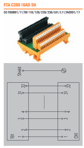
Other models such as FTA-C300-32DO-LD、FTA-C300-32DO-FUSE、FTA-C300-16AI-SH、FTA-C300-16AO-SH、FTA-C300-16AO-TEST Each has its own applicable IOTA model, detailed technical parameters, ordering information, and accessory requirements.
4. FTA C300 isolation interface (per relay)
Taking FTA-C300-32DO-RSLIM as an example, it is suitable for CC-TDOB01 and TDOB11 and is an isolated output interface for digital cards.
Technical data: including connection data and functions (control side connection, pole number, relay type, LED status display, etc.), rated input data (input voltage, input current, working voltage, etc.), rated output data (contact material, working voltage, maximum AC continuous current, etc.), general data (ambient temperature, storage temperature, etc.), certification (CE, etc.), dimensions (clamping range, installation guide rail, length x width, etc.).
Order data: Provide two types of screw connections and tension clamp connections, along with their corresponding order numbers.
Accessories: 5×20 mm 5A fuses, etc.
5. Interconnection cables
Used to connect CS300 cards to Weidm ü ller interfaces, it is divided into Premium series (with connector housing) and Basic series (without connector housing).
Technical data: rated data (wire/shielding capacity, wire/wire capacity), cable characteristics (cable type, material), general data (environmental operating temperature, storage temperature, etc.).
Ordering data: Models and order numbers for different types of cables such as 32 pole, 32 pole+4 pole, etc. The last 3 digits of the cable code indicate the length (e.g. ending with 100 indicates a cable length of 10m).
Cabling system with front-end adapter
Overview
The new Front End Adapter (FAD) is suitable for different PLC I/O cards and, when combined with Weidm ü ller’s interface series, provides a more efficient method for on-site wiring of PLCs compared to traditional wire to wire wiring. Can be connected to standard active or passive interface series, or Weidm ü ller’s MICROSYSTEMS relays or optocouplers.
Its characteristics include:
Wide range: The front-end adapter is suitable for various PLC I/O cards, such as Siemens S7-300 and S7-400, Rockwell Control and Compact Logix, Ge Fanuc and Schneider, etc. Depending on the type of PLC I/O card, the cable can come with or without a casing.
Simple and safe: With the help of plug type connectors and cables, on-site wiring work is minimized to the greatest extent possible, with no wiring errors. Due to the use of a cable system instead of a single wire, the wiring inside the cabinet is clear.
High flexibility: FAD and pre assembled cables can connect multiple interfaces, and Weidm ü ller’s interface series features interesting functions such as LED, fuse, disconnect device, relay, and optocoupler with manual coil connection (optional). The individual modules of the MICROSYSTEMS series can be assembled directly in groups of 8 and connected to the PLC through standard cables and corresponding PLC front-end adapters.
Time saving: Reduce planning and design time, and minimize the time required for debugging and troubleshooting.
FAD Selection Guide
1. General FAD selection table
Select the corresponding PLC front-end adapter (FAD), pre assembled cable (PAC), and interface module group based on the PLC manufacturer, PLC I/O card connector type, analog or digital I/O. For example, the Siemens S7-300 has an input/output card with a 20 pole connector, the FAD corresponding to the digital card is 1127840000 FAD S7/300 HE20 UNIV, the pre assembled cable is 7789806LLL, and the interface module group is RSF 20 GROUP.
2. Specific FAD selection table
Select the corresponding PLC front-end adapter (FAD), pre assembled cable (PAC), passive module, and interface module (relay module/optocoupler module) based on the PLC manufacturer, PLC I/O card, and required on-site system. For example, the 6ES7 321-1BH01-0AA0 card of Siemens S7-300 has an interface corresponding FAD of 1127850000 FAD S7/300 HE20 16 DIO, a pre assembled cable of 7789806LLL, and a passive module group of H2016 GROUP.
FAD front-end adapter for Siemens S7-300 and Rockwell Control Logix
1. FAD front-end adapter for Siemens S7-300
Suitable for Siemens S7-300 cards with 20 and 40 poles, such as FAD S7/300 HE20 UNIV、FAD S7/300 HE20 16 DIO、FAD S7/300 HE40 UNIV、FAD S7/300 2XHE20 32DIO、FAD S7/300 HE40 32DIO Wait.
Taking FAD S7/300 HE20 UNIV as an example, the technical data includes connection data (connection with the card, on-site connection), rated data (working voltage, maximum current per channel, etc.), general data (ambient temperature, storage temperature, etc.), certification (CE, etc.), dimensions (length x width), etc., with corresponding order numbers and applicable PLC card models.
2. FAD front-end adapter for Rockwell Control Logix
Suitable for Rockwell Control Logix cards with 20 and 36 poles, such as FAD CLTX HE20 UNIV、FAD CLTX HE20 16DI、FAD CLTX HE20 16DO、FAD CLTX HE40 UNIV、FAD CLTX 2XHE20 32DI、FAD CLTX HE40 32DI、FAD CLTX 2XHE20 32DO、FAD CLTX HE40 32DO Wait.
Taking FAD CLTX HE20 UNIV as an example, the technical data includes connection data, rated data, general data, certification, dimensions, etc., and there are corresponding order numbers and applicable PLC card models.
5、 RSF PLC – Passive interface for digital signals
A passive interface used for transmitting 32 digital input/output signals, including 1-wire, 2-wire, and 3-wire digital signals.
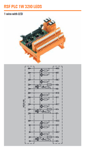
1-wire digital signal interface: such as RSF PLC 1W 32IO, with signal grouping by byte (selected by jumper), selectable switching by positive or negative signal (selected by jumper), optional status indicator (LED) displaying working status and voltage, screw or tension clamp connection, and other features. Technical data covers connection data and functions, rated data, general data, certification, dimensions, etc., and has corresponding ordering data and accessory information.
2-wire digital signal interface: such as RSF PLC 2W 32IO, with characteristics and technical data similar to 1-wire, and adjusted parameters for 2-wire transmission mode.
3-wire digital signal interface: such as RS F40 NIT32 LMZF, which also has corresponding features, technical data, ordering data, and accessory information.
6、 RSM – Isolation Interface for Digital Signals
A relay digital output interface used to transmit electrical signals between PLC and the field through SIM cable or front-end adapter FAD, including interfaces for 16 and 32 isolated digital signals.
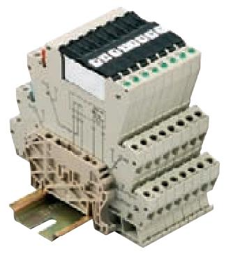
16 isolated digital signal interfaces: such as RSF40 16 RS OUT, with electrical insulation (using pluggable relays, interchangeable with solid-state relays), status indicators (LEDs), screw or tension clamp connections, and other features. Technical data includes connection data and functions, rated input data, rated output data, general data, certification, dimensions, etc., and corresponding ordering data and accessory information.
32 isolated digital signal interfaces: such as RSM-32 PLC C 1CO, with enhanced insulation between input/output (basic insulation between contacts), status indicators (LED), screw or tension clamp connections, etc. Technical and ordering data are also set according to their own characteristics.
MICRO – INTERFACE Solution
1. Overview
MICRO – PLC adapter is used to connect MICROSELES series relays and optocoupler modules to PLC or other controllers through pre assembled cables. The adapter is formed by a 15 pole SUB-D connector or a 10 pole ribbon cable, which can be connected to a set of 8 MICROSYSTEMS relay/optocoupler modules (with screws or tension clips).
2. Selection guide for different brands of PLCs
be directed against GE Fanuc 90 – 30、RX3i、OMRON CJ1W、Rockwell Compact Logix、Control Logix、Schneider M340、MICRO – PREMIUM、Siemens S7 – 300/ET – 200M、S7 – 400 We provide a detailed selection guide for PLC brands, including manufacturer codes for PLC input/output cards, number/type of channels, order numbers and quantities for standard cables, connection methods (screw or tension clamp connections), order numbers and quantities for MICROADAPTER, and information on corresponding input or output relays.
Comparison with Process Manager I/O: There are differences in non-volatile memory, IOL speed, HART support, master-slave module separation, installation environment, and configuration of memory backup.
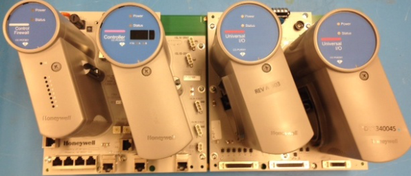
Series C I/O Definition: It is a series of traditional and special function input/output signal interface devices that support local software configuration, share the same external specifications with the C300 controller, and use the same installation system.
Series C I/O Mark II: It is an enhancement of the existing Series C platform in terms of IO modules, related IOTA, IO links, power supply, distribution, and cabinet infrastructure, making it more cost-effective. The design style remains unchanged, but it does not support any PM I/O.
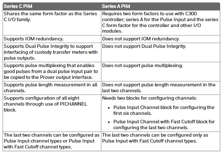
Series C Pulse Input Module (SCPIM): capable of high-precision pulse counting, with 8 input channels, some of which can be configured as dual inputs, and the last 2 channels can also be configured as fast cut-off outputs. It has multiple functions and is different from Series A PIM in terms of external specifications, redundancy support, and other aspects.
Universal Input/Output (UIO) module: 32 channels can be independently configured into multiple types, supporting multiple functions. There are differences in temperature range and channel configuration compared to existing Series C AI, AO, DI, DO modules.
Low level analog input (LLAI) module: used for low-voltage devices, supports 16 channels, accepts millivolt level temperature input, has many characteristics, and differs from AI-LLMUX modules in terms of channel quantity and other aspects.
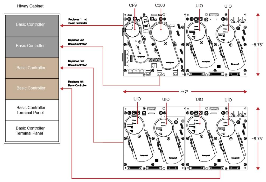
Overview of Universal Horizontal Input/Output (UHIO): It can replace the TDC 2000 basic controller and expansion controller, and introduces the mapping, functions, hardware, differences from Series C IOTA, and certification related content with CB/EC rack.
Series C I/O Planning and Design
General planning reference: Referring to relevant planning documents, introduce the appearance of Series C I/O and the functional characteristics of various modules.
Compared to the C300/CN100 topology structure, it follows certain topology rules, involving redundancy, switching, initialization, number of I/O links, performance, capacity, and other aspects.
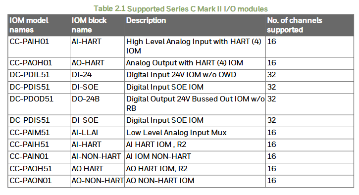
Supported Series C I/O modules: List various module models, names, descriptions, and compatibility matrices, differences between different module models, identification methods, redundant configuration considerations, and lifecycle changes.
Supported Series C I/O options: including multiple options, as well as checking I/O libraries, IOM function blocks, channel function blocks, defining module inclusion relationships, and calculating UIO temperature derating and internal dissipation.
I/O link performance specifications: Introduces the concept of link units, transmission rates, as well as link unit utilization, reducing I/O link traffic, event collection, PV, and reverse calculation scanning.
Universal Input/Output Module 2 (UIO-2): In addition to all the functions of UIO, it also has enhanced features, which differ from UIO-1 in multiple aspects.
Series C I/O installation and upgrade
Installation statement: Emphasize that equipment installation must comply with relevant electrical specifications, pay attention to electrostatic discharge protection, and ensure safe operation in hazardous areas.
Installing Series C IOTA onto the carrier: Certain prerequisites must be met and specific steps must be followed for installation.
Installing the I/O module to IOTA: There are corresponding prerequisites and installation steps, and attention should be paid to the use of screws during installation.
Grounding and power considerations for IOTA board: Introduces the connection and power testing methods and precautions for IOTA board.
Connecting IOM and field devices through I/O terminal components: illustrates the relationship between IOM types and auxiliary hardware, and related tables.
Power supply for Series C system: The power system provides multiple functions, similar to the Process Manager power system.
Series C IOTA board fuse: All IOTAs must contain at least one fuse, and the relevant properties are described.
Series C IOTA Pin Allocation
Detailed introduction of various IOTA models, including analog input, output, digital input, output, low-level analog input multiplexer, speed protection module, servo valve locator module, universal input/output, etc., involving terminal block wiring, field wiring, module protection, allowed wiring resistance, board connection, and other contents.
Series C PIM Connection
Connection diagram: shows the various components and signal processing flow of PIM connection.
On site device output stage types: Introduces various output stage types and their compatibility with PIM.
PIM resistor bias terminal block: used for installing appropriate bias resistors, introduces related operations.
Definition and allocation of pins for each terminal block: including signal definition and pin allocation for TB1, TB2, TB3, and TB4.
Pulse verification enabled: Select the flow to be verified in Control Builder.
Connection with other devices: Introduces the connection methods with ST500 dual pulse simulator, dual current devices, other sensor types, as well as input threshold selection and recommended cable types.
Series C Universal Horizontal Input/Output (UHIO) Components
Introduced the system and grounding audit checklist for horizontal C300/CF9 IOTA, horizontal UHIO IOTA, I/O connectors, TDC 2000 system, UHIO components, installation, general regulatory compliance, COTS AC-DC power supply, protective grounding, and environmental characteristics.
Universal Input/Output (UIO) module for rail installation
Advantages: Low space consumption, high cost-effectiveness, and simple component relocation.
Physical description: Introduces the composition of the components and the model, size, weight, and other information of some components.
Input/Output Link (IOL) Management: Supports specific UIO IOTA versions and DIN rail installations, and introduces relevant cables.
Single mode FOE: It is a necessary component for installing UIO on rails, and its component options, installation positions, etc. are introduced.
System wiring: It demonstrates the end-to-end connection of UIO modules installed on rails in a single cabinet and adjacent cabinets.
Power requirements: Powered by a+24VDC remote industrial grade power supply, including voltage range, power consumption, related protection, wiring, fuse terminal blocks, and circuit breakers.
Institutional certification: Possessing certifications such as CE, CTick, HAZLOC, etc.
Environmental conditions: Clearly defined environmental parameters such as temperature and humidity for work and storage.
Module assembly, installation, connection, disassembly: Detailed introduction of relevant steps and precautions.
Replaceable spare parts: lists the models and names of some replaceable spare parts.
Reference for Series C I/O Configuration Form
Determine redundancy: IOM blocks represent hardware instances of I/O modules, configurable redundancy, and generate system events and alerts.
Switching and secondary readiness: Switching is the process of a secondary module becoming a primary state, and the readiness state of the secondary module determines whether it can take over control functions.
Fault conditions and switching: Some faults may cause switching, such as primary module power failure, while others may not.
Configuration tool: Creating control policies using the Expert Control Builder requires multiple operations, and the IOM must be present during configuration loading.
Each tag configuration: detailed introduction Main、Server History、Server Displays、Control Confirmation、Identification、QVCS、Calibration、HART Status The parameter configuration method and content of the waiting tab.
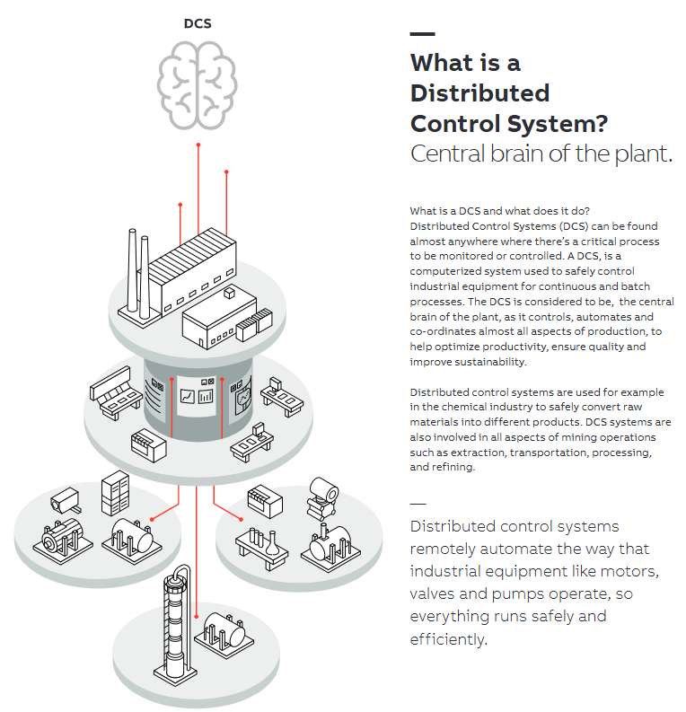
Definition: Distributed Control System (DCS) is a computerized system used for safe control of industrial equipment in continuous and batch processes, and is considered the “central brain” of a factory.
Function: Control, automate, and coordinate almost all aspects of production to help optimize productivity, ensure quality, and improve sustainability. It can remotely realize the automation operation of industrial equipment such as motors, valves, pumps, etc., ensuring their safe and efficient operation. It is widely used in industries such as chemical and mining, such as safe conversion of raw materials in the chemical industry, mining, transportation, and other links.
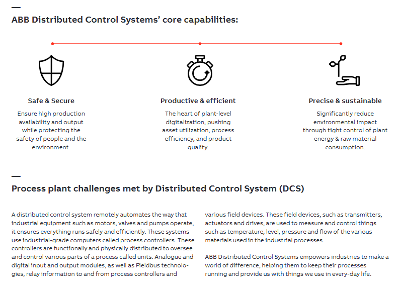
The core capabilities of ABB distributed control system
Safe and reliable: Ensure high production availability and output while protecting personnel safety and the environment.
Efficient and high-yield: As the core of factory level digitization, it improves asset utilization, process efficiency, and product quality.
Precise and sustainable: By strictly controlling factory energy and raw material consumption, the environmental impact is significantly reduced.
Process factory challenges addressed by DCS
Utilizing industrial grade computers known as process controllers to achieve remote automation control of industrial equipment. These controllers are functionally and physically distributed, used to supervise and control various parts of the process (referred to as units).
Analog and digital input/output modules, as well as fieldbus technology, transmit information between process controllers and various field devices. On site devices such as transmitters, actuators, and drivers are used to measure and control the temperature, liquid level, pressure, and flow rate of various materials used in industrial processes.
Safety specifications are generally applicable to control system handling. Instructions and warnings related to a specific subject or operation of the product.
The following norms must be strictly observed:
must strictly comply with the technical specifications and typical applications of the product system
Personnel training: Only trained personnel shall install, operate, maintain or repair the product system. must
Provide guidance and explanation of the situation in danger areas to these personnel.
Unauthorized changes: Changes or structural changes to the product system may not be made.
Maintenance responsibility: Must ensure that the product system is used only under appropriate conditions and in full fitness for use.
Working environment: The user must meet the specified environmental conditions:
Safety regulation
The following safety provisions of EN 50110-1 shall be fully complied with when handling product systems (maintenance) :
1 Disconnect completely.
2 Secure to prevent reconnection.
3 Verify that the installation is complete.
4 Ground and short-circuit the device.
Warning: Only qualified maintenance personnel can remove and insert the module. In order to ensure the personal safety of the operator, before each pulling out or inserting, you must
Disconnect the power supply and ensure that there is no voltage on all terminals at the back, and the product is effectively grounded with the ground screw at the back.
Safety Warning: It is emphasized that only qualified electricians can install equipment. There is dangerous voltage present, and after disconnecting the power supply, it is necessary to wait for at least 5 minutes before opening the cover. The equipment is not repairable on site, and in case of malfunction, the supplier should be contacted for replacement. It also mentioned precautions such as automatic restart, parallel power supply of control terminals, parameter modification affecting device functionality, and high temperature of heat sinks.
Installation related
Installation environment: When using the station, install at an altitude of 0-1000 meters (100% power) and 1000-2000 meters (power and current decrease by 1% for every 100 meters); The ambient temperature is 0-40 ° C (0-30 ° C at 16kHz switching frequency), and the power and current need to be reduced to 80% (4kHz switching frequency) at a maximum of 50 ° C; Relative humidity<95% (no condensation), avoid conductive dust, etc., and the installation site should be clean and dry. The storage and transportation temperature is -40-70 ° C.
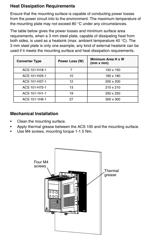
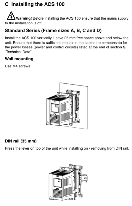
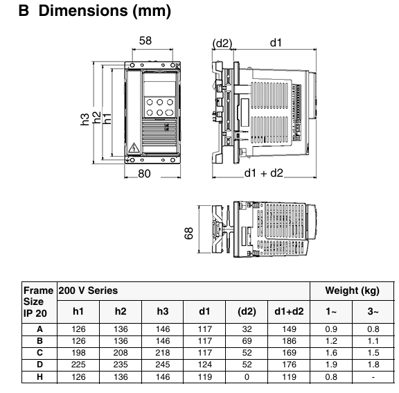
Size and installation: Frequency converters with different frame sizes (A, B, C, D, H) have different size parameters, including height, width, depth, and weight. The installation methods include wall mounting (using M4 screws), DIN rail (35mm), flange installation, etc. The frame H (without heat sink) needs to be installed on a specific metal surface and meet the heat dissipation requirements. During installation, a certain space should be ensured to facilitate heat dissipation.
Removal and installation of cover plate: Press the four snap buttons at the top and bottom corners to remove the cover plate. Before installation, reset the cover plate and then turn on the power.
Cable connection: Clearly define the connection requirements for power input, motor output, DC bus, protective grounding and other terminals. Motor cables need to be shielded and routed separately from control and power cables to avoid electromagnetic interference. Follow local cable cross-section standards, and control and power terminals have different wire diameters and torque requirements.
Terminal interface and warning stickers: Terminal interfaces include power, control, communication, and other terminals, and warning stickers in the corresponding language should be pasted at designated locations.
Technical parameters and protection functions
Technical parameters: divided into standard series and non heat sink series. Different power inverters have detailed parameters in terms of input voltage, continuous output current, maximum output current, switching frequency, protection limits (overcurrent, overvoltage, etc.), maximum length of motor cables, terminal wire diameter, fuses, power loss, etc.
Protection function: It has overcurrent, overvoltage, undervoltage, overheating, output ground fault, output short circuit, input phase loss, power loss tolerance (500ms), I/O terminal short circuit protection, long-term overcurrent limit trip (110%), short-term current limit (150%), motor overload protection, etc. The LED indicator light will display the corresponding alarm and fault status.
Programming and Operations
Control Panel (ACS 100-PAN): Can be connected and removed at any time, supports parameter copying to other ACS 100 of the same software version, has local (LOC) and remote (REM) control modes, can display output frequency, current, etc., and can be started/stopped, direction switching, parameter setting and other operations through buttons.
Configuration switch (S1): Used to configure the I/O configuration of motor rated frequency, acceleration/deceleration ramp time, and digital input. Position 0 is the default, and if using the control panel, it needs to be set to 0. Its position is read when the power is turned on.
Parameter settings: Contains multiple parameter groups, involving actual values and states, motor values and limits, drive control, input/output, monitoring, etc. Some parameter modifications are limited by startup status and configuration switch positions, and can be viewed and set through the control panel.
Menu function: It can restore factory default settings, copy parameters between the panel and the drive, etc. It needs to be operated when the drive is stopped and the local control, configuration switch is set to 0, and parameter lock is released.
Diagnosis and fault handling
Alarm and fault codes: List the codes and descriptions of various alarms (such as parameter upload/download failure, operation not allowed during startup activation, etc.) and faults (such as overcurrent, DC overvoltage, etc.). Alarm and fault information can be cleared through the control panel buttons, and some faults require power-off reset.
Safety Warning: It is emphasized that equipment installation must be operated by qualified electricians. There is dangerous voltage present, and after disconnecting the power supply, it is necessary to wait for at least 5 minutes before opening the cover. The equipment is not repairable on site, and in case of malfunction, the factory or authorized service center should be contacted for replacement. Also mentioned are precautions such as automatic restart, parallel power supply of control terminals, and high temperature of heat sinks.
Installation related
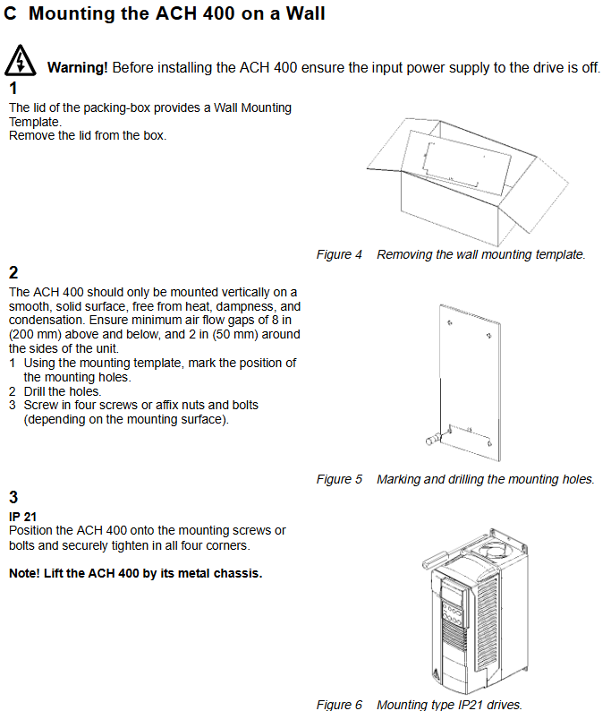
Preparation before installation: Tools such as screwdrivers and wire strippers should be prepared to record the power supply voltage, rated current, and other data on the motor nameplate. After unboxing, it includes a user manual, conduit box, warning stickers, and installation guide. The packaging box cover has a wall mounted template.
Installation environment: When using the station, the ambient temperature is 0-40 ° C (if the temperature reaches 50 ° C, the rated power and current need to be reduced to 90%), the installation altitude is 0-1000 meters (100% power), 1000-2000 meters (1% reduction per 100 meters), and the relative humidity is less than 95% (no condensation). It needs to be installed indoors in a controlled environment, with protection levels of IP21/NEMA Type 1 and IP54/NEMA Type 12, and IP54 protection against dust and light water spray. The storage and transportation temperature is -40-70 ° C.
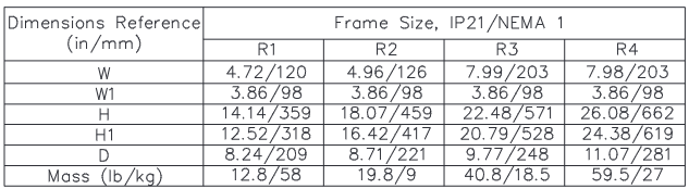
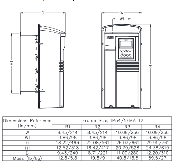
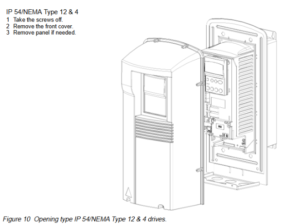
Size and Installation: Drivers with different protection levels and frame sizes have different sizes. The width, height, depth, and quality parameters of each frame size (R1-R4) for IP21/NEMA Type 1 and IP54/NEMA Type 12&4 are clearly defined. The installation needs to be vertically fixed on a smooth and sturdy surface, ensuring an air flow gap of 8 inches up and down, and 2 inches around. It should be fixed by drilling holes according to the template. For the IP54 model, the front cover and rubber plug need to be removed first.
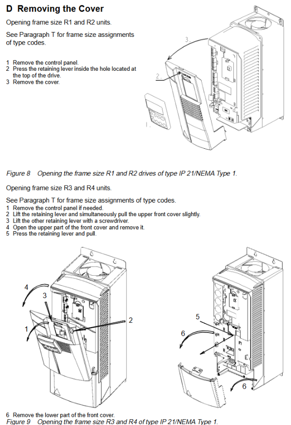
Dismantling and installation of cover plate: The steps for disassembling and installing cover plate are different for drivers with different frame sizes and protection levels. The IP21 and IP54 models of R1, R2, R3, and R4 have their own operating points.
Terminal interface and warning stickers: Terminal interfaces include power, control, communication, and jumper terminals, and warning stickers need to be pasted at designated locations.
Cable connection: Clearly define the connection requirements for each terminal (power input, motor output, DC bus, control wiring, etc.), follow local cable specifications and standards, separate different types of wiring, use shielded cables for control wiring, specific temperature levels for power cables, and mention relevant content on motor protection.
Technical parameters and protection functions
Technical parameters: The rated motor power (square torque and constant torque), input-output current, maximum output current, switching frequency, protection limits (overcurrent, overvoltage, etc.), maximum terminal diameter and screw torque, line fuse and other parameters for different frame sizes are listed in detail, with inputs of 208-240V and 380-480V.
Protection function: It has multiple protection functions such as overcurrent, overvoltage, undervoltage, overheating, output grounding fault, output short circuit, input phase loss, I/O terminal short circuit protection, motor overload protection, output overload protection, locked rotor protection, underload, etc. The LED indicator light will display the corresponding alarm and fault status.
Programming and Operations
Control Panel (ACS-PAN-B): It is an alphanumeric panel with backlit LCD, which can be connected and removed, supports parameter copying, has manual, automatic, stop and other control modes, displays output frequency and other information, and can adjust display contrast.
Menu structure and parameter settings: Contains multiple parameter groups, with basic parameters initially visible, and the full parameter set can be selected through the menu function. Setting parameter values requires entering the setting mode, where default values can be viewed.
Application macros: preset parameter sets, including HVAC Hand Auto, HVAC Floating Point, HVAC PID Control, HVAC PFC Control, etc. After selection, all parameters except for specific parameters will be set as default values. Different macros have different input and output signals and parameter values.
Diagnosis and fault handling
Alarm and fault codes: List the codes, messages, and descriptions of various alarms (such as operation failure, startup activation, etc.) and faults (such as overcurrent, DC overvoltage, etc.). Faults can be reset through the control panel, and some require power-off reset.
Diagnostic counters: Diagnostic counters related to Modbus communication, such as error messages, good messages, etc., can be used to debug fieldbus systems and can be reset through control panel or serial communication.
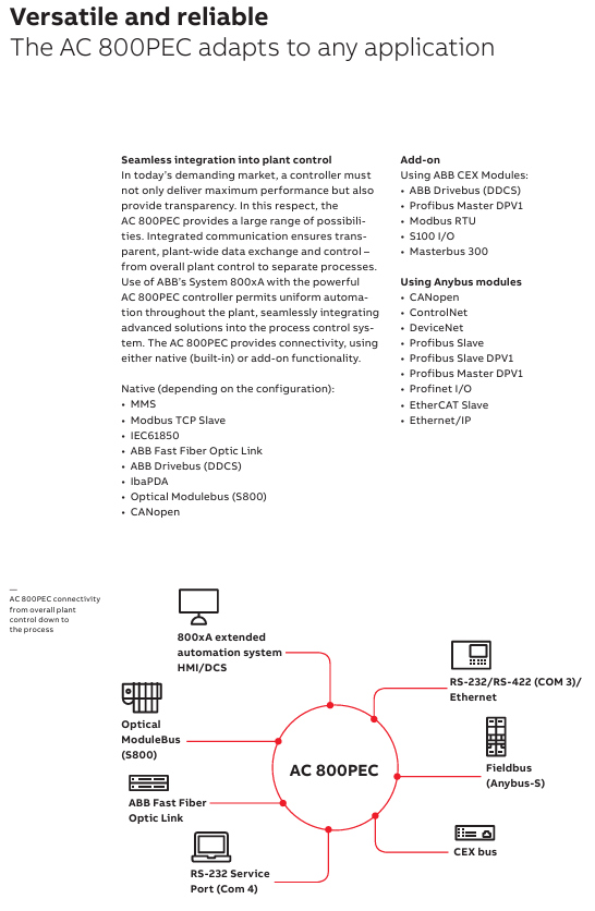
Communication function
Standard Serial Communication: Supports Modbus protocol and can be connected to external control systems. There are two serial communication channels, Channel 1 is a Modbus fieldbus connection and requires activation of relevant parameters.
Communication settings: including station number, communication speed, parity check, etc., which need to be consistent with the main device settings. Control position, output signal source, etc. can also be configured.
Modbus protocol: introduces the protocol related register mapping, exception codes, function codes, control words, status words, actual values, and other related content.
Appendix
Local and Remote Control: Explain the differences and settings between local control (via control panel) and remote control (via digital/analog input, serial communication).
PFC Macro: Introduction to pump and fan control macros, including control principles, PID controllers, relay outputs, I/O extensions, etc.
Dimensional drawing: Provide detailed dimensional drawings of ACH 400 drives with different protection levels and frame sizes.
Taking the technology a step further it is a dualcore processor unit that combines these high speed controls with the low-speed process control tasks usually carried out by separate PLC (programmable logic controller) units. Embed into a robust and flexible system structure with integrated standard communication, the AC 800PEC is unique in the field of industrial process controllers. The AC 800PEC is the ultimate approach for high demands
The AC 800PEC has a unique combination of features for demanding applications:
• Short cycle times, down to 100 μs
• High processing power
• Fast communication and I/O via optical links
• Programming tools:- System engineering with IEC61131-3 languages using ABB’s Control Builder, both Compact and Professional versions available- Product and control development using MATLAB ®/ Simulink ® for model-based design, easily bridging the gap from simulation to implementation
• Full integration into ABB Ability ™ System 800xA
• Innovative and flexible use of FPGAs to include protocols and application functionality in the devices without creating additional processor load
• Optical communication
• Industrial grade hardware with no moving parts
• Long life cycle, easy upgrading
• Robust reliance file system, insusceptible post power loss
Built to control power in Process Industries
ABB has global expertise and technical know-how in processes for industrial, marine and other applications. As a result, the AC 800PEC is a key controller for ABB’s industrial applications, and also for third-party products and systems.
The AC 800PEC is an efficient and flexible controller family. The benefits of short cycle times, fast (input/output) I/O, high-processing power and advanced control using MATLAB ®/ Simulink ®:
• Increases process quality and output
• Saves development and engineering costs
• Reduces the energy consumption of your products
• Shortens time-to-market for your development project
• Saves headcount and resources in engineering and software development
• Enhances Return on Assets (ROA)
• Hardware backup trip integrated with fast
COMBI I/O
The modular structure of the AC 800PEC control system means it can adapt to any application size, from the largest industrial plants and propulsion systems down to very compact products, where space and cost are critical. All over the world, thousands of processors are now proving their worth in a wide variety of extremely demanding applications.
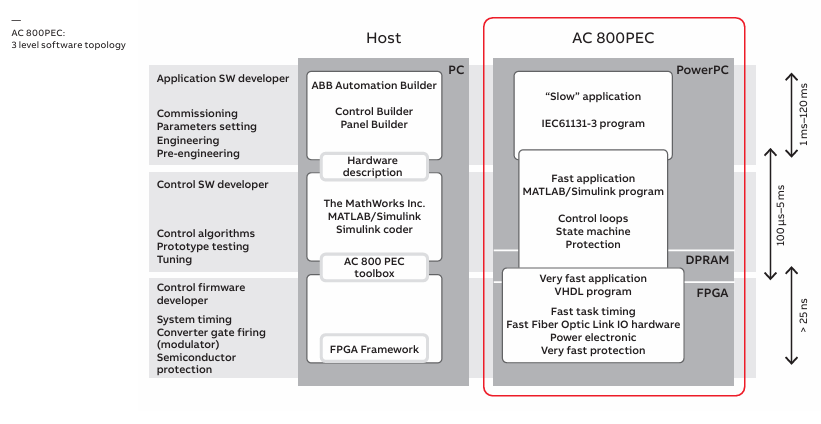
Powerful hardware for efficient, high-speed processing
The AC 800PEC combines the floating-point computing performance of the CPU with the flexibility and high-speed capability of a FPGA.
The system is separated into three performance levels covering different cycle times. Control tasks are allocated depending on their speed requirements:
• Very fast tasks down to 25 ns (nanoseconds for FPGA tasks)
• Fast tasks down to 100 μs (microseconds for Matlab/Simulink tasks)
• Slow tasks down to 1 ms (miliseconds for control tasks)
The hardware architecture of the AC 800PEC is an ideal match to the three-level software structure.
To support the short processing cycle times, the AC 800PEC provides a fast I/O system. Depending on the speed of the I/O connection, it is possible to achieve data throughput times below 100 μs, including the time required to read, process, write and transmit the signal.
Implementation of the AC 800PEC software on the three performance levels provides an exceptional range of control and communication functionality.
The following software packages have been developed to support each of our specific high power rectifier applications.
Aluminium applications
• AC 800PEC Unit controller ↔ AC 800PEC Master controller communication via PEC – PEC fiber optical link (100 μs)
• Units can be controlled independent from master
• Allows emergency operation (full smooth current control, in emergency mode, without AC 800PEC, available only in combination with DCS800 premagnetization)
• Predictive maintenance features can be included
• Open circuit-, over current-, under voltage-, over voltage protection packages included in software- A newly developed OPC (open circuit protection) stand-alone PLC (programmable logic controller), working in combination with the
AC 800PEC Master controller functions or as standalone protection, in case of the master panel maintenance
• Controlled shutdown in an event, not needing an immediate trip → less disturbance for your processes
• Potline load swing detection and load shedding function integrated in application software
• On Load Tap Changer fast tapping function in order to prevent DC current overload during disturbances
• A special potline-to-earth resistance measurement system based on an AC 800PEC family available (PERMS)
• Maximum power regulation- To prevent over-shooting of power consumption and to support your power generators
• Maximum DC voltage regulation for stabilizing your process
Electrical arc furnace applications
• Stable arc detection
• Different control modes (constant current,constant power or constant resistance)
• Fast link to power quality system (PQS)
ELREG (electrode regulation; anode hydraulic system control) features included:
• Electrode manual control (analog or digital)
• Electrode fast lift function (with or without separate fast up valve)
• Automatic arc strike function
• Automatic arc restrike function
• Adaptive electrode control according to furnace behavior or heat stage
• Superimposed integral control circuit
• Voltage fluctuation measurement (stability index calculation)
• Arc-to-roof detection/protection
• Arc-to-roof protection during arc strike sequence
• Hydraulic oil pressure supervision and electrode protection
• Cave-in detection
• High-voltage detection
• Counter pressure valve control logic
• Voltage-to-ground supervision
• Roof voltage monitoring
• Electrode auto raise function after furnace off command (distance or position selectable)
• Blocking valve control
• Electrode speed limitation for electrode and arm protection
• Future features- Automatic proportional valve linearization check- Automatic proportional valve linearization- Dynamic voltage setpoint control for a stable melting process
Chemical applications:
• OLTC step compensation for smooth process control- IDC current step compensation for smooth current change when stepping up
• Power factor compensation by OLTC
• Predictive maintenance features can be included
• Software protection packages including:- DC over current protection- AC over- and undervoltage protection- AC phase unbalance protection- System unbalance protection for 12 pulse systems
• DC earth fault detection available by 3 voltmeter method
• Process pulse block loop with SIL 3 level
• Voltage ride-through in case of incoming voltage dips
Electrowinning industries (copper & zinc):
• IDC current step compensation for smooth current change when stepping up
• Power factor compensation by OLTC
• Predictive maintenance features can be included
• DC overcurrent protection
• AC over- and undervoltage protection
• AC phase unbalance protection
• System unbalance protection for 12 pulse systems
• Master DC current control for parallel rectifier units
• DC open loop detection during start-up
• DC open loop protection during operation
DC power supplies for graphite electrode plants
The graphitisation process demands a large variation of voltage and current from the DC power supply.
• Constant DC power suppy for the process irrespective of changing process resistance – Possible due to the very fast cycle times of AC 800PEC controller.
• Customer tailed process recipes can be added and modified from the operator panel in order to meet the specific customer requirements.
• After adding the corresponding recipes, the rectifier follows the predefined DC current, DC voltage and maximum allowed power setpoints, including all necessary graphitisation specific protection functions.
Scalability in performance
DCS (Distributed Control System)
• Processing cycle times down to 1 ms
• Use of slow I/O
• Programming in Control Builder HMI (Human Machine Interface)
• Processing cycle times down to 1 ms
• Use of slow and fast I/O
• Programming of interface in Control Builder
• Nearly all common field busses supported
• Hardware time stamping available upon request
PLC (Programmable Logic Controller)
• Processing cycle times down to 1 ms
• Use of fast and slow I/O
• Programming in Control Builder
PAC (Programmable Automation Controller)
• Cycle times down to 100 μs
• Use of fast and slow I/O
• Programming in MATLAB®/Simulink® and Control Builder
Process interfaces for any speed
The AC 800PEC provides two kinds of I/O – fast and slow. The fast I/O system covers read and write operations requiring less than 1 ms, and the slow I/O system covers speeds above 1 ms.
The fast I/O system is AC 800PEC specific, using devices connected exclusively via fiber optic links, and brings substantial advantages compared to electric concepts:
• Fast communication between controller and I/O devices
• High immunity to electromagnetic interference
• Potential-free connections, making isolating transmitters obsolete
The slow I/O modules from ABB’s S800 system can be added to any configuration, depending on project needs.
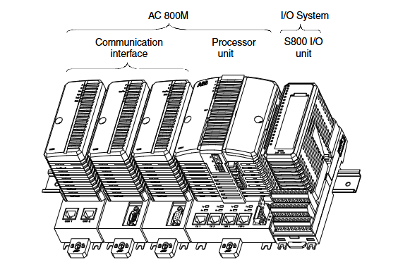
AC 800M Overall: It is a configurable and programmable hardware platform that becomes an AC 800M or AC 800M HI controller after configuration programming, including hardware units such as processor units and high integrity processor units. It can be used as an independent process controller or perform local control tasks in a control network, supporting multiple I/O system connections, requiring firmware loading and application creation using Control Builder M. It is suitable for various applications ranging from small PLCs to advanced DCS. The AC 800M HI controller can run non SIL and SIL classification applications.
Processor unit:
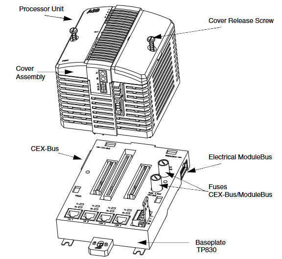
PM8xx/TP830: Composed of a processor unit and a base, the CPU board contains a microprocessor, etc. The power board generates power, and the base has multiple connections. In a single CPU configuration, S800 I/O clusters can be directly connected, and CEX Bus can expand communication ports.
PM891: High performance controller, connected to S800 I/O system through optical Modulus, can run independently or in control network, supports redundant configuration, has multiple interfaces and connectors, including redundant links.
Redundancy: PM861 and other processor units support redundancy, and the controller contains two processor units, one as the main and one as the backup. In case of failure, seamless switching is required, and the system can restore redundancy after replacing the faulty unit. PM86x/TP830 and PM891 each have their own characteristics in redundant configuration.
High integrity: AC 800M can be configured for safety critical applications, with main components such as PM865. PM865 has enhanced internal diagnostics, while SM810 and SM811 each have their own characteristics. The high integrity system’s Module Bus telegram uses the concept of long frames.
Control software: It is the generic name for the functions of a controller, consisting of hardware, firmware, and application program functions, and requires the Control Builder M tool to create applications.
Ethernet address: The TP830 base and PM891 unit of PM8xx (excluding PM891) both have unique Ethernet addresses.
Key features: modularity, easy installation, convenient troubleshooting, protection level, EMC certification, support for multiple I/O and communication protocols, battery backup, CPU redundancy, etc.
Product release history: lists the new content and corresponding user documentation for each version of AC 800M.
Installation
Site planning: Temperature, vibration, cooling, grounding and other site selection and building requirements need to be considered, and there are corresponding specifications for cable laying, power supply and enclosure.
Installation steps: including installing the AC 800M unit onto DIN rails, metal plates, and prefabricated aluminum profiles, as well as installing various processor units in different configurations, CEX Bus related units, various interfaces ModuleBus、 The installation of power supply unit, main circuit breaker unit, voting unit, external battery unit, and I/O unit should also pay attention to the installation in the cabinet and the ventilation installation dimensions.
Configuration
Basic information: Use the Control Builder tool to configure hardware and create applications, with relevant documentation and online help providing information.
Connection and Communication: Introduces the connection methods of Control Builder, the characteristics and connections of control networks, the communication ports and functions of processor units, and the setting methods of controller IP addresses under different configurations.
System configuration: It explains various methods for connecting I/O systems, the composition and connection capabilities of ModulaBus, PROFIBUS DP、PROFINET IO、FOUNDATION Fieldbus HSE、TRIO/Genius Remote I/O、Satt I/O The relevant configurations, as well as the connection method of ABB drive system and the configuration of power system.
Operation
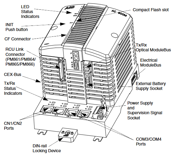
AC 800M Controller (PM8xx): Introduces its composition, functions of LED indicator lights, switches and buttons, as well as the role of connectors.
Startup and Mode: including startup related reference information, redundant configuration startup precautions, operation and characteristics of different startup modes (hot start, cold start, controller reset), and automatic switching to backup CPU.
Operation verification: It explains how to verify the normal operation of AC 800M, including the verification methods for single CPU and redundant CPU.
Maintenance
Preventive maintenance: specifies the frequency and operation of regular system hardware checks, battery replacement, and other preventive maintenance.
Battery replacement: Detailed instructions and precautions for replacing internal batteries, SB821 external battery units, and SB822 rechargeable external battery units.
Online Unit Replacement: Introduces units that can be replaced online and precautions, including CPU replacement under different configurations, online replacement of RCU link cables, etc.
Corrective maintenance: It explains the replacement methods for Module Bus and CEX Bus fuses, as well as the fault finding procedures for various units.
Appendix
Hardware Unit: Provides detailed information on various processor units, CEX Bus interconnect units, SM810 and SM811, various interfaces, power supply units, voting units, modem units, external batteries, DIN rails, and other key features and technical data of devices.
Power consumption: Provides standard fuse requirements for 40 ° C environment, as well as current consumption and power consumption data for various AC 800M units, as well as related calculation methods and maximum current supply information.
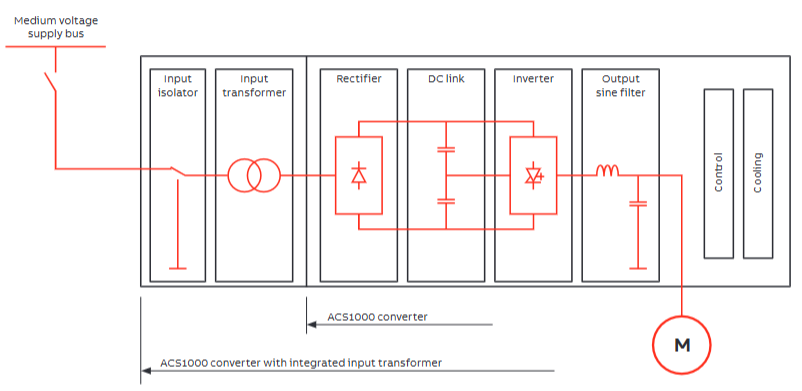
ACS1000 is a medium voltage AC drive solution launched by ABB, designed specifically for controlling medium and high voltage motors. It covers a power range of 1.1-63 MW and is compatible with voltage levels of 2.3-11 kV. Its core advantages include:
Efficient and reliable: Adopting direct torque control (DTC) technology, the dynamic response is fast (speed step response ≤ 10 ms), the speed regulation accuracy is high (± 0.1% rated speed), and the power factor is ≥ 0.95 (at full load), reducing power grid losses.
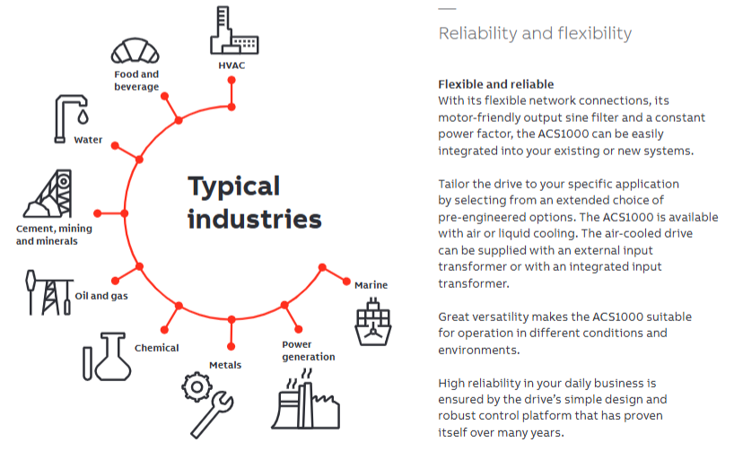
Flexible adaptation: Supports multiple motor types (asynchronous motor, synchronous motor), can be configured as a single drive or multi drive system, and adapts to the load characteristics of different industrial scenarios (such as constant torque, variable torque).
High availability: Modular design supports online maintenance, key components such as power modules and cooling systems can be redundantly configured, with a long mean time between failures (MTBF), reducing the risk of downtime.
Environmental Protection and Compliance: The input current harmonic distortion (THD) is low (≤ 5%), and it can meet international standards without the need
Technical architecture and core components
1. Topological structure
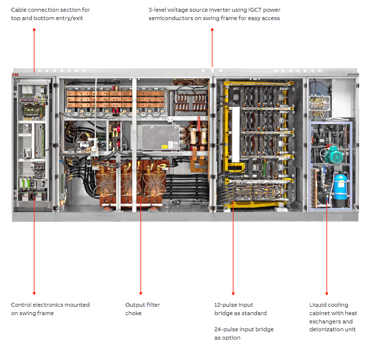
Adopting a three-level NPC (neutral point clamp) inverter design, precise control of voltage and frequency is achieved through IGBT power devices. Compared to traditional two-level topologies, the output harmonics are lower and the motor insulation is friendly.
2. Core components
Power module: including rectifier, inverter, and buffer circuit, divided into different frame sizes according to power level (such as Frame 1-6), supporting parallel expansion.
Control unit: Based on ABB DTC technology, integrated PLC function, supports logic control, sequence control, and PID regulation, and can be operated through Panel Control panel or upper system.
Cooling system: Provides two solutions: air cooling (AC) and water cooling (WC). Water cooling is suitable for high power density scenarios (such as 10 MW or more) and supports connection to heat exchangers or cooling towers.
Auxiliary equipment: optional EMC filters, input isolation transformers, braking units, sine wave filters (to reduce motor harmonic losses), etc.
Model specifications and performance parameters
1. Power and voltage range
Voltage level (kV) Power range (MW) Suitable motor current (A) Typical application scenarios
2.3 1.1-18 300-4500 fans and pumps
3.3 1.5-25 250-4800 Compressor and Conveyor Belt
4.16 2.0-30 300-4200 rolling mill and crusher
6.6 3.0-40 250-3500 Mine Hoist
11 5.0-63 250-3200 Large pump stations, power plant auxiliary equipment
Metallurgy: main drive of rolling mill, coiler, blast furnace fan.
Oil and gas: oil pumps, compressors, and natural gas pipeline pressurization.
Water treatment: large sewage pumps, water supply booster pumps.
Mining: Mine hoist, crusher, scraper conveyor.
2. Typical configuration examples
Standard configuration for fans/pumps: ACS1000 host+air cooling+input isolation transformer+MODBUS communication.
High precision transmission configuration: ACS1000 host+water cooling+encoder feedback+PROFIBUS-DP+sine wave filter.
Service and Support
Full lifecycle services: including installation and commissioning, training, preventive maintenance, remote monitoring (through ABB Ability) ™ Platform, spare parts supply, etc.
Customized solution: Cabinet layout, interface protocols (such as PROFINET, EtherNet/IP), redundant configuration, etc. can be designed according to customer needs.
Positioning: Wall mounted low harmonic AC drive module, used to control AC motors, supports multiple voltage levels (208-690 VAC), suitable for industrial automation scenarios such as fans, pumps, conveyors, etc.
Core advantages:
Adopting direct torque control (DTC) technology, supporting high-precision speed and torque control.
Integrating the input side rectifier and motor side inverter, energy conversion is achieved through IGBT modules, with low input current harmonic distortion (THD).
Support multiple extension functions (such as brake chopper, EMC filter, anti misoperation device), suitable for complex industrial environments.
Technical parameters and specifications
1. Rated performance
Power range: 5.5-110 kW (IEC standard), 7.5-125 HP (NEMA standard).
Voltage and frequency: Supports three-phase 208/230/400/480/690 VAC, frequency 48-63 Hz.
Overload capacity:
Light overload: Allow 10% overload for 1 minute every 5 minutes.
Heavy overload: 50% overload is allowed every 5 minutes for 1 minute.
Efficiency: Approximately 97% at rated power.
2. Structure and Protection
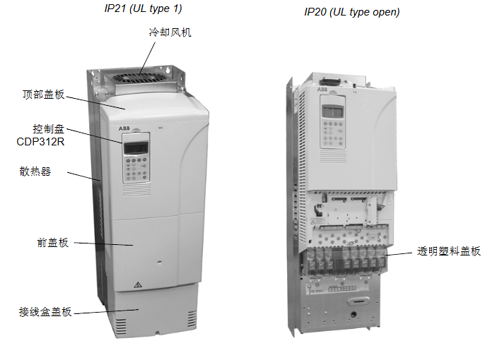
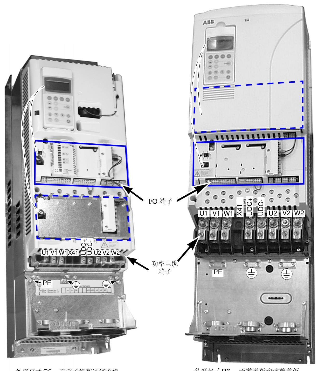
Dimensions: available in R5 (width 265 mm) and R6 (width 300 mm), with protection levels of IP21 (UL Type 1) or IP20 (UL Type Open).
Cooling method: forced air cooling, air flow rate of 350-405 m ³/h, noise level of 70-73 dB.
3、 Hardware composition and interfaces
Core module:
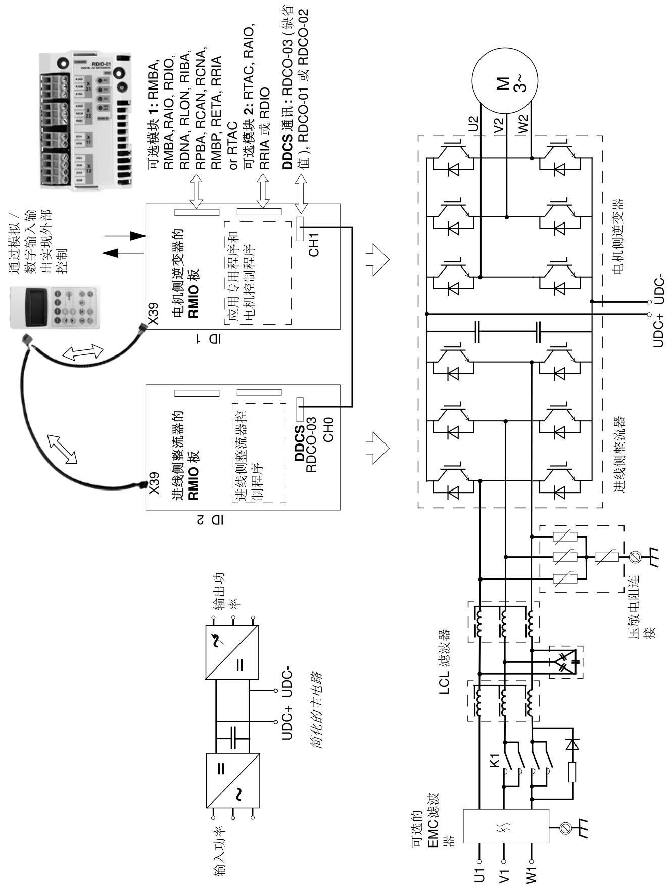
Incoming side rectifier: Rectify AC power into DC power, including EMC filter (optional) to suppress harmonics.
Motor side inverter: Convert DC power into adjustable frequency AC power to drive the motor to operate.
Control board (RMIO): Provides digital/analog I/O, relay output, communication interfaces (such as DDCS fiber optic communication), and supports fieldbus expansion (PROFIBUS, MODBUS, etc.).
Key interfaces:
Power interface: input (U1/V1/W1), output (U2/V2/W2), braking circuit (UDC+/UDC -).
Control interface: Analog input (0-10 V/4-20 mA), digital input (6 channels), relay output (3 channels), control panel interface (CDP312R).
Installation and wiring
1. Mechanical installation
Support wall mounted or cabinet installation, with reserved cooling space (at least 50-200 mm around) to avoid vibration and high temperature environments.
Weight: R5 is about 65 kg, R6 is about 100 kg, and lifting devices are required for handling.
2. Electrical installation
Power cable: Shielded cable is required, with a cross-sectional area selected according to the current (6-185 mm ²), and the shielding layer needs to be grounded 360 ° to reduce electromagnetic interference.
Control cable: For analog signals, it is recommended to use double shielded twisted pair cables, while for digital signals, single shielded cables should be used to avoid parallel wiring with power cables.
Grounding requirements: Strictly follow the PE grounding specifications, and the cross-sectional area of the grounding conductor should not be less than 1/2 of the phase line (or 16 mm ², whichever is larger).
Safety and Maintenance
Safety Notice:
High voltage warning: After power failure, wait for 5 minutes to confirm that the capacitor has discharged completely (voltage<50 V) before operation.
Static protection: When handling printed circuit boards, it is necessary to wear a grounding wristband.
Anti misoperation: An optional AGPS board (+Q950) can be used to block power output through an external switch to prevent accidental startup.
Maintenance cycle:
Cooling radiator cleaning: Every 6-12 months (depending on the amount of dust in the environment).
Cooling fan replacement: Every 6 years (approximately 50000 hours).
Capacitor replacement: Every 10 years (affected by ambient temperature).