Call us 24/7uaedcs@163.com
Welcome to the official website of CNIACS Automation Technology Co., Ltd!
Call us 24/7uaedcs@163.com

Honeywell Sieger System 57 Modbus Interface Module Kit Operating Instructions

Basic information

Product Name: Sieger System 57 Modbus Interface Module Kit

Model: RS422/485 (05701-A-0312), RS232 (05701-A-0313)

Document Number: MAN0502.PM6 Issue 04 October 99 05701M5006

Manufacturer: Honeywell (formerly Zellweger Analytics Limited)

Safety Warning and Precautions

Warn

This device is not designed or certified for use in hazardous areas.

Suitable for indoor use only.

Avoid exposure to rain or moisture.

Precautions

Only use components and accessories approved by the System 57 control system.

To maintain safety standards, qualified personnel must regularly maintain, calibrate, and operate the System 57 control system.

Important Statement

Zellweger Analytics Limited shall not be liable for any failure to install and/or use the equipment in accordance with the corresponding version and revision of this manual.

The user of the manual should ensure that its content is completely consistent with the equipment to be installed and/or operated. If there are any questions, they should contact the company for consultation.

The company reserves the right to modify the information in this document without notifying any individual or organization.

Glossary

A1: Low or warning alarm level.

A2: Second warning alarm level.

A3: High or primary warning level.

LED: Light Emitting Diode.

LTEL: Long term exposure limit (8-hour time weighted average).

RFI: Radio Frequency Interference.

RH: Relative humidity.

STEL: Short term exposure limit (10 minute time weighted average).

TWA: Time weighted average.

Main functions and overview

Function: Provides digital communication between the System 57 control system and external computer systems, supports reading configuration, alarm status, and executing calibration programs.

Compatibility: Compatible with 5701, 5704, and 5704F control cards.

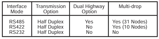
Communication standards: Supports RS485, RS422, and RS232 electrical standards.

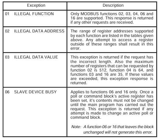
Protocol: Operates as a Modbus RTU and supports the 02, 03, 04, 06, and 16 functions of the Modbus protocol.

Data isolation: The data signal is isolated from the System 57 power supply.

Configuration flexibility: Asynchronous serial links can be configured with baud rate, parity, and stop bits.

Way of working

System 57, as a Modbus Remote Terminal Unit (RTU), only transmits data in response to requests from the master device.

The host system (usually a PLC, DCS, or SCADA graphic package) serves as the main device to control the operation of the communication system.

Installation instructions

Preparation before installation

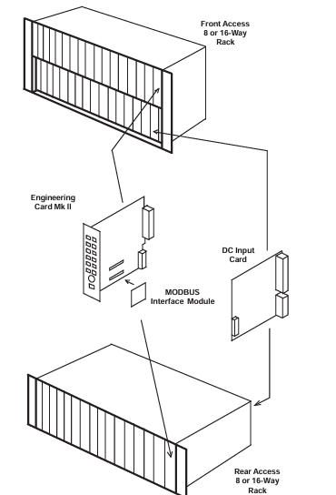
Confirm the type of engineering card, Modbus interface kit can only be installed on Mk 2 engineering cards.

Unpack and inspect the contents of the kit to ensure completeness and no transportation damage.

Installation steps

Cut off all power to the System 57 rack.

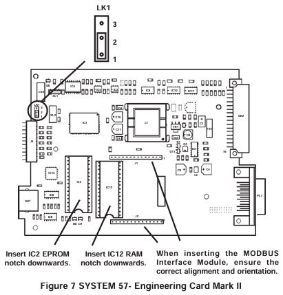
Remove the engineering card, insert the software upgrade EPROM integrated circuit into the IC2 socket of the engineering card, and insert the RAM expansion integrated circuit into the IC12 socket.

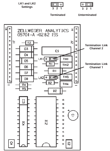
Replace the short-circuit link LK1 of the engineering card.

For RS485/422 modules, set the terminal resistance as needed.

Insert the Modbus interface module into the J1 and J2 sockets of the engineering card and reinstall the engineering card.

On site connection

RS485/422 interface: Connect through the auxiliary terminal block TB2 on the DC input card, use shielded twisted pair cable, pay attention to correctly terminating the transmission line, and avoid signal interference.

RS232 interface: also connected through TB2 of DC input card, using high-quality multi-core shielded cable, following the connection specifications of RS232 standard.

Configure Modbus functionality

Host configuration

It is recommended to configure the host to retry at least twice when communication frames are lost.

System 57 configuration

Communication parameters: configurable modes (RS422, RS485, RS232), baud rate, stop bit, parity check, etc.

Address setting: Each rack needs to specify a unique Modbus master address, and when using RS485 half duplex communication and enabling the secondary bus, a secondary address also needs to be set.

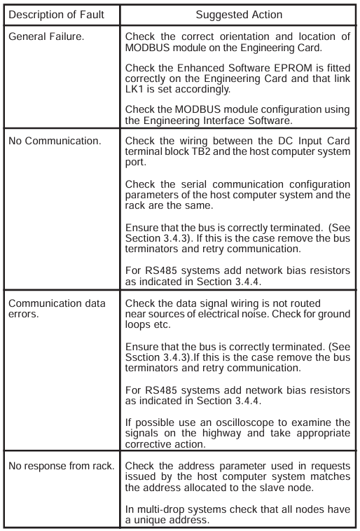
Debugging and Maintenance Instructions

Start program

Ensure that the system power is turned off, reconnect the power, and verify that the LED on the front panel of the engineering card flashes normally and the green POWER ON indicator light remains on.

After the power on suppression time, ensure that the gas detection system operates normally.

Turn on the host system and initiate Modbus master operation.

Simulate alarm conditions, check if the host can correctly detect and take corresponding actions, repeat the test and clear the simulated alarm.

maintenance

The Modbus interface functionality should be regularly tested according to the maintenance procedures in the control system user manual.

Operating instructions

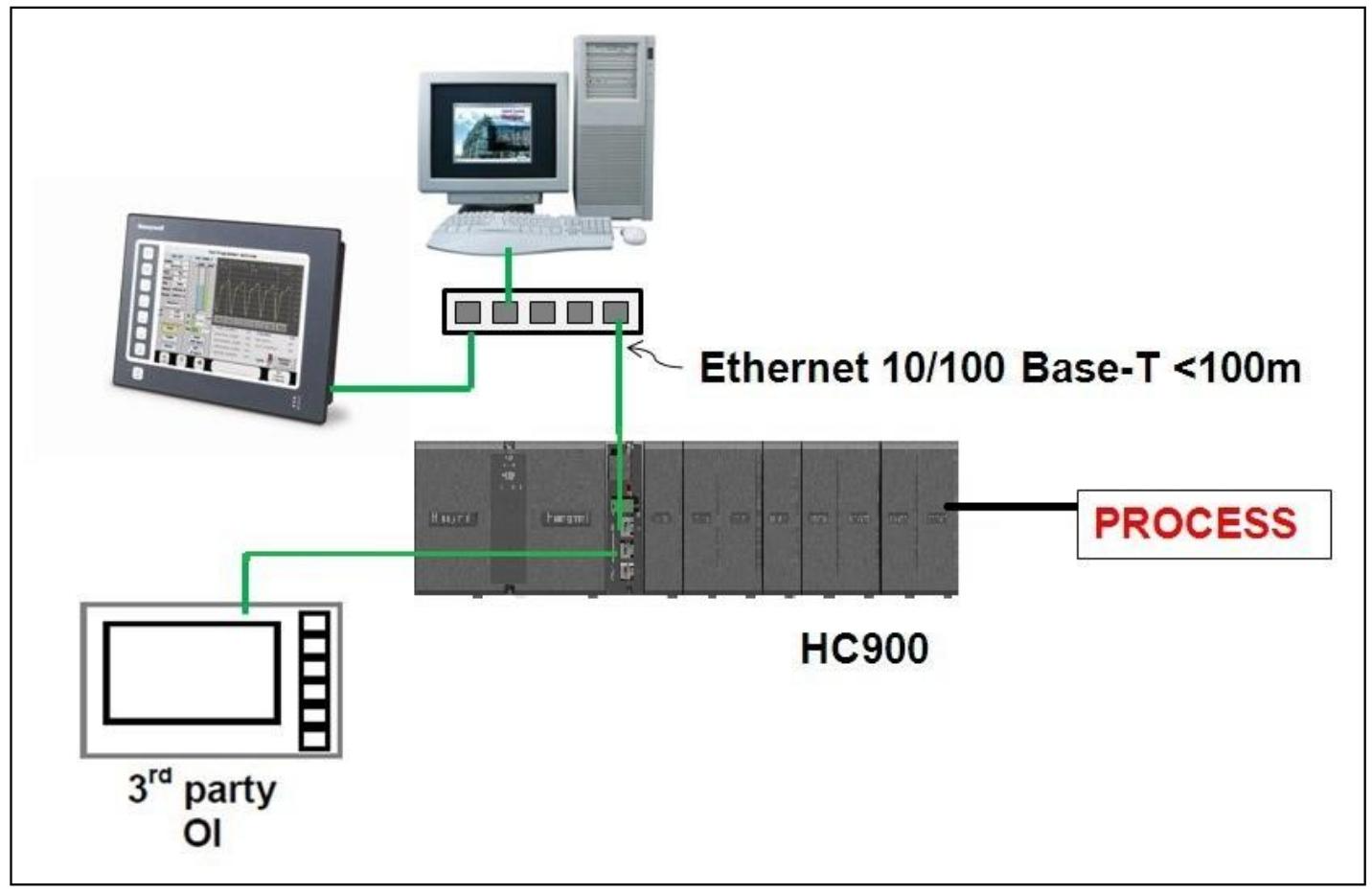
Mainly used to connect gas detection systems to factory control systems, providing centralized monitoring of system status, usually with graphical displays.

The host system needs to be programmed to interpret the signals and status data provided by the System 57 control system.

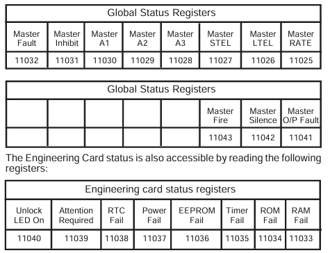
It is recommended that the host system be programmed to use Function 02 to collect alarm and status data from all channels. If the alarm function needs to be reset, Function 06 or 16 should also be implemented.

Modbus Function Reference

Supported Features

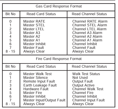
Function 02: Read input status, can read channel status bits, each sub channel has 11 status bits.

Function 03: Read the hold register. The host can read the contents of the hold register and can read up to 35 registers per frame.

Function 04: Read input registers, with two types of input registers: analog signal value and animation value. A maximum of 64 registers can be read per frame.

Function 06: Preset a single hold register.

Function 16: Preset multiple hold registers, up to 35 registers can be set per frame.

Specification parameters

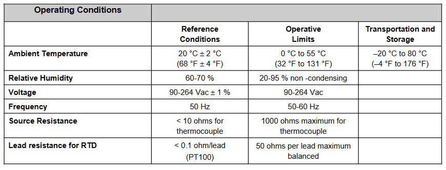
Environmental parameters

Working temperature: -5 ° C to+55 ° C.

Storage temperature: -25 ° C to+55 ° C.

Humidity: 0 to 90% RH (non condensing).

EMC/RFI compliance

Compliant with EN50081 Part 1 and Part 2 (EMC/RFI Generic Emission) and EN50082 Part 1 and Part 2 (EMC/RFI Generic Immunity).

Serial communication

Format: Asynchronous serial data.

Data bit: 8.

Speed: 19200, 9600, 4800, 2400 baud.

Stop position: 1 or 2.

Parity check: odd, even, or none.

Mode: Half duplex.

Modbus protocol

Mode: RTU.

Supported functions: 02, 03, 04, 06, and 16.

RS485/422 interface module

Power supply: Powered by the engineering card.

Power consumption: maximum 1.5W.

Weight: 30g.

On site terminal: 2.5mm ² (14 AWG), located on the DC input card.

Cable type: It is recommended to use shielded twisted pair cables with separate grounding wires.

Input/Output: Two RS485 transceivers (Channel 1, Channel 2).

Working mode: single RS485 highway, dual RS485 highway (primary and secondary) RS422 highway。

Multi node capability: up to 31 nodes (RS485) or up to 10 nodes (RS422).

Maximum cable length: 1200m (3900ft).

Maximum data rate: 19.2k baud.

RS232 module

Power supply: Powered by the engineering card.

Power consumption: Maximum 0.75W.

Weight: 30g.

On site terminal: 2.5mm ² (14 AWG), located on the DC input card.

Cable type: It is recommended to use shielded multi-core wires.

Input/Output: Two data sets (RXD, TXD) and two handshakes (DTR, DSR).

Maximum cable length: 15m (49ft).

Maximum data rate: 9600 bits per second.

Honeywell SK Relay Installation and Maintenance

Product specifications

Normal operating voltage: 15 to 32 VDC

Maximum current consumption: 6.5 mA (when LED lights up)

Average working current: directly polling 230 μ A; Group polling 255 μ A

Terminal Resistance (EOL): Not used

Temperature range: 32 ° F to 120 ° F (0 ° C to 49 ° C)

Humidity: 10% to 93%, non condensing

Size: 4.5 inches high x 4 inches wide x 1.25 inches deep (can be installed on a box measuring 4 inches square and 2.125 inches deep)

Accessories: SMB500 Electrical Box

Product overview

Purpose: Suitable for intelligent two-wire systems, each module’s independent address can be selected through a built-in rotary switch, allowing compatible control panels to switch discrete contacts through code commands.

Structure: Contains two sets of isolated Form-C contacts, used as DPDT switches, with rated values in accordance with the table in the manual; The module does not monitor the circuit connections of relay contacts; The module also has an LED indicator controlled by a panel.

Compatibility requirements

Need to connect to a compatible Silent Knight system control panel (specific list can be obtained from Silent Knight).

Preparation before installation

This information is only for a quick reference installation guide. For detailed system information, please refer to the corresponding Silent Knight control panel installation manual.

To install modules in existing operating systems, operators and local authorities need to be notified that the system will be temporarily suspended.

Disconnect the power supply of the control panel before installing the module.

This manual should be left to the owner/user of this device.

Installation method

SK Relay is directly installed on a 4-inch square electrical box (see Figure 2A), and the minimum depth of the box must be 2 inches.

Silent Knight provides surface mounted electrical boxes (SMB500).

Wiring requirements

All wiring must comply with applicable local codes, regulations, and laws.

When using control modules in non power limiting applications, CB500 module barriers must be used to meet UL’s requirements for power limiting and non power limiting terminal and wiring separation. The barrier must be inserted into a junction box, and the control module must be placed in the barrier and connected to the junction box (Figure 2A). The power limiting wiring must be placed in the isolation quadrant of the module barrier (Figure 2B).

Install module wiring according to the engineering drawings and corresponding wiring diagrams.

Set the address on the module according to the engineering drawing.

Fix the module to the electrical box as shown in Figure 2A (provided by the installer).

Warning message

All relay switch contacts are in standby state (open) at the factory, but may have been switched to active state (closed) during transportation. To ensure that the switch contacts are in the correct state, the module must communicate with the panel before connecting the circuit controlled by the module.

Aerotech EDU176 Ndrive HL series digital servo drive

Product basic information

The manual begins by introducing the basic overview of the Ndrive HL series digital servo drive, including the product’s functional positioning as a high-performance discrete drive option for the Automation 3200 motion system. It can drive various types of motors (brushless motor, brushed DC motor, and stepper motor) and perform current loop and servo loop closure to ensure positioning performance and speed stability. At the same time, basic information such as the version of the manual (Revision: 1.08b), release date (October 31, 2007), and related product number (P/N EDU176) were clarified.

System installation and configuration

This section is an important component of the manual, detailing the specific steps and requirements for product installation and configuration. Including safety operating procedures, emphasizing precautions such as preventing electric shock and mechanical injury that must be followed during installation; The power connection method explains the wiring method, required wire specifications, and related protective measures for the motor power supply and control power supply (- AUXPWR option); Detailed wiring diagrams and phase adjustment methods are provided for different types of motors such as brushed DC motors, brushless motors, and stepper motors, including motor and feedback connections; Encoder feedback connection, introducing the phase adjustment and signal wiring of the encoder; And network configuration related content such as communication channel settings and multi drive connections.

Technical Details Explanation

Deeply analyzed the technical details of the Ndrive HL series products. Covering the pin allocation and functionality of the auxiliary I/O interface (J205), including analog input/output, digital input/output, and secondary encoder channels; Position synchronization output (PSO)/laser triggering function, explaining the working principle, triggering method, supported number of axes, and related parameter configuration of PSO; The pin definition of the motor feedback interface (J207) involves encoder signals, Hall effect signals, limit switch signals, etc; Communication protocol and pin allocation between RS-232/RS-422 ports and FireWire bus; It also includes parameter settings, hardware configuration, and fault handling for voltage current mode operation.

Optional Features and Accessories

Introduced the optional options and related accessories of the product. The optional options include – IOPSO and – IOPSOH expansion boards, – DUALPSO and – TRIPLEPSO laser triggering options, – ENET (Ethernet) options, – RDP rotary transformer input options, etc. The functions, hardware composition, and configuration methods of each option are described in detail. The attachment section lists the models, descriptions, and applicable scenarios of standard interconnect cables, as well as the connection methods for joystick and handwheel interfaces.

Troubleshooting and Maintenance

Provided diagnosis and solutions for common faults, listed in table form the possible causes and countermeasures for faults such as motor loss of control, amplifier alarm, overcurrent, overtemperature, etc; Introduced the testing points, jumper settings, and fuse information for key components such as the control board, motor power board, and power supply board; Explained the meaning of LED indicator lights, helping users determine the operating status of the device through the status of the indicator lights; It also includes recommendations for preventive maintenance, such as regularly checking cable connections, cleaning equipment, etc.

Aerotech Ndrive HP 10/20/30 Series Digital Servo Drive

Product Overview

Functional Features

Suitable for brushless motors, brushed DC motors, and stepper motors, supporting full digital control of current loop, speed loop, and position loop, with a sampling rate of up to 20kHz.

Equipped with flexible redundancy design, supporting simplex, duplex, and triple module redundancy (TMR) systems, different levels of redundancy can be selected according to application requirements.

Provide rich I/O interfaces, including analog input/output, digital input/output, encoder feedback interface, etc., supporting high-speed user input (with a delay of about 50 nanoseconds).

Supports Position Synchronized Output (PSO)/laser triggering function, with a single axis triggering delay of 200 nanoseconds and a dual/three-axis triggering delay of 275 nanoseconds, enabling high-precision synchronous control.

Adopting IEEE-1394 (FireWire) ®) Communication bus, with a data transmission rate of 400Mbps, supports multi drive networking control, and can connect up to 32 axes.

Model and specifications

It includes three models: Ndrive HP10, HP20, and HP30, with peak output currents of 10A, 20A, and 30A respectively, and continuous output currents of 5A, 10A, and 15A respectively.

The power input supports single-phase or three-phase AC, with a voltage range of 85-240VAC, a frequency of 50/60Hz, and a bus voltage range of 100-320VDC (optional 40-80VDC).

The working environment temperature is 0-50 ° C, the storage temperature is -20-70 ° C, the humidity is 5-95% (non condensing), and the highest altitude is 2000 meters.

Installation and Configuration

Safety regulations: Emphasize electrical safety during installation, including precautions such as power-off operation, electric shock prevention, and mechanical injury prevention. Use cables and connectors that meet specifications.

Wiring and Grounding: Provide detailed instructions on the methods of power wiring (main power supply, control power supply), motor wiring, and feedback wiring (encoder, Hall sensor, etc.), emphasizing shielding and grounding techniques to reduce electromagnetic interference (EMI).

Motor configuration: Supports wiring and phase adjustment for brushed DC motors (torque mode, with speed feedback), brushless motors (Hall effect feedback, encoder feedback), and stepper motors, providing steps and methods for determining motor phase.

Communication settings: Set the communication channel number (1-32) of the drive through switch S2, supporting Daisy Chain or star topology of FireWire bus, and can connect up to 16 drives.

Technical Details

Auxiliary I/O interface (J205): Provides 4 optical isolated outputs, 6 optical isolated inputs (including 2 high-speed inputs), analog input/output, secondary encoder channels, supports RS-422 differential signals, and can be used for master-slave control or dual feedback systems.

Position Synchronization Output (PSO): Supports single axis, dual axis, and three-axis laser triggering, and can generate synchronization pulses based on encoder signals, external triggers, or software instructions. It has high triggering accuracy and is suitable for high-precision synchronization applications such as laser processing.

Motor feedback interface (J207): Supports differential line driven encoder, Hall effect sensor, limit switch, motor overheat thermistor input, encoder supports up to 8MHz signal (32MHz after fourth harmonic).

Communication interfaces: including RS-232/RS-422 (for firmware upgrade), FireWire (main communication bus), optional Ethernet interface (- ENET option), supporting ModBus TCP protocol.

Voltage current mode: supports independent operation mode, controls motor current through analog input (± 10V), suitable for use with external controllers, requires configuration of relevant parameters and saving to flash memory.

Optional Features

-IOPSO and – IOPSOH Options Board: Extended I/O interfaces, including 8 optically isolated inputs/outputs, 2 18 bit analog outputs, 2 16 bit differential analog inputs, SSI network interfaces, absolute encoder interfaces, and brake relays. – IOPSOH supports higher output currents (1A/channel).

-DUALPSO and TRIPLEPSO options: Supports dual axis/three-axis laser triggering, requiring the transmission of encoder signals from other axes through SSI network or auxiliary encoder channels, with a maximum tracking rate of 5MHz.

-ENET option: Provides 10/100BASE-T Ethernet ports, supports ModBus TCP protocol, and is used to connect third-party I/O modules.

-RDP Rotary Transformer Input Options: Supports 1-2 ways of rotary transformer or induction synchronizer input, with optional carrier frequencies of 10kHz, 7.5kHz, and 5kHz. Phase and gain parameters need to be configured.

-MXH option: Encoder resolution multiplier, supporting up to x2048 multiplication (up to x8192 when combined with fourth harmonic), suitable for high-precision positioning, with a maximum input frequency of 200kHz.

Accessories and Troubleshooting

Standard cables: Provide models and specifications of motor cables, feedback cables, SSI network cables, etc., supporting different lengths and connector types.

Interface between joystick and handwheel: Instructions on how to connect single/dual axis joystick and handwheel for manual positioning, requiring calibration of analog input range.

Troubleshooting: List the causes and solutions of common faults (such as motor loss of control, driver alarm, overcurrent, overheating, etc.), provide information on the meaning of LED indicator lights, test point locations, fuse replacement, etc.

Preventive maintenance: It is recommended to check cable connections, cooling and ventilation, clean equipment every month to prevent liquids and conductive substances from entering the drive and ensure the normal operation of the equipment.

Aerotech Ndrive series digital servo drives

Series Overview

The Ndrive series digital servo drive is a high-performance discrete drive option for the Automation 3200 motion system, featuring the following features:

Driving capability: It can drive brushless motors, brushed DC motors, and stepper motors, execute current loop and servo loop closure, and ensure high-level positioning performance and speed stability.

Processing capability: Equipped with a high-performance digital signal processor (DSP), it can perform complex calculations in real-time. The sampling rate of the digital current loop and servo loop can reach 20kHz, and it can also handle digital and analog I/O, laser triggering, and encoder multiplication.

Network and Expansion: Some models (such as HP and HL) have optional dedicated Ethernet ports that can communicate with I/O modules from third-party vendors; Support on FireWire ®  Combine usage online and customize the system as needed.

General options: including onboard encoder multiplier, three-axis position synchronous output (PSO), brake relay, additional I/O, absolute encoder interface, and independent logic power input for “keep alive” operation.

Power input: HP, HL, CP, and CL models accept AC input power, while MP models accept DC input power.

Special model: HL is a linear power amplifier suitable for low noise and ultra-high performance applications, meeting high bandwidth requirements, with excellent linearity and no cross distortion; CP is a high-performance PWM amplifier designed for cost sensitive applications; CL is a high-performance linear amplifier designed for cost sensitive applications, while CP and CL retain complex control architectures but eliminate support for optional features; MP is the smallest amplifier in the series, suitable for applications with ultra compact space requirements.

Comparison of Parameters for Various Models

Model Current Output (Peak/Continuous) Power Input Amplifier Type Motor Type Basic I/O Additional I/O (Beyond Basic I/O) Multi axis PSO Supports Third Party I/O Ethernet Capability “Keep Active” Function

Ndrive HP 10-150A/5-75A 2 or 3-phase AC PWM with brushed, brushless, stepper 4-channel digital output/6-channel digital input, 1-channel analog output/1-channel analog input, 8-channel digital output/8-channel digital input, 1-channel analog output/1-channel analog input supports single axis, dual axis, and three-axis

Ndrive HL 10-20A/5-10A 2-phase AC linear brushed, brushless, stepper 4-channel digital output/6-channel digital input, 1-channel analog output/1-channel analog input, 8-channel digital output/8-channel digital input, 1-channel analog output/1-channel analog input supports single axis, dual axis, and three-axis

Ndrive CP 10-30A/5-15A 2-phase AC PWM with brushed, brushless, and stepper 4-channel digital output/6-channel digital input, 1-channel analog output/1-channel analog input 16 channel digital output/16 channel digital input, 1-channel analog output/1-channel analog input only supports single axis absence

Ndrive CL 10A/5A 2-phase AC linear brushed, brushless, stepper 4-channel digital output/6-channel digital input, 1-channel analog output/1-channel analog input 16 channel digital output/16 channel digital input, 1-channel analog output/1-channel analog input only supports single axis none

Ndrive MP 10A/5A DC PWM with brushed, brushless, and stepper (no clear basic I/O data) 8-way digital output/8-way digital input, 1-way analog output/1-way analog input only supports single axis without any input

Detailed specifications for each model

Ndrive HP: Output voltage 100-320VDC, PWM switching frequency 20kHz, operating temperature 0-50 ° C, supports 1-3 phase AC input (50-60Hz, 115-240VAC), encoder input frequency can reach 200kHz (with onboard multiplier) or 40MHz LTT square wave, current loop and servo loop update rates are 20kHz and 1-20kHz respectively, options include “keep active”/auxiliary power supply, brake output, position synchronization output, etc. Different sub models have differences in peak and continuous current, weight and other parameters.

Ndrive HL: Output voltage ± 40VDC or ± 80VDC, operating temperature 0-50 ° C, storage temperature -30-85 ° C, supports single-phase AC input (50-60Hz, 115-240VAC), encoder input frequency and other parameters are similar to HP, and optional options include “keep active”/logic power input, brake output, etc. The parameters vary among different sub models.

Ndrive CP, CL, and MP: The working temperature of CP and CL ranges from 0-50 ° C, with CP output voltage of 100-320VDC, CL output voltage of ± 40VDC, and MP output voltage of 10-80VDC. The input power supply, encoder input frequency, update rate, and other parameters vary, and the available options also vary depending on the model.

Components and Dimensions

Each model has its own specific component configuration, such as the HP series including FireWire interface, Resolver interface (optional), power supply, and other components; The HL, CP, CL, and MP series also have corresponding components. At the same time, the document also provides detailed size parameters (including millimeters and inches) for each model and different configurations.

ZYGO ZMI 2000 System

Displacement Measuring Interferometry improves positioning accuracy.  Zygo’s ZMI 2000 is the industry’s top performing Displacement Measuring Interferometer (DMI) System offering the highest resolution, the highest velocity, and lowest data age uncertainty for real time position control.  Zygo, a world-class interfero metric metrology company, supports you at all levels of design, engineering and manufacturing.  Zygo works as an extension of your research, engineering and  manufacturing teams in providing metrology solutions.

Performance Benefits of the ZMI 2000

• Positioning accuracy – Velocity and time dependent errors are eliminated.  All axes of motion are synchronized to an uncertainty of ≤1.7 ns.

•Overlay accuracy – λ/2048 resolution(0.31 nm) with 2 pass interferometers for excellent overlay and alignment capability.

• System throughput – Slew rates of 2.1 m/s with 2 pass interferometers enabled by the 20

MHz heterodyne split frequency

ZMI 2000 Systems are found in the most demanding feedback control applications:

• Lithography tools: optical steppers and scanners,e-beam and laser mask writers.

•Mask, wafer and LCD inspection and measurement tools, CD-SEM’s.

• Process equipment, memory repair tools.

Integration Benefits of the ZMI 2000 for real-time position control

•Reduce heat, cost and ESD sensitivity, improved electrical isolation, and minimal package size

Fiber optic cables are used on both the reference and measurement legs.

•Reduce cost in backplane space requirements

The ZMI 2002 offers two axes of interferometry on a single 6U VME board.

•Reduced design costs with simplified integration time – The measurement boards are fully programmable through the interface bus (VME or ISA), or the P2 interface.

•Reduced cost of integration – Standard hardware interfaces for up to 7.7 MHz P2 data rates for up to 16 axes.  Easily expanded to accommodate more axes at the same rates.

The ZMI 2000 as a Metrology System Unparalleled performance and flexibility.  All of the performance benefits of the ZMI 2000 with the following integration options:

• ZMI Systems Chassis with PCI-VME for processor speed real-time data,

• ZMI Systems Chassis with serial or GPIB interface for more cost effective solutions,

• ZMI PC for integration into an ISA slot.

ZMI 2000 Systems are in use in Standards Labs worldwide for applications in measurement and calibration of high resolution and high frequency mechanical motions:

• Piezo transducer calibration,

• Linear Scale calibration,

• Rotary Scale calibration,

• AFM stage calibration.

The ZMI 2000 System Laser Head

The laser source may be the single most critical component of the Displacement Measuring Interferometer.  To control and assure laser head quality, Zygo manufactures our own laser tubes.

The proprietary tube design, combined with a state-of-the-art assembly and test facility, provides for a highly reliable laser head with:

• > 50,000 hour lifetime,

• Longest basic warranty at 18 months,

• Extended warranties of up to 5 years,

• Up to 8 axes of interferometry on a single head,

• Multiple head synchronization.

ZMI 2000 System Integration Features

• Optical power monitor for the laser head output,

and measurement board input.

• Built in laser head diagnostics.

• Position, time, and velocity, all available independently on the P2, or VMEbus.

• Programmable synchronization signal.

• Measurement boards can be used in any standard 6U VME or ISA backplane.

The ZMI 2000 System technology combined with our world-class opto-mechanical design and manufacturing center in Middlefield, CT makes Zygo Corporation a key partner in the successful design, manufacture, and integration of your real-time position control systems.

GE Mark VIe Control System

Introduction

The Mark VIe control system is a flexible platform suitable for various application scenarios, with high-speed networked input/output (I/O) functionality, supporting simplex, dual, and triple redundant systems. It adopts industry standard Ethernet communication for connecting I/O, controllers, operators and maintenance stations, as well as third-party systems. The ControlST software suite (including the ToolboxST toolset) is used for programming, configuration, trend analysis, and diagnostics of the system, providing high-quality, time consistent data at the controller and factory levels to assist in effective management of control system equipment. In addition, the Mark VIeS safety control is an independent safety control system suitable for safety critical applications that comply with the IEC 61508 standard. It also uses the ControlST software suite to simplify maintenance, but has unique certified hardware and software modules.

System Overview

Core components: With a single board controller as the core, it includes a main processor, redundant Ethernet drivers for communicating with networked I/O, and additional Ethernet drivers for controlling the network. The main processor and I/O modules adopt a real-time multitasking operating system, and the control software is stored in non-volatile memory in a configurable control block language. It also supports IEEE 854 32-bit floating-point format and Sequential Function Chart (SFC).

I/O Network (IONet): It is a dedicated full duplex point-to-point protocol that provides a deterministic high-speed 100MB communication network, suitable for local or distributed I/O devices, supports single, dual, and triple redundancy configurations, and also supports copper and fiber optic interfaces.

I/O module: It consists of three parts: terminal board, terminal block, and I/O package. There are two types of terminal boards: T-type and S-type. T-type usually assigns inputs to three independent I/O packs, while S-type provides a set of screws for each I/O point. The I/O packet contains two Ethernet ports, a power supply, a local processor, and a data acquisition board, which can be added according to application requirements to expand I/O capabilities. It supports simplex, dual, or triple redundant configurations.

Redundant configuration: Provides multiple redundancy options for processes with different levels of criticality, involving multiple control components such as power supply, power supply, I/O pack, Ethernet port, IONet, and control network. The dual redundant system transmits inputs to dual controllers through dual IONets, while the triple redundant system processes faulty components through 2-out-of-3 logic selection or median selection.

Temperature rating: The operating temperature range of electronic devices such as controllers, I/O modules, and power supplies is -30 to 65 ° C (-22 to 149 ° F), with some fieldbus solution modules having slightly reduced operating temperature ranges. During transportation and storage, the temperature range for controllers and other equipment is -40 to 85 ° C (-40 to 185 ° F), while for control room equipment it is 0 to 30 ° C (32 to 86 ° F).

Controller: Compact and flexible design, with multiple frame rate options, different processor speeds, multiple Ethernet, USB, and COM ports, supports simplex, dual, and triple configurations, power supply of 18 to 32V DC, no battery, with status LED, specific cooling method, in compliance with IEC-61508 safety standards, Achilles Level 1 safety certification, operating temperature varies by model, humidity is 5 to 95% non condensing.

Network Security: As a global leader in automation and control, GE regards network security management as an inherent feature of the Mark VIe control series, including network security enhanced control system components, top-notch security features, and software patch services. Security measures include security configuration, secure network architecture (three-layer protection), role-based access control, enhanced control systems, etc. Both controllers and HMI operations have corresponding security protection mechanisms, as well as functions such as security information and event management (SIEM), antivirus patch management, and security patch services.

​ControlST software suite

Composition: Includes WorkstationST HMI and history management application, ToolboxST configuration and diagnostic application, and CIMPLICITY graphical tool, suitable for various control applications of GE.

Human Machine Interface (HMI): A Windows based operator station and engineering workstation that can be used as an independent operator station, engineering workstation only, or both, with options for commercial and industrial grade computers. Communication is carried out through Ethernet control networks and separate Ethernet information networks, supporting redundant HMIs and Ethernet networks to improve reliability. Key control and protection functions are processed in the controller, which also performs high-precision time stamping and maintains alarm status.

WorkstationST HMI and Historical Recording Software: Provides a foundation for operator experience, integrates graphical tools, and can manage control system functions such as alarms, events, logs, historical data, networks, and web interfaces. It has functions such as alarm server and viewer, multiple OPC servers, internal and external history recording interfaces, HMI configuration, device manager gateway, Modbus communication, network time protocol (NTP), and user role security system.

ToolboxST Configuration and Diagnostic Application: Provides a universal configuration tool for hardware and software from I/O modules, controllers to operator stations, simplifying system configuration and enhancing troubleshooting capabilities through advanced diagnostic tools. It has key functions such as software editor, trend analysis, block chart, specific application block library, configuration management system, hardware and software configuration, diagnostic display and message, and search tool.

GE Multilin MLJ synchronous inspection relay

Product Description and Application

Main applications: including connecting the generator to the system, re establishing the connection between two parts of the system, manually closing circuit breakers, automatic reclosing of circuit breakers after relay tripping, etc.

Function: As a digital synchronous check relay, it can measure bus and line voltage, test voltage difference, frequency slip, and phase angle between two voltages. When all values are within the set range and maintained for a set time, it provides output to allow the circuit breaker to close; If the conditions are not met, a closed condition failure signal will be issued one minute later.

Operation mode: divided into continuous mode (continuous check synchronization) and manual mode (starting synchronization control when voltage is applied through manually activated input).

Other features: Equipped with two undervoltage units to control synchronization function, allowing synchronous operation only when both voltages are higher than the set value; It also has DLDB (Dead Line Dead Bus), DLLB (Dead Line Active Bus), and LLDB (Active Line Dead Bus) functions, which can be independently set to select any combination.

Design Features and Application Scenarios

Measurement accuracy: Differential angle measurement has high accuracy, limited only by the error of available voltage transformers, and the measurement is almost independent of voltage. High accuracy is achieved by numerical calculation of digital voltage samples, rated as 2 °, which is superior to other technologies.

Harmonic influence: Based on discrete Fourier transform for measurement and calculation, it is essentially a harmonic filter. Voltage and line measurements are not affected by frequencies other than the fundamental wave, and have the ability to resist harmonics in frequency measurements.

Voltage limitation: When the voltage is below 9 volts, the relay stops measuring phase and frequency and is not allowed to close.

Time parameter: The minimum closing time is set to 100ms, but it is actually 160ms; there is a fixed allowable signal maintenance time of about 130ms.

Synchronization conditions: including the amplitude difference, angle difference, and frequency slip between two voltage signals, all of which must meet the set conditions.

Application scenario: Suitable for situations where two parts of the system are connected through circuit breakers and interconnected at other points in the system. Different scenarios have different requirements for measuring time and frequency slip settings.

Operating principle

Configuration unit: Parameters such as frequency (50 or 60Hz), unit number, communication speed, etc. can be selected and changed.

Synchronization check unit: Analyze the voltage amplitude, input status, and settings on both sides of the circuit breaker, and provide synchronization signals when conditions are met. There are two operating modes, manual and continuous, based on the manual input status, with corresponding time delay mechanisms and setting parameters.

Undervoltage unit: an independent unit with multiple undervoltage and overvoltage functions, which allows the circuit breaker to be closed in dead wire and/or busbar situations. It can operate under different undervoltage conditions (DLDB, DLLB, LLDB) without time delay through settings.

Input unit: Three digital inputs are activated by DC voltage. The input unit reads the input status and filters out possible bounce or noise. Different inputs have different functions, such as indicating the status of the circuit breaker with the input of 52 B, and changing the delay time of the synchronization unit with the input of manual mode.

Self checking unit: The relay continuously performs internal checks during operation to verify the integrity of components, including program memory, working memory, etc. When a fault is detected, it is indicated on the display screen through code, generating an alarm signal and disabling the output.

Output unit: There are 5 outputs, which are relay contacts that can be configured as normally open or normally closed through internal jumpers. They receive signals from the synchronization, undervoltage, and self-test units and activate the corresponding relays according to the configuration.

Power supply: Generate internal voltage required for relay operation from auxiliary voltage, isolate internal circuits from external interference, and be a wide range switch mode power supply.

Technical characteristics

Model List: Define MLJ models through different code combinations, involving communication methods, auxiliary and input voltages, casings, etc.

Technical parameters: including frequency, rated voltage, auxiliary power supply, maximum allowable voltage, temperature range, environmental humidity, and the breaking capacity of each contact.

Insulation: Complies with IEC 255-5 standard, with specified insulation voltage and testing time between each terminal and ground, as well as between independent circuits.

Type test: Multiple tests including 1MHz noise test, impact test, and electrostatic discharge test were conducted, which comply with relevant standards.

Honeywell ControlEdge HC900 Controller 

Overview

The ControlEdge HC900 controller is an advanced circuit and logic controller with a modular design that can meet the control and data management needs of various process equipment. Highly integrated with the optional 900 Control Station operator interface, it minimizes configuration and setup time, combined with Honeywell’s proven control technology, providing an ideal solution for process control. Open Ethernet connection supporting Modbus TCP protocol, allowing network access using multiple HMI/SCADA software, and program execution environment protected by independent watchdog timers.

Application Fields

Widely used in industries such as mining and metals, chemical, pharmaceutical, railway/infrastructure, HVAC/data centers, pulp and paper, cement and glass, electricity, etc. Specific equipment includes furnaces, kilns, boilers, extruders, high-pressure sterilizers, sterilizers, dryers, combustion management, combustion control, emergency shutdown systems, pipeline monitoring, leak prevention systems, etc.

Functional Features

Redundancy support: Supports separate rack redundancy, redundant and non redundant architectures for secure universal I/O, controller redundancy, etc.

Communication function: Supports HART IP protocol and can communicate with Honeywell FDM (Field Device Manager); Support HART function block; Supports Modbus TCP protocol for Ethernet communication, enabling peer-to-peer communication; Support email alerts/event messages, etc.

Control function: Equipped with advanced PID loop control and Accutune III automatic tuning function; Support multiple control algorithms and logic function blocks; Support sequence event recording (SOE), etc.

Configuration and programming: Use Windows based Designer software for configuration, supporting multiple languages; Process configuration changes can be made in operating mode while maintaining process control; Provide rich reporting functions, etc.

Storage and Memory: Adjustable square pool memory, which can be allocated for recipes, set point curves, sequences, and scheduling; Use flash memory to store user configuration programs, battery backup memory for dynamic data storage, etc.

Other functions: Supports hot plugging of I/O modules; Equipped with LED indicator lights to display digital I/O status; Support configuration of graphic function blocks; Equipped with extended alarm and event monitoring functions.

Architecture

Non redundant architecture: including single process/single rack (process), single process/single rack (safety), single process/multi remote rack (safety), multi process/multi rack (process), multi process/multi rack (redundant network star topology), multi process/multi rack (redundant network ring topology), etc.

Redundant architecture: Two redundant C75 CPUs run in separate controller racks, each with an independent power supply. The redundant switching module (RSM) is located in the rack between the two C75 CPUs, and the CPUs communicate with up to 12 I/O racks through 100base-T Ethernet physical communication links or optical fibers with external media converters.

CPU module

Models: including C30 and C50 (non redundant applications), C70 (dual network), C75 (redundant CPU applications and dual network).

Architecture and Memory: Based on the e300 32-bit RISC architecture, PowerPC, C30, and C50 modules use 64MB DDR2 memory, while C70 and C75 modules use 128MB DDR2 memory. All modules’ DDR2 memory supports ECC circuits, enhancing reliability and error detection capabilities.

Communication: All CPU modules provide open Ethernet communication, and C70 and C75 offer dual Ethernet ports for high network availability installations.

Scanning method: Adopting a dual scanning method to process fast digital scanning and normal analog input scanning in the same integrated control environment.

I/O modules and scanners

I/O module types: including various analog input modules, analog output modules, digital input modules, digital output modules, pulse/frequency/orthogonal I/O modules, etc., with different points and isolation characteristics.

I/O scanner: Remote I/O is processed through the remote I/O scanner module and communicates with the main CPU module. There are single port models (for non redundant CPU systems) and dual port models (for redundant CPU systems).

Hot swappable: Supports removing and inserting I/O modules while powered on for easy maintenance.

Terminal block: Provides 20 screw terminal blocks with barrier or Euro style screw connections. Some high-capacity modules require 36 screw Euro style terminal blocks.

Honeywell UDC1200&UDC1700 Universal Digital Controller Series

Overview

UDC1200 and UDC1700 are 1/16 DIN and 1/8 DIN controllers, respectively, based on microprocessors, with high functionality, reliability, and low cost. They are dedicated to monitoring and controlling temperature, pressure, and liquid level, and are widely used in environmental testing chambers, furnaces, ovens, packaging machines, as well as industries such as plastics, food, and beverages. It is equipped with large and easy to read dual 4-digit displays and tactile buttons, making it convenient to configure and use. It has high flexibility and can be configured for different applications, and is compatible with UDC1000/1500 downwards.

Characteristics

Dual Display Screen: Two 4-digit 7-segment LED displays, configurable to display PV and SP (non adjustable), PV and SP (adjustable), PV and slope SP, PV only, and other content.

Easy to configure: Two configuration levels (configuration mode and setup mode) facilitate access to parameters, and a 4-digit security code prevents unauthorized changes.

Moisture resistant front: Complies with NEMA 3/IP65 front protection standards and is dustproof and waterproof.

Universal input: can accept seven different types of thermocouples RTD、 Linear input of current and voltage, all inputs can be configured as standard.

Universal power supply: can operate at any line voltage from 90 Vac to 264 Vac, 50/60 Hz, and also offers 24/48 Vac/dc model options.

Easy upgrade: All option boards do not require jumpers, and the instrument can automatically detect them.

Convenient output selection: All outputs of the instrument (including control outputs) can be changed to meet the exact needs of customers.

Alarm strategy: Two soft alarms for PV, including deviation high/low/absolute alarms, as well as special circuit alarms that can suppress alarms during power start-up and setpoint switching.

Manual/Automatic Mode: Manual control (disturbance free switching) can be enabled through the front AUTO/MAN button.

Pre tuning and self-tuning strategies: Pre tuning is used to set PID parameters close to optimal values, while self-tuning algorithms are subsequently used to optimize tuning parameters.

Limit Controller: The UDC1200 limit controller is packaged in 1/16 DIN and designed to provide safe shutdown and optional alarms.

Up to three outputs: can provide up to three outputs for time and current ratio, duplex mode (heating/cooling), PV or SP retransmission, and alarm.

Setpoint Slope: The current setpoint can be sloped to a new target setpoint at a user-defined slope rate.

Dual Setpoints: UDC1200 and UDC1700 offer dual setpoint options, selecting the current setpoint through numerical input.

Communication function: RS485 communication interface is optional, which can connect up to 32 units and one host at up to 19200 baud rate through ASCII or Modbus RTU protocol.

High security: Non volatile memory based on EEPROM technology ensures data integrity in the event of power failure, with a retention time of over 100 years, and a 4-digit security code to prevent unauthorized or accidental changes.

Optional Features

RS485 ASCII communication, RS485 Modbus RTU communication, digital input, output 2, output 3, 24/48 Vac/dc power supply and other functions can be selected through the model selection guide.

Physical description

UDC1200: The shell depth is 110 mm (4.33 inches), with a standard UDC gray border, and can be installed at 1/16 DIN panel cutouts.

UDC1700: The shell depth is 100 mm (3.94 inches) and can be installed at the 1/8 DIN panel cut. It can be easily and safely installed to the panel cut using the accompanying pre assembled installation fixture. The modular plug-in structure is easy to access, and all inputs and outputs are connected to the rear terminal block by screws.

Operator interface

Provide four display combinations, the upper 4-digit 7-segment display is always used to monitor PV, and the lower display can display set points (read-only), set points (adjustable), slope set points (slope mode), blank, and other content. There is an AUTO/MAN button on the front (to select manual or automatic mode, which changes to “reset” on UDC1200 limit models)

Search for products

Back to Top
Product has been added to your cart