Call us 24/7uaedcs@163.com
Welcome to the official website of CNIACS Automation Technology Co., Ltd!
Call us 24/7uaedcs@163.com

Honeywell Spyder® BACnet® Programmable Controllers

APPLICATION

The PUB and PVB controllers are part of the Spyder family. The nine controllers are BACnet MS/TP network devices designed to control HVAC equipment. These controllers provide many options and advanced system features that allow state-of-the-art commercial building control. Each controller is programmable and configurable using the NIAGARA FRAMEWORK® software.

The Spyder BACnet controllers require the Spyder BACnet Programmable Feature to be licensed in the WEBpro workbench tool and the WEBS AX JACE Controller for programming and downloading. The Spyder BACnet Models are also available as Individually Licensed Controllers (ILC). The ILC versions are identical in design and capability in every detail except for the licensing. The Individual Licensing of the Spyder ILCs (the License is built in) allows them to be programmed and downloaded with any brand of the Niagara Workbench or JACE controller. The Spyder ILCs are identified with a suffix on the Part Number of -ILC. Example: PUB6438S-ILC follows all the same Installation Instructions information as the PUB6438S.

The controllers are for use in VAV (Variable Air Volume), Unitary, and advanced HVAC control applications. Each controller contains a host microcontroller to run the main HVAC application and a second microcontroller for BACnet MS/TP network communications. Each controller provides flexible, universal inputs for external sensors, digital inputs, and a combination of analog outputs and digital outputs.

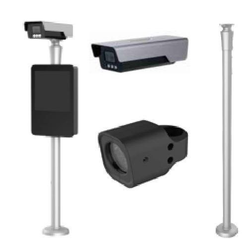
The photo shown is the PVB6436AS, which includes the Series 60 floating actuator.

FEATURES

• Uses BACnet MS/TP network communication.

• EIA-485 communications network. Capable of baud rates between 9.6 and 115.2 kbits/s.

• Capable of stand-alone operation, but can also use BACnet MS/TP network communications.

• Sylk™ bus for use with Sylk-enabled sensors.

• Support for up to 40 controllers per BACnet MS/TP segment (under 30 is recommended).

• Field configurable and programmable for control,input, and output functions using the NIAGARA FRAMEWORK ® software.

• Function Block engine, which allows the application designer to program the controller to perform a wide variety of HVAC applications.

• Built-in Zone Control functions include a remote wall module interface and a scheduler.

• Pressure-independent or pressure-dependent single or dual duct Variable Air Volume (VAV) control as well as Unitary equipment control.

• Microbridge air flow sensor with dual integral restrictor design (PVB0000AS, PVB4022AS, PVB4024NS, PVB6436AS, and PVB6438NS).

• Easy user access to air flow sensor inputs.

• Actuator (PVB0000AS, PVB4022AS, and PVB6436AS) mounts directly onto VAV box damper shaft and has up to 44 lb-in. (5 Nm) torque, 90 degree stroke, and 90 second timing at 60 Hz.

• All wiring connections are made to removable terminal blocks to simplify controller installation and replacement.

• Both controller housing and actuator are UL plenum rated.

AV Equipment Control

(PVB0000AS, PVB4022AS, PVB4024NS, PVB6436AS, and PVB6438NS)

The VAV controllers provide pressure-independent air flow control and pressure-dependent damper control. VAV systems generally provide cool air only to zones. However, each controller has additional programmable inputs and outputs that may be used to control devices, such as a fan or VAV box reheat coils. Heaters can be staged electric or modulating hot water. Supply and exhaust pressurization control are provided on a zone basis.

Unitary Equipment Control

(PUB1012S, PUB4024S, PUB6438S, and PUB6438SR)

Unitary equipment includes natural convection units, radiant panels, unit heaters, unit ventilators, fan coil units, and heat pumps. Unitary equipment does not require a central fan. Depending on design, unitary equipment may perform one or all of the functions of HVAC—ventilation, filtration, heating, cooling, humidification and distribution. Unitary equipment frequently requires a distribution system for steam or hot and or chilled water.

SPECIFICATIONS Electrical

Rated Voltage: 20-30 Vac; 50/60 Hz

Power Consumption:100 VA for controller and all connected loads (including

the actuator on model PVB6436AS)

Controller only Load: 5 VA maximum; models PVB6438NS,PUB6438S, and PUB6438SR

Controller and Actuator Load: 9 VA maximum; model PVB6436AS

External Sensors Power Output: 20 Vdc ±10% @ 75 mA maximum

Environmental VAV Operating & Storage Temperature Ambient Rating

(models PVB0000AS, PVB4022AS, PVB4024NS,PVB6436AS, and PVB6438NS):

Minimum 32° F (0° C); Maximum 122° F (50° C)Unitary Operating & Storage Temperature Ambient Rating

(models PUB1012S, PUB4024S, PUB6438S, and PUB6438SR):Minimum -40° F (-40° C); Maximum 150° F (65.5° C)

Relative Humidity: 5% to 95% non-condensing
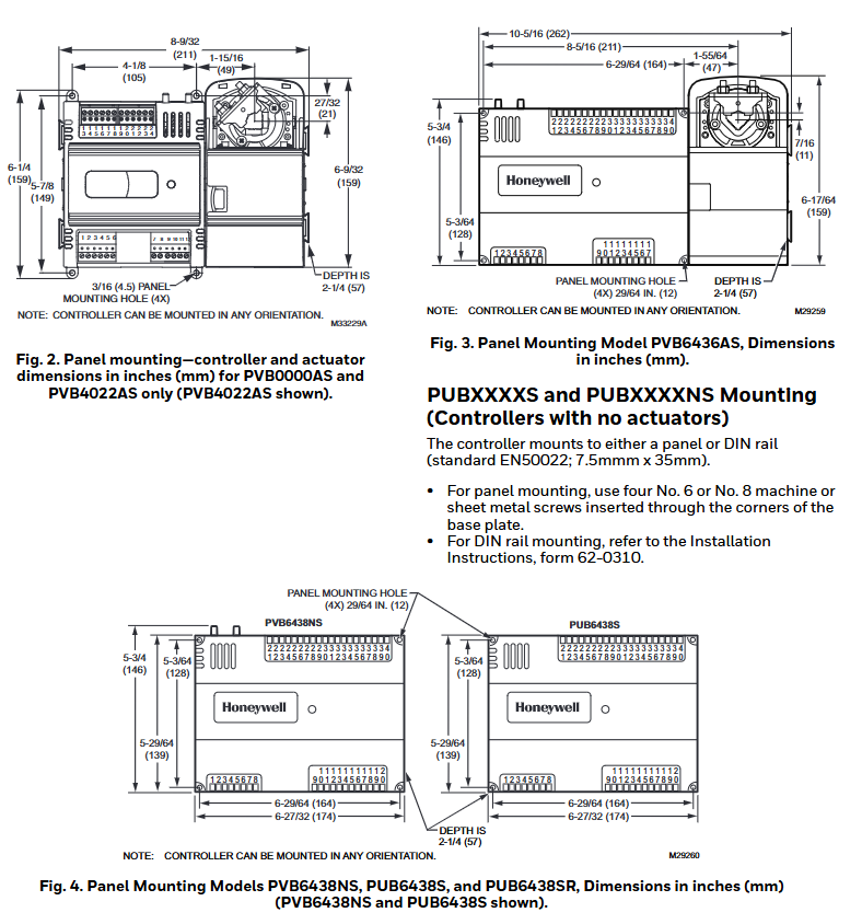
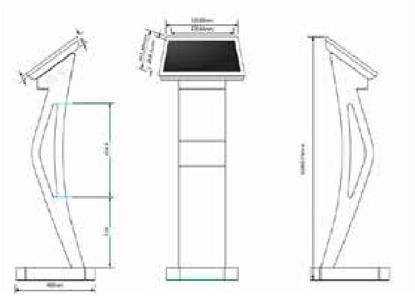
Dimensions (H/W/D)

See Fig. 1 to Fig. 4 beginning on page 6 for dimensioned drawings.

PUB1012S, PUB4024S, and PVB4024NS:6.25 x 4.81 x 2.26 in. (15.92 x 12.20 x 5.74 cm)

PVB0000AS, PVB4022AS (including Actuator):6.60 x 8.28 x 2.26 in. (16.70 x 21.10 x 5.74 cm)

PVB6436AS (including Actuator): 6.27 x 10.316 x 2.26 in.(15.92 x 26.20 x 5.74 cm)

PVB6438NS: 5.76 x 6.85 x 2.26 in. (14.62 x 17.40 x 5.74 cm)

PUB6438S, PUB6438SR: 5.45 x 6.85 x 2.26 in. (13.84 x 17.40 x 5.74 cm)

Hardware (PVB0000AS, PUB1012S, PUB4024S, PVB4022AS, and PVB4024NS)

CPU

Each controller uses a 32 bit ATMEL ARM 7 microprocessor.

Memory Capacity

Flash Memory: 512 kilobytes. The controller is able to retain Flash memory settings for up to ten (10) years.

RAM: 128 kilobytes

Controller Status LED

The LED on the front of the controller provides a visual indication of the status of the device. When the controller receives power, the LED appears in one of the following allowable states, as described in Table 3.

Hardware (PUB6438S, PUB6438SR, PVB6436AS, and PVB6438NS)

CPU

Each controller uses a pair of microprocessors. The first is a 16-bit Texas Instruments MSP430 family microprocessor that is used to manage the Inputs, Outputs and Control. The second is a 32-bit ATMEL ARM 7 microprocessor that manages communication for the Spyder BACnet.

Memory Capacity

Flash Memory: 372 kilobytes. The controller is able to retain Flash memory settings for up to ten (10) years.

RAM: 72 kilobytes

MS/TP MAC Address

The MS/TP MAC address for each device must be set to a unique value in the range of 0-127 on an MS/TP network segment. DIP switches on the Spyder BACnet controller are used to set the controller’s MAC address.

Device Instance Number

The Device Instance Number must be unique across the entire BACnet system network because it is used to uniquely identify the BACnet devices. It may be used to conveniently identify the BACnet device from other devices during installation. The Spyder BACnet Controllers Device Instance Number is automatically set when it is added to a WEBStation-AX project. The Device Instance Number can be changed by the user, which may be necessary when integrating with a third party or when attempting to replace an existing controller and it is desired to maintain the existing Device Instance Number.

Termination Resistors

Matched terminating resistors are required at each end of a segment bus wired across (+) and (-). Use matched precision resistors rated 1/4W ±1% / 80 – 130 Ohms. Ideally, the value of the terminating resistors should match the rated characteristic impedance of the installed cable. For example, if the installed MS/TP cable has a a listed characteristic impedance of 120 Ohm, install 120 Ohm matched precision resistors.

Shield Terminating

Following proper MS/TP cabling shield grounding procedures is important to minimize the risk of communication problems and equipment damage caused by capacitive coupling. Capacitive coupling is caused by placing MS/TP cabling close to lines carrying higher voltage. The shield should be grounded on only one end of the MS/TP segment (typically the router end). Tie the shield through using the SHLD (terminal 4) on the Spyder BACnet Controller.

Sylk™ Bus

Sylk is a two wire, polarity insensitive bus that provides both 18 VDC power and communications between a Sylkenabled sensor and a Sylk-enabled controller. Using Sylkenabled sensors saves I/O on the controller and is faster and cheaper to install since only two wires are needed and the bus is polarity insensitive. Sylk sensors are configured using the latest release of the Spyder Tool for WEBPro and WEBStation.

Honeywell TR40, TR42 Room Sensors and Displays

Basic information

Product Name: TR40 and TR42 Series Room Sensors and Displays

Design purpose: Used in conjunction with Trend IQX controllers, it has an integrated temperature sensor and some models also include relative humidity and/or carbon dioxide concentration sensors. TR42 has a monochrome backlit LCD display screen, configurable to display sensor readings, and allows users to control fan speed, occupancy status, and temperature set points.

Connection method: Up to 7 devices can be connected via two-wire Sylk ™  The bus is connected to the controller and simultaneously transmits data and power.

Physical property

Dimensions: 84mm (width) x 121mm (height) x 21mm (thickness)

characteristic:

Single power/data connection to the controller reduces wiring.

Equipped with temperature sensing function, some versions come with humidity and/or carbon dioxide sensing.

Can operate in Celsius or Fahrenheit.

Universal backplane and connections for easy upgrading from TR40 to TR42.

Unique to TR42: Backlit LCD display screen that can display temperature, humidity, carbon dioxide, fan status, occupancy status, and set points, etc; It has the functions of setting points, fan speed, and occupancy status coverage.

Function

Equipment type and sensor

This series includes two main types: TR40 room sensors and TR42 room displays. All models have integrated sensors for measuring ambient temperature, and some models also include sensors for measuring humidity and/or carbon dioxide levels:

The output value of the sensor can be read by the connected controller. TR42 also has a display screen that can show sensor values and is combined with various control buttons for viewing and changing system operations.

Display and buttons of TR42

Main display screen: In normal operation, the “home” screen can be configured to display various information, such as temperature, humidity, carbon dioxide values, current fan status, current occupancy status, etc. The display backlight will turn off after about 1 minute of button free operation and return to the home screen.

Function buttons: There are two function buttons, whose functions are indicated by labels (or icons) displayed above. On the home screen, there may be main functions such as “FAN”, “OVERRIDE”, “More”, and secondary functions such as “HOME”, “EDIT”, “DONE”, and “CANCEL” in the control screen and menu.

Up and down buttons: The functions are different in different display modes and configurations. On the home screen, the current setpoint can be raised or lowered (if the function is enabled), and pressing them at the same time will display the “More” menu; In editing mode, the display value can be adjusted or the available settings can be browsed step by step.

Fan status and control

The home screen can be configured to display the current fan status/speed, and the fan operation can be configured in multiple modes. If the fan control is enabled, the home screen will display the “FAN” function button, allowing users to overwrite the current fan status. After making changes through the up and down buttons, users can press “CANCEL” to keep the existing status or “DONE” to save the new status.

Occupation status and control

The home screen can be configured to display the current occupancy status. If the occupation coverage control is enabled, the home screen will display the “OVERRIDE” function button, allowing users to overwrite the occupation status. After changing through the up and down buttons, they can press “CANCEL” to keep the existing status or “DONE” to save the new status. After the coverage is enabled, it can be configured to automatically cancel after a preset time or a specific network bypass time, and users can also manually cancel it at any time.

Setpoint adjustment

If the set point adjustment is enabled, pressing the up and down buttons from the home screen allows the user to adjust the temperature set point between the preset high and low limits. The set point adjustment screen has two formats: numerical and graphic. It can be changed in increments of 1 ° or 0.5 ° by pressing the up and down buttons. Press “CANCEL” to keep the existing set point or “DONE” to save the new set point.

More “menu

Multiple additional display values and settings can be accessed through the “More” function button (if displayed) or by simultaneously pressing the up and down buttons. Users can browse using the up and down buttons. Menu items can be individually configured to display or hide, with editable items labeled as “EDIT” on the right function button. Once selected, you can use the up and down buttons to change the value. Press “CANCEL” to keep the current value or “DONE” to save the new value.

Honeywell XNX Universal Transmitter

Basic information

Product Name: XNX Universal Transmitter

Core features: Compatible with all Honeywell gas sensor technologies, supporting multiple industry standard output signals, suitable for various gas detection scenarios, with advantages such as flexibility, universality, and global certification.

Product advantages

Flexibility

Compatible with all Honeywell gas sensor technologies, the best sensor technology can be selected for each application.

Supporting multiple industry standard output signals, able to adapt to changes in on-site requirements and adjust configurations, and preparing for future new output standards.

Universal transmitter platform

Simplify installation and reduce costs, minimize training time and expenses, reduce the possibility of misreading information and making incorrect changes to settings, and reduce maintenance, spare parts inventory, and costs.

Global certification

Obtained certifications in Europe, the United States, Canada, and other regions, compliant with ATEX, UL, and CSA standards, as well as ATEX, UL, and CSA performance certifications, meeting the IEC61508 SIL 2 standard.

Ease of Use

Equipped with an easy to read multilingual backlit LCD, displaying information through text, bar charts, numbers, and icons.

Supports local or remote sensor installation options, with the option to choose between current injection, current pulling, or isolated 4-20mA output to accommodate preferred wiring topology.

Standard equipped with HART ®  Communication function, convenient for remote diagnosis and configuration.

Reduce operating costs

Fully configured with non-invasive magnetic switches, no thermal work permit required.

Hot swappable toxic gas and oxygen sensor cartridge, catalytic and infrared sensors are repairable and automatically suppress during maintenance.

Friendly installation

Built in surface mount earbuds or optional pipe or ceiling mount brackets.

There are 5 M25 or three-quarters “NPT cable/conduit/sensor entrances, and the plug-in” POD “module can be removed for easy access to the terminal area. The detachable plug/socket terminal block is convenient for wiring.

Typical application scenarios

Suitable for offshore oil and production platforms, oil and gas exploration and drilling, refineries, chemical and petrochemical plants, onshore oil and gas terminals, natural gas transportation, power stations, and other scenarios.

Sensor compatibility

Compatible with all industrial fixed gas sensors in Honeywell’s analytical instrument series, including Searchline Excel, Searchpoint Optima Plus, Sensepoint (HT and PPM), and Model 705. Please refer to the individual data manuals for each sensor for details.

Main components and configuration

Main components

POD: Personality, Options and Display module.

Shell: available in painted marine grade aluminum alloy or 316 stainless steel version, with explosion-proof performance.

Other: Intrinsic Safety (IS) Barrier (for optional local HART) ®  Interface and electrochemical sensor interface), installation earpiece, optional local IS HART ®  Input ports, cable entrances, etc.

Configuration

There are three basic personalities (configurations) that support different types of sensors:

MV (Millivolt) Personality: Used for all mV signal input sensors, such as MPD, Sensepoint HT, PPM, and Model 705.

EC (electrochemical cell) personality: used for XNX EC toxic and oxygen sensors.

IR (Infrared) Personality: Used for Searchline Excel open circuit and Searchpoint Optima Plus point infrared gas detectors.

Install options

Supports multiple installation methods, including vertical or horizontal pipe installation (using optional pipe mounting brackets), ceiling installation, surface installation, in pipe installation, and optional remote sensor installation kit for XNX EC sensors (other sensor accessories depend on the sensor type).

Electrical specifications

Input voltage range: EC and mV versions 16 to 32Vdc, IR version 18 to 32Vdc (nominal 24Vdc).

Maximum power consumption: XNX EC (toxic) 6.2 watts; XNX mV (catalytic or infrared battery) 6.5 watts; XNX IR 9.7 watts with Searchpoint Optima Plus; XNX IR 13.2W with Searchline Excel receiver.

Current output: fully configured isolated 4-20mA and HART ®  Output module, providing current sink, current source, and isolation mode (supporting HART) ® 6.0 Protocol).

4-20mA signal accuracy: ± 1% of full scale.

Terminal: Cage style pluggable, with fixing screws, suitable for wires ranging from 0.5mm ² to 2.5mm ² (approximately 20AWG to 14AWG).

Honeywell H365 Series Addressable Heat Detectors

Basic information

Product Name: Fire Lite ®  The Alarm H365 series address coded heat detectors include models such as H365 (A), H365R (A), H365HT (A), etc.

Purpose: Designed specifically for Honeywell Fire Lite’s address coded fire alarm control panel, used for fire detection and can directly replace the H355 series.

Product Features

System and Address Encoding

SLC circuit: It adopts a two-wire SLC circuit connection and is wired through the base.

Address coding: Supports device address coding, and sets the address of each detector by rotating the decimal address switch, making it easy to accurately locate the fire location. For specific device capacity, please refer to the Fire Lite panel manual.

Structure and Design

Compliant with UL 268 7th edition standard.

Adopting a fashionable, low profile modern design, equipped with advanced thermistor technology for fast response.

Integrated communication function and built-in device type recognition function, with tamper proof features, built-in function test switch, can be activated by external magnets.

Operational performance

Temperature setting:

The fixed temperature model (H365 (A)) is factory preset to 135 ° F (57 ° C).

The temperature rise rate model (H365R (A)) is 15 ° F (8.3 ° C) per minute.

The high temperature model (H365HT (A)) is factory preset at 190 ° F (88 ° C).

LED indicator: Two LED indicator lights, red flashing in normal state, red constantly on when in alarm, LED flashing every time it is voted, with a viewing angle of 360 °.

Mechanical and other characteristics

The sealed design can resist back pressure, and SEMS screws are used for wiring on independent bases, suitable for direct surface installation or electrical box installation. It can be inserted into independent bases for easy installation and maintenance, and allows for the exchange of photoelectric, ion, and thermal sensors.

Support panel remote testing function, walking test with address display, low standby current.

Option: Can be connected to the remote LED output connection of the optional RA100Z remote LED annunitor.

Installation instructions

Use a detachable base to simplify installation, service, and maintenance, and each detector comes with installation instructions.

The detector base (of all types) is installed on an electrical bottom box at least 1.5 inches (3.81 centimeters) deep, compatible with junction box reference DF-60059.

Due to the inherent monitoring provided by SLC circuits, there is no need for terminal resistors, and only Style 4 (Class “B”) wiring allows for “T-shaped taps” or branches.

When using a relay or speaker base, refer to installation table I56-3626 in I300 (A) to understand the equipment limitations between the isolator module and the isolator base.

Application scenarios

For detailed information on detector spacing, layout, zoning, wiring, and special applications for property protection, please refer to I56-6525 “System Smoke Detector Application Manual”.

Construction and Operation

Construction: Made of fire-resistant plastic that meets commercial standards and has a beautiful appearance.

Operation: Each H365 series detector uses an address on the Fire LiteJCI signal line circuit (SLC) panel (the total limit depends on the panel), responds to regular polling from the control panel and reports its type and status. When receiving a test command from the panel (or local magnet test), it activates its electronic device and reports an alarm. The LED flashes when polling and lights up when receiving a panel command.

Product line information

The suffix “- IV” indicates CLIP and LiteSpeed devices, while the suffix “A” indicates the Canadian version.

Including multiple models such as H365, H365A, H365-IV, H365A-IV, etc., suitable for different scenarios and standards.

Intelligent base: There are multiple models, such as B300-6, B300-6-IV, B300A-6, etc. Different models have differences in color, size, function, and certification.

Installation kit and accessories: including TR300 series replacement flange, RA100Z (A) remote LED annunitor, test magnet, color kit, etc.

System specifications

Physical specifications

Size:

Detector height: 2.0 inches (5.3cm)

Base diameter:

B300-6 base: 6.1 inches (15.6cm)

B501 base: 4 inches (10.2cm)

Complete base list reference DF-60983

Shipping weight: 3.4 ounces (95g)

Environmental Specifications

Working temperature range:

H365, H365R series: -4 ° F to 100 ° F (-20 ° C to 38 ° C)

H365HT series: -4 ° F to 150 ° F (-20 ° C to 66 ° C)

Relative humidity: 10% -93%, non condensing

Detector spacing:

UL certification: maximum center to center distance of 50 feet (15.24m)

FM certification: 25 x 25 feet (7.62 x 7.62m)

Thermal performance specifications

Fixed temperature set point: 135 ° F (57 ° C) (H365 series)

Temperature rise rate detection: 15 ° F (8.3 ° C)/minute (H365R series)

High temperature set point: 190 ° F (88 ° C) (H365HT series)

Electrical specifications

Voltage range: 15-32VDC peak

Standby current (maximum average): 200 µ A @ 24VDC (communication every 5 seconds, LED enabled)

Maximum current: 4.5mA@24VDC (ON state)

Installation specifications

Installation method: Equipped with B300-6 (A) flange base (standard), other bases refer to “Product Line Information: Smart Base”

Compatible with bottom box: An electrical bottom box at least 1.5 inches (3.81cm) deep, compatible with junction box reference DF-60059

Certification and Standards

UL/ULC certification: S2517

FM certification: Passed

CSFM certification: 7272-0075:0501

Quality Management: Compliant with ISO 9001 standard

Honeywell Universal Marshalling Solution for Safety Systems

Product Introduction

Overview

This document provides technical information on the components of the Release R100 security system universal grouping solution, which provides standardized grouping functionality for centralized and distributed installations. The solution processes 16 I/O points through signal conditioning components, including disconnection and fuse (default), and can optionally insert signal conditioning adapters (SCA) for isolation, intrinsic safety, relay, and other functions as needed.

Range

The universal grouping solution components covered include various signal conditioning components, adapters, barrier adapters, etc., such as CC-USCA01, CC-UPTA01, FC-UUDI501, etc.

Definition

USCA(Universal Signal Conditioning Assembly): A component that accommodates 16 adapters, on-site wiring connections, and large-scale terminal cable connectors.

IOTA (Input Output Termination Assembly): A component that accommodates IOM and on-site wiring connections.

IOM (Input Output Module): A device that contains most of the electronic devices required to perform specific I/O functions and can be plugged into IOTA.

Product Features

Provide three-level flexible on-site terminals to meet various on-site wiring requirements.

The signal conditioning adapter can be inserted into USCA without the need for separate installation of isolators, relays, signal converters, and barriers.

USCA integrates (optional) fuses and knife switch disconnect devices for easy factory installation and maintenance.

Provide D-Sub connectors for interfacing with IOTA.

Provide on-site power to USCA through system integration cables (SIC) from secure IOTA.

Provide optional power connectors to power active signal conditioning adapters.

16 plug and play signal conditioning adapters are available for selection.

Vertical installation is convenient for wiring, and most on-site wiring needs to enter from the top or bottom of the cabinet.

Relays and active signal conditioning adapters are equipped with LEDs for maintenance personnel to quickly view status information.

USCA integrates multiple functions, including plug and play adapters (optional signal conditioning), onboard flexible process signal terminals, onboard connections with secure IOTA, onboard on-site power distribution, receiving 24 VDC power, on-site disconnection, on-site melting, and testing probe points.

Universal Grouping Solution Function

CC-USCA01 Universal Signal Conditioning Component: Backplane component, capable of accommodating 16 signal conditioning modules. Each channel’s on-site terminal integrates fuse and knife switch disconnection functions. The safety system side interface connects all 16 channels through a single large-scale terminal cable (SIC) and can be installed on DIN rails.

CC-UPTA01 Universal Direct Adapter: A single channel direct module that allows safety systems or safety field terminals (live and return) to be directly connected to field devices without the need for an external power source.

FC-UDI501 digital input adapter with 5K resistor: SIL 3 single channel input module, equipped with 5K Ohm shunt resistor, suitable for low-voltage applications. The adapter output interfaces with field devices, and the input side is connected to the safety system without the need for external power supply.

FC-UIR501 Digital Input Relay Adapter with 5K Resistance: SIL 1 Single Channel Relay Isolation Input Module, equipped with 5kOhm shunt resistor, suitable for low voltage applications. The relay coil side is connected to the field interface, and the contact side is connected to the safety system, powered by the field.

FC-UDR01 digital input relay adapter: SIL 3 single channel isolated digital input relay module, suitable for low-voltage applications, coil side and field interface, contact side connected to safety system, requiring external power supply.

FC-UDOR01 digital output relay adapter: SIL 3 single channel normally open relay output module, suitable for low-voltage applications, with contact side interface with field devices and coil side connected to safety systems, without the need for external power supply.

FC-UDOF01 F&G digital output relay adapter: SIL 3 single channel normally open relay output module, suitable for low-voltage applications, capable of driving high current field devices, with contact side interface with field devices, coil side connected to safety systems, and no external power supply required.

Honeywell D06F Pressure Reducing Valve

Application scope

According to the EN 806-2 standard, this type of pressure reducing valve is used to protect household water facilities from excessive water supply pressure, and can also be used for industrial or commercial applications within its specification range. Installing a pressure reducing valve can avoid pressure damage, reduce water consumption, maintain a constant set pressure (even if the inlet pressure fluctuates greatly), and reduce flow noise in the facility.

Authentication

DVGW certification

WRAS certification (temperature not exceeding 23 ° C)

Compliant with BS EN 1567 standard

All materials are certified by UBA, ACS, and SWRAS

Special Features

The inlet pressure is balanced, and the fluctuation of inlet pressure does not affect the outlet pressure

Products with a size of 1 ¼ “are LGA certified, low-noise, belong to Group 1, and have no restrictions

The valve core is made of high-quality synthetic materials and can be completely replaced

Set the water outlet pressure by rotating the adjustment knob, and the set pressure is directly displayed on the set point scale

Adjust the spring to avoid contact with drinking water

Built in fine filter

A version without accessories can also be provided

Technical data

Medium: drinking water

Connection/Size:

Connection size: 1/2 “-2”

Nominal size: DN15- DN50

Pressure value:

Maximum inlet pressure with transparent filter bowl: 16 bar

Maximum inlet pressure with brass filter bowl: 25 bar

Outlet pressure: 1.5-6 bar

Preset outlet pressure: 3 bar

Minimum pressure drop: 1 bar

Working temperature:

Maximum working temperature of media with transparent filter bowl: 40 ° C

Maximum working temperature of medium with brass filter bowl: 70 ° C (* maximum working pressure 10 bar)

Note: If the valve may be exposed to ultraviolet radiation or solvent vapors, please use an SM06T brass filter bowl.

Structure

Overview of Component Materials

-High quality synthetic material for spring valve cover with adjustment knob and setting scale

-Valve body with pressure gauge interface on both sides made of anti zinc brass

-External thread connection (options A and B) brass

-Pressure gauge interface-

-Filter bowl made of transparent synthetic material or brass

-Adjust the spring steel of the spring

-Complete valve core with diaphragm and seat, high-quality synthetic material, EPDM diaphragm

-Stainless steel fine filter with 0.16 mm mesh

-Pressure gauge (see attachment) made of high-quality synthetic materials

-Sealing element EPDM

Working principle

The spring-loaded pressure reducing valve operates through a force balancing system. The force of the diaphragm opposes the force of the regulating spring. When the outflow pressure decreases due to water intake (resulting in a decrease in diaphragm force), the greater force of the spring will open the valve, causing the outflow pressure to increase until the force between the diaphragm and the spring is balanced again. The inlet pressure has no effect on the opening or closing of the valve, so fluctuations in inlet pressure will not affect the outlet pressure, thus achieving inlet pressure balance.

Transportation and Storage

The parts should be kept in their original packaging and opened before use. The following parameters should be followed during transportation and storage:

Environment: clean, dry, dust-free

Minimum ambient temperature: 5 ° C

Maximum ambient temperature: 55 ° C

Minimum relative humidity: 25% (non condensing)

Maximum relative humidity of the environment: 85% (non condensing)

Installation guide

INSTALLATION REQUIREMENTS

Installed in a horizontal pipeline with the filter bowl facing downwards

Install globe valve

Downstream equipment should be protected by a safety valve (installed downstream of the pressure reducing valve), and the output pressure of the pressure reducing valve should be set to be at least 20% lower than the response pressure of the pressure relief valve according to EN 806-2 standard

The installation location should be antifreeze and easily accessible

The pressure gauge should be easy to read

Equipped with a transparent filter bowl, it is easy to check the degree of pollution

Easy to maintain and clean

Installed downstream of the filter or mesh

Provide a straight pipe section at least five times the nominal size of the valve after the pressure reducing valve (in accordance with EN 806-2 standard)

Regular maintenance is required according to EN 806-5 standard

Installation Example

Standard installation examples include water meters, globe valves, check valves, filter units, pressure reducing valves, etc. Valves of different nominal sizes have corresponding installation distance requirements.

Honeywell CR-6A Six Relay Control Module 

Product specifications

Normal operating voltage: 15-32 VDC

Standby current: 1.45 mA

Alarm current: 32 mA (assuming all six relays have switched once and all six LEDs are continuously on)

Temperature range:

ULC application: 32 ° F to 120 ° F (0 ° C to 49 ° C)

EN54 application: -10 ° C to 55 ° C

Humidity:

ULC application: 10% to 95%, non condensing

EN54 application: 10% to 93%, non condensing

Size: 6.8 inches high x 5.8 inches wide x 1.0 inches deep (173mm high x 147mm wide x 25mm deep)

Maximum IDC wiring resistance: 40 ohms

Accessories: BB-2A cabinet, BB-6A cabinet, CH-6A chassis, or appropriately grounded metal cabinet

Wire gauge: 12-18 AWG (0.9mm ² -3.25mm ²)

Relay current: 30 mA/relay pulse (15.6ms pulse duration, under panel control)

Preparation before installation

This information is only provided as a quick reference installation guide. If modules are installed in the existing operating system, operators and local authorities should be notified that the system will be temporarily suspended.

Disconnect the power supply of the control panel before installing the module.

This system contains static sensitive components. Before handling any circuit, it is necessary to ground it with a suitable wrist strap to eliminate static charges on the body.

The enclosure cabinet should be made of metal material and properly grounded.

This manual should be left to the owner/user of this device.

Product overview

Purpose: Suitable for intelligent alarm systems, used for Form-C switching applications, load circuits do not require wiring monitoring.

Structure: Each module provides a set of independent dry-type relay contacts, which can be wired as normally open or normally closed; Each module has its own address, and the address of the first module is set to 01 to 94 through a pair of rotary encoding switches. The remaining modules are automatically assigned to the next five higher addresses; Disable up to three unused modules to release addresses for use elsewhere; Each CR-6A module also has a green LED indicator light controlled by the panel, which can make the LED flash, lock on or lock off.

Includes: 6 1 × 3 terminal blocks, 1 1 × 4 terminal block, 2 1.25-inch (32mm) supports, 3 mechanical screws, 1 splitter (note: in the disabled position, a maximum of one splitter can be installed at the same time)

Compatibility requirements

To ensure normal operation, this module should only be connected to compatible control panels.

Component

Installation options:

Up to six CR-6A modules can be installed on the CH-6A of the BB-6A cabinet

One or two CR-6A modules can be installed in the BB-2A cabinet

Chassis: CH-6A chassis is used to install CR-6A modules in the BB-6A cabinet. It can accommodate up to six CR-6A modules in a single cabinet row, three modules wide and two modules deep; The BB-2A cabinet has a built-in chassis that can accommodate one or two CR-6A modules. The front CR-6A module position of each chassis is lower than the rear CR-6A module position, so that all status indicators are visible.

Cabinet: BB-6A cabinet can accommodate CH-6A chassis with up to six CR-6A modules installed; The BB-2A cabinet accommodates one or two CR-6A modules on its internal chassis, and the cabinet dimensions refer to the cabinet installation document.

Installation steps

Cabinet installation: Install the bottom box using the four holes provided on the back of the cabinet in a clean and dry area.

Chassis installation: The CH-6A chassis is installed in the BB-6A cabinet and secured to the two PEM bolts on the rear wall of the cabinet with two 8-32 hex nuts, which are provided with the chassis; The BB-2A cabinet comes with an installed chassis and does not require additional installation.

Module installation: There are two methods to install modules at the rear of the chassis.

Method 1: Install only the rear module and do not install any modules in front of it.

Method 2: Install the rear module, and another module will be installed in front of it. All necessary screws and supports are provided with the module.

Wiring requirements

All wiring must comply with applicable local codes, regulations, and laws.

Install module wiring according to the engineering drawings and corresponding wiring diagrams.

When making electrical connections, strip approximately 0.25 inches (6.35mm) of insulation from the end of the wire, slide the exposed end of the wire under the clamp, and then tighten the clamp screws.

Set the address on the module according to the engineering drawing, use the rotary encoding switch to set the address of the first module (between 01 and 94), and the remaining modules will be automatically assigned to the next five higher addresses. For example, if the base address switch is set to 28, the next five modules will be addressed as 29, 30, 31, 32, and 33. The minimum address cannot be set to 94 or above, otherwise other modules will be assigned to non-existent addresses.

Provide a splitter to disable up to three unused modules. The module is disabled starting from the highest address and moving downwards. For example, if the shunt with “address disabled” is placed on “2” and the base address switch is set to 28, the module will be assigned to 28, 29, 30, and 31.

Precautions for Relay Connection

The relay contacts on CR-6A can be connected to power limited or non power limited power sources, but the wiring must be kept at least 0.25 inches (6.35mm) away from all power limited wiring.

The power limiting circuit must use FPL, FPLR, or FPLP type cables as required by NEC Article 760.

For ease of wiring, allocate all power limiting wiring to one side instead of alternating with non power limiting wiring.

Honeywell PlantCruise by Expert C300 Controller

Basic Overview

Honeywell’s C300 controller is PlantCruise by Expert ®  The platform provides powerful and robust control functions. Its core is the field validated Deterministic Control Execution Environment (CEE) core software, which uses the easy-to-use and intuitive engineering tool Control Builder to configure and load control strategies. The C300 controller hardware adopts an innovative Series 8 exterior design, which has unique advantages in space saving, installation, and maintenance, and can be configured with redundancy by adding an additional identical hardware module.

Main advantages

Improve engineering efficiency: With a rich library of features and a seamless and intuitive user environment, it facilitates the creation and implementation of control strategies.

Maximizing process runtime: With powerful diagnostic capabilities and complete hardware redundancy, it reduces maintenance work and minimizes downtime to the greatest extent possible.

Reduce production costs: By implementing flexible and efficient control strategies, online migration, and efficient hardware processing capabilities, production costs can be reduced.

Core functions

Control Execution Environment (CEE)

Support ISA S88.01 batch standard, integrate sequences with devices, enable devices to track sequence status and perform pre configured operations based on status, reducing the complexity of handling abnormal situations.

The execution cycle of the control strategy can be set within the range of 50 milliseconds to 2000 milliseconds. Users can modify or add new strategies to existing strategies without interrupting the execution of other control strategies by the controller, and can fully control the execution order of functional blocks within the control strategy and the execution order of multiple control strategies.

Function block support

The functional blocks that control the execution environment support continuous control, logic based control, sequential control, and model-based control. Each functional block contains rich predefined functions, such as alarm limits and priorities, various control algorithms, and maintenance statistics, all of which are configurable parameters. Function blocks are linked together in the control module to perform specific control tasks, providing a foundation for efficient control engineering.

Data communication

Parameters provide access to various information in the controller, which can be used throughout the entire Expert system. Each parameter is protected from accidental changes through a secure access level, and some parameters can only be changed offline. Communication is based on anomaly reporting and publish subscribe mode, accessing data only when needed to avoid data duplication and efficiently utilize communication bandwidth.

Engineering environment

Control Builder is a control engineering and maintenance tool that controls the execution environment, simplifying configuration through a graphical user interface and predefined functional blocks, and improving the work efficiency of control engineers. Control engineers do not need to build standard functional blocks from scratch to enable and modify these features, and can also use embedded objects such as text, documents, or web links to add document descriptions to control policies.

On-line monitor

After loading the control strategy into the C300 controller, engineers can use the same graphical interface to monitor the strategy online, which helps validate the control strategy or troubleshoot process issues. Control or maintenance engineers can directly modify parameters from the engineering environment without the need for an operator interface.

Controller based model predictive tuning (ProfitLoop)

ProfitLoop is a patented algorithm from Honeywell that provides single input/single output model prediction function blocks, which are included in the standard C300 controller function block library. It has the operational simplicity and computational efficiency of standard PID function blocks, while providing tight and robust control, which can improve process stability by up to 30%. A simple model for the creation process of ProfitLoop, which predicts the impact of control actions on process (controlled) variables, can predict future process behavior, and accurately determine the adjustment required to achieve the expected control objectives of the process.

Custom Algorithm Blocks (CABs)

Custom algorithm blocks are similar in purpose and structure to the native feature blocks included in Control Builder, but have user-defined algorithms and data structures. CABs are developed using Visual Basic integrated into Control Builder. The C300 controller supports executing CABs in the Expert LX, greatly reducing the workload required to create complex control strategies that require a robust control environment provided by the C300.

Honeywell Expert Series-C I/O Specification

Product Introduction

Overview

This document provides expertise ®  Technical information on the configuration of Series C I/O and C300 controllers, which will be released starting from the Expert R300 version.

Range

The Series C I/O products covered include various types such as digital inputs, digital outputs, analog inputs, analog outputs, low-level multiplexers, pulse inputs, and general-purpose input/output.

definition

IOTA (Input Output Termination Assembly): A component that accommodates IOM and on-site wiring connections.

IOM (Input Output Module): A device that contains most of the electronic devices required to perform specific I/O functions and can be plugged into IOTA.

Product Features

Innovative design: Supports enhanced thermal management and significantly reduces size compared to similar products.

Integrated design: I/O modules and field terminals are combined in the same area, without the need for separate chassis to accommodate electronic components.

Detachable terminals: Two levels of “detachable” terminals, convenient for factory installation and maintenance.

Power supply: Provide on-site power through IOTA, without the need for additional power or manual wiring.

Redundancy support: Implement redundancy directly on IOTA without the need for external wiring or redundant control devices.

Installation design: Vertical installation facilitates wiring; The “information circle” provides quick visual prompts; The “tilted” design effectively manages the heat inside the cabinet.

Circuit protection: The input and output circuits have short-circuit protection, eliminating the need for circuit fuses and reducing installation and maintenance costs.

Series C I/O selection and size

Selection advantages

In almost all configurations, the C300 controller and Series C I/O provide practical and maintainable process equipment connections in a smaller space, helping to reduce overall installation costs.

MODULE SIZE

Simulation modules typically have 16 points, with 6-inch (152mm) IOTA used for non redundant applications and 12 inch (304mm) IOTA used for redundant applications.

The discrete module has 32 points, with 9-inch (228mm) IOTA used for non redundant applications and 12 inch (304mm) IOTA used for redundant applications.

I/O module functionality

Including various functional modules such as high-level analog input/with HART input, high-level analog input/without HART, analog output/with HART output, etc., each module has different functions and characteristics.

Specific module specifications

Analog Input Module

CC-PAIH01/02 (with HART): Supports high-level current or voltage input, 16 channels, multiple input ranges, and features extensive self diagnosis and optional redundancy.

CC-PAIH51 (with HART): accepts high-level current input from transmitters and sensing devices, 16 channels, supports only 4-20mA input.

CC-PAIX01/02 (without HART): Similar in function to CC-PAIH01/02, but does not support HART.

CC-PAIN01 (without HART): accepts high-level current input from sensing devices, with 16 channels.

Low level analog (temperature) input module

CC-PAIM01 (LLMUX): Supports up to 64 channels of temperature input, uses Honeywell PMIO LLMUX FTA, supports thermocouple (TC) and thermistor (RTD) inputs.

CC-PAIL51: Supports up to 16 channels of temperature input, each channel can be configured as a thermocouple or thermistor input, without the need for an external Process Manager FTA.

Pulse input module (CC-PPIX01)

Provide the ability to monitor various pulse input field values for the Expert C300 controller, support the “quick cut-off” function, suitable for metering and trade handover applications, with 8 input channels and 2 output channels.

Analog output module

CC-PAOH01 (with HART): Provides high-level constant current to actuators and recording/indicating devices, with 16 output channels and multiple features.

CC-PAOH51 (with HART): Similar in function to CC-PAOH01, supports HART status and configuration.

CC-PAOX01 (without HART): Provides standard 4-20mA DC output with 16 channels.

CC-PAON01 (without HART): Similar in function to CC-PAOX01.

Digital Input Module

CC-PDIL01 (24VDC): accepts 24VDC signals as discrete inputs, with 32 channels and multiple features.

CC-PDIL51 (24VDC): Similar in function to CC-PDIL01, without open circuit detection.

CC-PBIS01 (Event Sequence): accepts 24VDC discrete signals, can be time stamped to support event sequences with 1ms resolution, and has 32 channels.

CC-PDIH01 (high voltage): accepts signals such as 120VAC/125VDC, 220VAC as discrete inputs, with 32 channels.

Digital Output Module

CC-PDOB01 (Bus based 24VDC): Provides reliable 24V digital output signals, 32 channels, and multiple features.

Relay IOTA (using CC-PDOB01 IOM): Provides dry contacts for isolated low voltage/low current or high voltage/high current discrete output applications, with 32 output channels.

CC-PDOD51 (drain type 24VDC): switchable reliable 24V digital output signal, 32 channels.

Universal Input/Output Module

CC-PUIO01: Interface with field devices for analog input, analog output, digital input, and digital output, with 32 channels, each channel can be configured for multiple types.

CC-PUIO31: Similar in functionality to CC-PUIO01, it supports more features such as event sequences.

Functional matrix

Provides a table to assist in selecting I/O modules and IOTA with similar functional characteristics, including AI, AO, DI, DO function matrices, to facilitate users in selecting suitable modules and IOTA based on their needs.

Honeywell WIN-PAK Access Control System

Brand background

Honeywell is a Fortune Global 500 high-tech enterprise with businesses covering aviation, building and industrial control technology, specialty materials, and the Internet of Things. In China, all four of its major business groups have settled down, with Shanghai as the Asia Pacific headquarters and over 50 wholly-owned and joint ventures in more than 30 cities, employing approximately 11000 people, of whom 20% are research and development personnel.

Honeywell Intelligent Building Technologies (BA) has over 30000 employees worldwide, with products, software, and technology applied to more than 10 million buildings worldwide. Its business units include building automation, fire protection, security, intelligent living solutions, and building intelligent systems.

WIN-PAK access control system

System Overview

The WIN-PAK access control system has complete functions, high cost-effectiveness and reliability, and is widely used in government, government agencies, banks, residential areas and other fields, meeting the needs of small and medium-sized projects with high security performance requirements and relatively complex applications. It has high reliability and is used by hundreds of thousands of users worldwide; Easy to use, with features such as quick launch guide, electronic map, and dynamic icons; Powerful functionality, supporting unlimited number of cardholders and doors, compatible with multiple controllers.

The system adopts a unified interface, which can integrate and manage functions such as access control, video surveillance, and anti-theft alarm. It provides an intuitive browser based interface that can perform common access control operations from almost anywhere. It can also be easily extended from a single site to a multi regional enterprise level solution, supporting the integration of multiple biometric technologies, and has API interfaces for customized integration.

Specification parameters

Different versions of WIN-PAK access control management software have differences in web browser support, system workstation/user count, anti-theft alarm integration, video integration, account/sub account, Suprema biometric, attendance (web module), API interface integration, and other aspects.

The system supports multiple access control systems, video systems, and alarm systems, and is compatible with operating systems SQL、 Browsers, VMWARE, etc. have specific requirements, support multiple languages, and have software support agreements (SSAs) to provide different levels of services.

The access controller

PRO4000 intelligent access control controller: suitable for medium to large entrance and exit management solutions, equipped with WIN-PAK access control platform, using 32-bit CPU structure and embedded Linux operating system. Cardholder and event data are stored in onboard flash memory and can be saved for a long time after power failure. Provide complete logic for multiple doors, support offline operation, can be connected to the main computer through TCP/IP network, supports both full network architecture and master-slave architecture for door management expansion, supports passive and active electric lock control methods, provides pre installed access control chassis, and has two door control controller models to choose from.

PRO42 modular access control controller: connected to WIN-PAK integrated security management server through network, providing various advanced functions. The PRO42IC intelligent controller supports hanging multiple input/output or card reading modules. The PRO42R2/PRO42R2B dual card reader module supports bidirectional encrypted OSDP communication protocol and Wiegand card reader interface. The PRO42OUT and PRO42IN provide multiple relay outputs and monitored alarm inputs, respectively, and have multiple chassis suitable for different installation methods.

Fingerprint scanner and card reader

The JT-MCR series intelligent card reader can enhance the flexibility, scalability, and security of access control systems. It can read multiple standard smart cards, and different models have different specifications in terms of maximum card reading distance, working frequency, supported ISO standards, card reading content, keyboard signal output, working temperature, working humidity, power supply, output interface, certification, size, weight, and other aspects.

Intelligent Quick Pass Door Series

HASE-1000 indoor/outdoor wing gate: equipped with 16 pairs of high-density infrared precise detection of traffic status, LED lights indicating direction for entry and exit, safety anti pinch and other functions, widely used in various places. There are different models of side roads and middle roads, with rich supporting accessories and detailed parameters in terms of structure, specifications, etc.

HASE-2000 Indoor Double Swing Lock: With 20 pairs of high-density infrared detection, LED light indication for entry and exit, safety anti pinch and anti impact functions, it has a wide range of application scenarios, including side and middle channels, various supporting accessories, and clear structural and specification parameters.

Electromagnetic lock and accessories

The HL series electromagnetic lock products come in various specifications to meet the installation needs of different door types, and there are also multiple waterproof models suitable for outdoor environments. Including magnetic locks with different tensile strengths such as 300 pounds, 600 pounds, 1200 pounds, and 1500 pounds, as well as anode locks, cathode locks, and various installation brackets, switch buttons, emergency release buttons, and other accessories. Each product has detailed specifications and ordering information.

HOCP One Card System

System Overview

The HOCP series is a Honeywell one card management system, which includes various functions such as basic platform, access control, attendance management, consumption system, visitor management, etc. It realizes universal use of one card and is widely used in various places. It seamlessly integrates with the WIN-PAK access control management system, integrating security and flexibility.

The HOCP one card server uses Linux operating system, pre installed database and platform software, supports web and desktop clients, and can be extended through server cascading.

FUNCTION

The basic platform includes holiday management, personnel information management, electronic maps, operator management, log management, etc; The access control module integrates the WIN-PAK access control system; Visitor management has a complete process; Attendance management supports multiple attendance methods and related configurations; Consumer management is a system that combines online and offline methods; Ladder control management supports two deployment methods; Patrol management supports multiple patrol methods and task formulation; Parking management supports multi site management, entrance and exit control management, parking space detection, parking guidance, reverse car search, etc. The platform has clear device access restrictions and also supports various other functions and API interfaces.

Related equipment

This includes various devices such as the HOCP-BPSVR one card server, HOCP-BPMRW IC card issuer, HARB-FR6700 7-inch facial recognition all-in-one machine, HARB-FR3400 4-inch facial recognition all-in-one machine, HARB-FP2000 fingerprint recognition machine, HOCP-VSPIM person card comparison visitor machine, etc. Each device has its own functional characteristics, specification parameters, and ordering information.

Search for products

Back to Top
Product has been added to your cart