Call us 24/7uaedcs@163.com
Welcome to the official website of CNIACS Automation Technology Co., Ltd!
Call us 24/7uaedcs@163.com

Woodward ProTech GII overspeed protection device

Product description

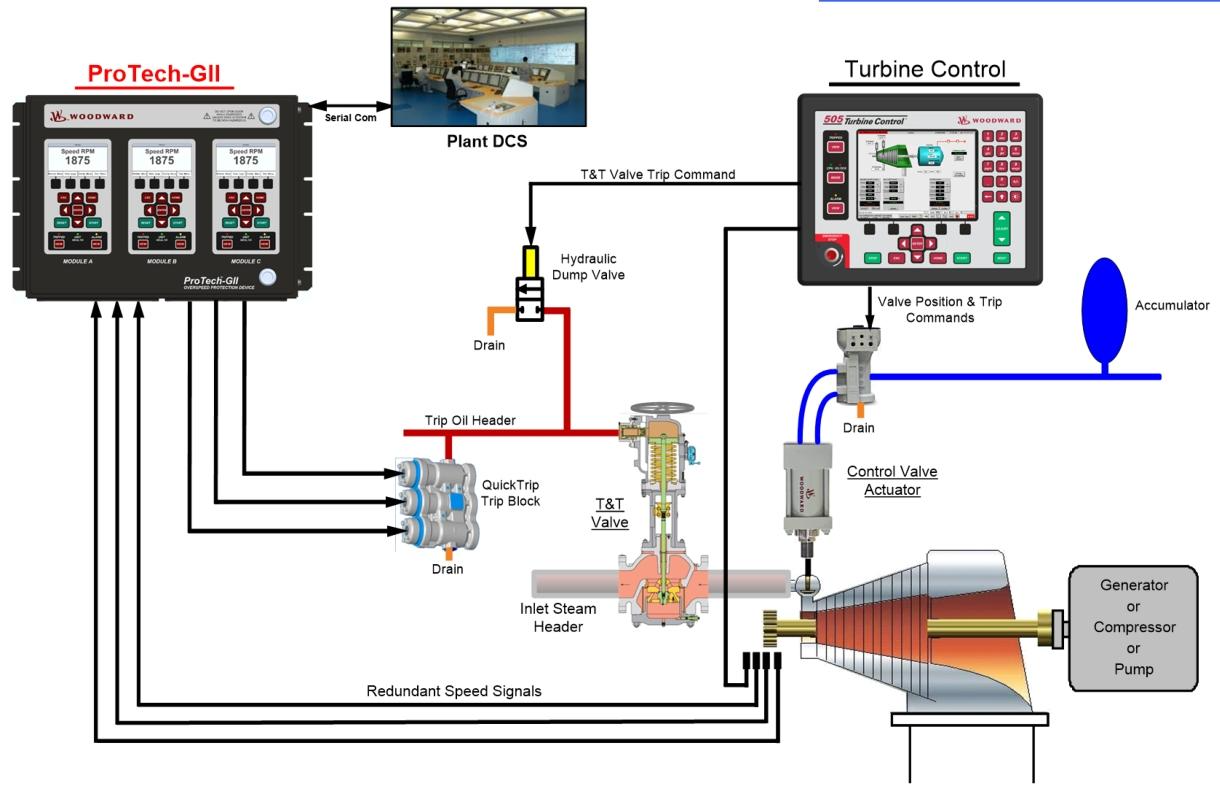
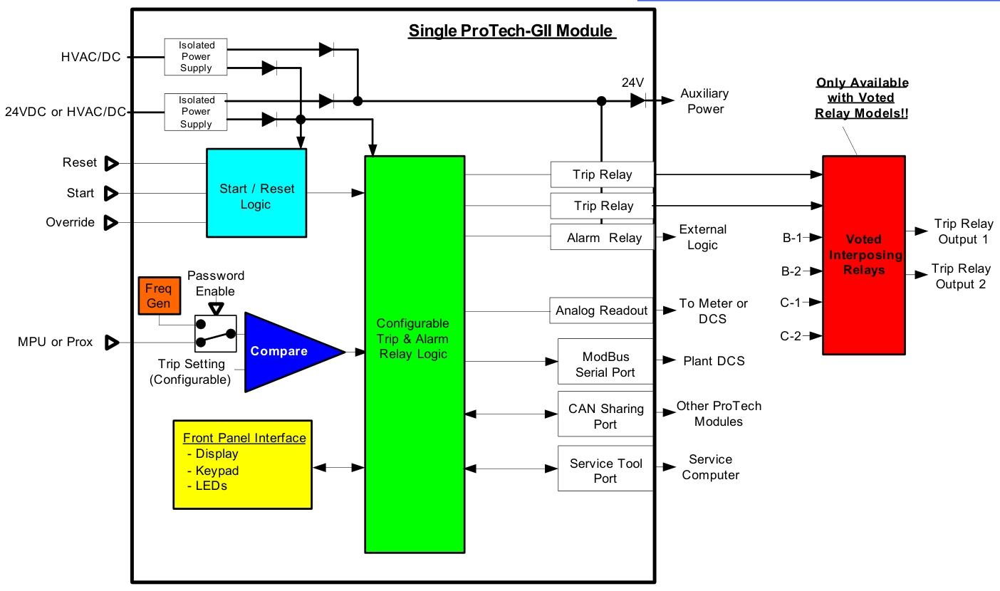
ProTech GII is an overspeed safety device designed to safely shut down steam, gas, and water turbines of all sizes when overspeed or over acceleration events are detected. It accurately monitors the turbine rotor speed and acceleration through active or passive magneto electric sensors (MPUs), and sends shutdown commands to the turbine’s trip valve or corresponding trip system.

According to the system design, ProTech GII has two output types: two dual redundant trip relay outputs using a 2-out-of-3 voting architecture, or three independent non voting trip relay outputs. Its independent alarm relay, 4-20 mA speed reading, and Modbus ®  Communication function makes it easy to integrate into any turbine safety system.

The device comes in embedded models (designed for installation inside a standard 24 inch (610 mm) cabinet front door) and wall mounted models (designed for installation on walls or bases near turbines). When installed inside the casing, it is suitable for harsh environments and has a protection level of IP56 (dustproof, completely preventing water jets similar to giant waves).

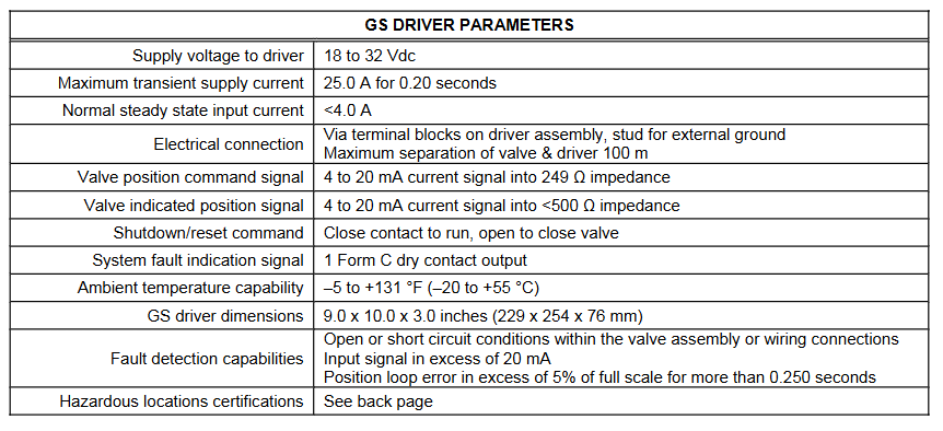
To improve reliability, each ProTech GII module (A, B, C) can accept two high voltage power inputs (90-240 Vac/100-150 Vdc) or one high voltage power input (90-240 Vac/100-150 Vdc) and one low voltage power input (18-32 Vdc) depending on the purchased model. This design is based on the principle of high signal selection, allowing the device to operate normally when either or both power sources are available.

Application scenarios

ProTech GII is used to safely shut down steam, gas, and water turbines when turbine overspeed or over acceleration events are detected. Its 12 millisecond response time and speed range of 0.5 to 80000 rpm make it suitable for various types and sizes of turbines.

It can be used in conjunction with turbine control or trip systems, and interfaces with related control systems or factory DCS (distributed control system) through redundant hard wired input and output signals or triple redundant serial Modbus communication ports. An Ethernet gateway can also be selected to easily access the factory Ethernet network.

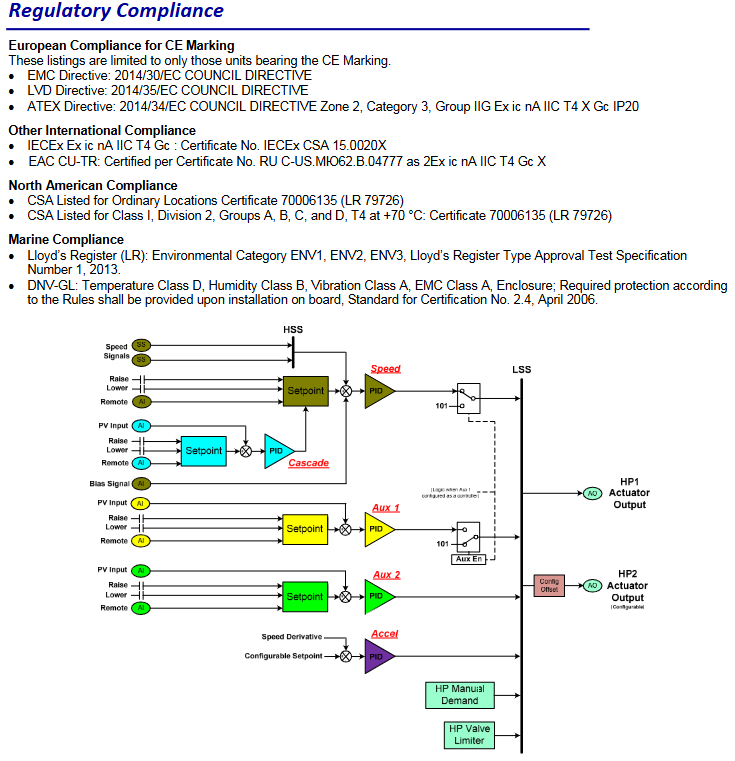
As a safety device certified by IEC61508 SIL-3 (Safety Integrity Level 3), it can be easily applied to safety systems based on IEC61508 or IEC61511.

Main functions and features

Online testing: Each ProTech GII module can be manually tested through the module front panel, Modbus communication port, or automatically tested through its automatic testing program functionality. Allow users to configure overspeed testing, which is automatically executed on a regular basis, testing each module (A, B, C) one by one, recording each test result, or stopping testing when an error is detected.

Online maintenance: The triple module design allows users to easily replace one of the modules (A, B, C) while the turbine is running normally online. The plug and play structure of the device’s backplane and its module to module learning function improve the convenience of replacement.

Trip, alarm, and overspeed logs: The log function records all trip, alarm, trip valve response times, and overspeed events. The trip log function uses a rolling buffer to record the last 50 detected trip or alarm events and the last 20 overspeed events along with their respective times in memory. Each log file can be viewed from the front panel of the device or downloaded to the computer through the ProTech GII service tool program. Each module uses non-volatile memory to ensure that all recorded events can be saved even in the event of a power outage.

Real time clock: Each ProTech GII module uses a real-time clock to ensure accurate time recording. Special time averaging function is used between modules to ensure clock synchronization.

Acceleration detection: configurable to protect the turbine from high acceleration events. Use the derivative of the velocity signal to detect turbine acceleration and issue relevant trip commands.

MPU detection: The speed sensor input of each module uses a special MPU disconnection detection circuit to verify whether the MPU is correctly connected before the turbine runs, and uses special speed loss detection logic to verify the MPU function during the turbine runs.

Automatic overspeed testing program: It can be configured to periodically perform overspeed testing on each module, and then record and report the test results. Simulate overspeed conditions through an internal frequency generator to complete the test sequence for each module.

Anti sulfur pollution: Using special conformal coating materials, it has excellent long-term protection against H2S and SO2 gases in the 3C2 environment specified in the international standard IEC 721-3-3 1994.

Configuration information

Collocation method

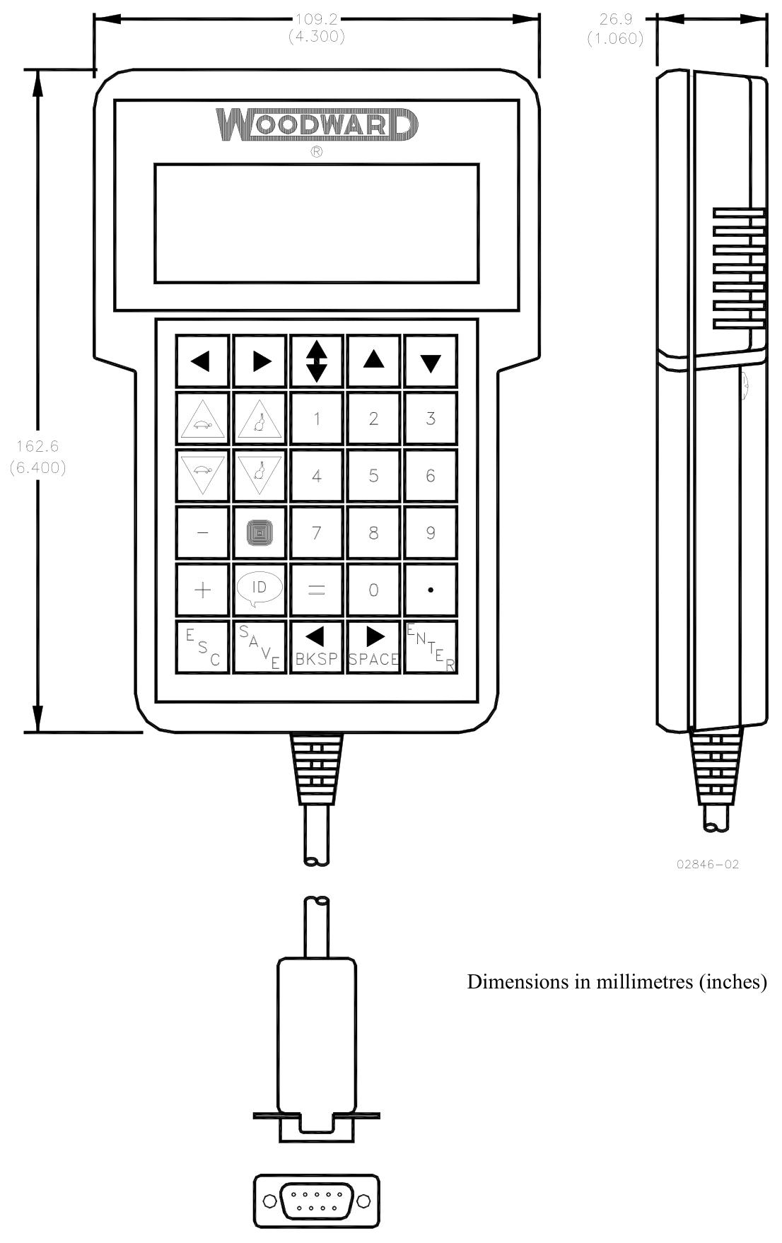
ProTech GII can be configured (programmed) through its front panel keyboard or software service tools running on on-site computers or laptops. For ease of use, all configuration settings, alarm/trip, and overspeed logs can be viewed through the high-resolution 4.2-inch (107 mm) color display screen of each module.

Configure auxiliary functions

The special inter module learning function can reduce configuration time and lower error rates.

Different levels of password security mechanisms are used to protect device configuration settings and restrict access to device testing functions.

Input signal configuration

Power supply

High voltage power supply: 88-264 Vac/47-63 Hz; 90–150 Vdc, Power of 90 W, supporting 2 redundant inputs.

Low voltage power supply: 18-32 Vdc, power 100 W.

Speed signal: 1 channel per module, a total of 3 channels, configurable to receive the following signals

Magnetic electric sensors (MPUs): 100-32000 Hz, 1-35 Vrms.

Proximity probe: 0.5-25000 Hz, 24 Vdc.

Gear teeth range: 1-320 teeth.

Discrete input: Each module has 3 channels, totaling 9 channels, including alarm/trip reset commands, start commands, and speed fault coverage commands.

Output signal configuration

Discrete output relay

Voting relay model: 2-channel total shutdown relay output (2-out-of-3 voting), rated at 8 A @ 220 Vac or 8 A @ 24 Vdc; Each module has 1 alarm relay output, totaling 3 channels, with a rated value of 2 A @ 24 Vdc.

4-20 mA analog output: 1 channel per module, for a total of 3 channels, specifically designed for speedometer readings.

Communication ports: Each module has 1 channel, totaling 3 channels, which are serial RS-232, RS-422, RS-485 Modbus ports.

Other configuration related information

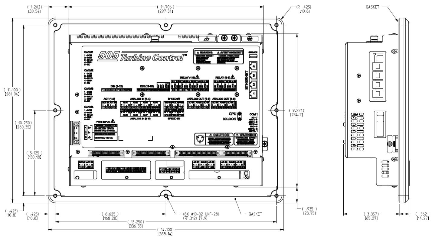
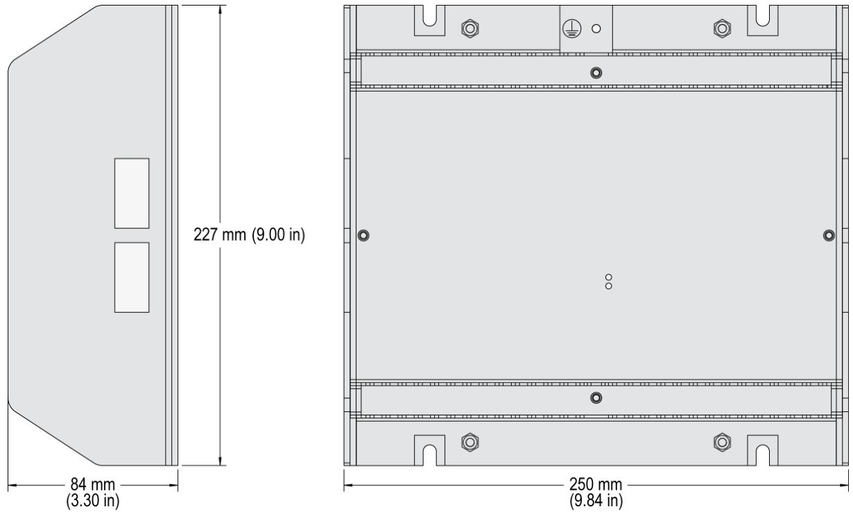
The installation size (including panel) is approximately 330 x 445 x 159 mm (13 x 17.5 x 6.25 inches).

According to the ordered part number, it is designed to be wall mounted or base mounted, or vertically embedded in panels or cabinets.

The protection level is IP56.

The working/storage temperature range is -20 to+60 ° C.

Woodward SPM-D10 series single circuit breaker synchronizer

Application scenarios

SPM-D10 is a microprocessor based synchronizer suitable for three-phase AC generators equipped with Woodward or other compatible speed controllers and automatic voltage regulators. It achieves automatic frequency, phase, and voltage matching through analog or discrete output bias signals, and the model 8440-1668 SPM-D1040B/XN can directly replace the SPM-A synchronizer.

Main functions and features

Synchronization function

Capable of phase matching, slip frequency synchronization, and voltage matching.

Perform two-phase detection on the generator and busbar.

There are selectable operating modes, such as SPM-A (Run, Check, Allow, and Close).

Can perform synchronous checks and synchronous time monitoring.

Isolation operation: capable of frequency control and voltage control.

Dead bus operation: Circuit breakers can be closed as needed.

Control output

Standard configuration: There are discrete up/down outputs for speed and discrete up/down outputs for voltage.

X and XN packages: Voltage and speed analog bias outputs can be freely configured for all levels (various configurations such as ± 1V, ± 3V, 0 to 5V, 0.5 to 4.5V, ± 10V, ± 5V, 0 to 20mA, ± 20mA, etc.); The speed bias output can be configured as a 500Hz PWM output and an adjustable voltage level; Two up/down outputs can be configured as speed or voltage outputs.

Operational Characteristics

Two row LCD display screen is used for operation and alarm indication, with synchronous oscilloscope function, which can indicate control activities and circuit breaker status.

Equipped with multi-level password parameter protection function, it can be configured directly or through a PC, and the language can be adjusted between English or German.

Specification parameters

Accuracy: Level 1.

power supply

Standard: 24 Vdc (± 25%).

N and XN packaging: 90 to 250 Vac/dc.

Inherent power consumption: maximum 10W.

environmental condition

Environmental temperature: -20 to 70 ° C; N and XN packages are -20 to 60 ° C.

Environmental humidity: 95%, non condensing.

Voltage parameters

Rated/Δ voltage: [1] 66/115 Vac or [4] 230/400 Vac; Maximum value (V max): [1] 150 Vac or [4] 300 Vac; Rated phase to ground voltage: [1] 150 Vac or [4] 300 Vac; Rated surge voltage: [1] 2.5 kV or [4] 4.0 kV.

Measurement frequency: 40 to 70Hz; linear measurement range up to 1.3 times rated voltage; Input resistance: [1] 0.21 M Ω, [4] 0.696 M Ω; maximum power consumption per path:<0.15W.

Discrete input: With isolation function, the maximum input range is 250 Vac or DC, and the input resistance is about 68 k Ω.

Relay

Equipped with isolation function, the contact material is AgCdO.

Load (GP): 2.00 Aac@250  Vac、2.00  Adc@24  Vdc、0.36  Adc@125  Vdc、0.18  Adc@250  Vdc。

Guided load (PD): 1.00 Adc@24  Vdc、0.22  Adc@125  Vdc、0.10  Adc@250  Vdc。

Shell and connection

Shell type: APRANORM DIN 43700.

Size: 144 × 72 × 122 mm; Front panel cut: 138 [+1.0] × 67 [+0.7] mm.

Connection: Depending on the connector, it can be a screw/plug terminal, 1.5 mm ² or 2.5 mm ².

Woodward SPM-D11 series load sharing synchronizer

Application scenarios

SPM-D11 is a microprocessor based synchronizer suitable for single-phase or three-phase AC generators equipped with Woodward or other compatible speed controllers and automatic voltage regulators. It achieves automatic frequency, phase, and voltage matching through analog or discrete output bias signals, combined with synchronous, load and power factor control or synchronous load sharing of a circuit breaker, as well as generator protection functions.

Main functions and features

Synchronization function

Capable of phase matching, slip frequency synchronization, and voltage matching.

Perform two-phase detection on the generator and busbar.

There are selectable operating modes, such as SPM-A (Run, Check, Allow, and Close).

Can perform synchronous checks and synchronous time monitoring.

Load/reactive power sharing

It can perform parallel operation of the power grid, active power control, and true effective value power calculation. The active power setting value of the generator can be set through parameters (2 values) or 0/4 to 20mA.

Support soft uninstallation and power factor control, with the power factor setting value set through parameter settings.

There are power limit values and relay outputs.

Isolation operation

Can perform frequency control and voltage control.

Dead bus operation

Circuit breakers can be closed according to demand.

Protection function

Perform single-phase current transformer detection and two-phase voltage detection on the generator.

Equipped with generator overvoltage/undervoltage, overclocking/underfrequency, reverse/reduced power (32R/F), and overload protection functions.

Control output

The voltage and speed analog bias output of LSXR package can be freely configured for all levels (various configurations such as ± 1V, ± 3V, 0 to 5V, 0.5 to 4.5V, ± 10V, ± 5V, 0 to 20mA, ± 20mA, etc.).

The speed bias output can be configured as a 500Hz PWM output and adjustable voltage level.

Two up/down outputs can be configured as speed or voltage outputs.

Operational Characteristics

Two row LCD display screen is used for operation and alarm indication, with synchronous oscilloscope function, which can indicate control activities and circuit breaker status.

Equipped with multi-level password parameter protection function, it can be configured directly or through a PC, and the language can be adjusted between English or German.

Specification parameters

environmental condition

Environmental temperature: -20 to 70 ° C.

Environmental humidity: 95%, non condensing.

Electrical parameters

Rated/Δ voltage: [1] 66/115 Vac or [4] 230/400 Vac; Maximum value (V max): [1] 150 Vac or [4] 300 Vac; Rated phase to ground voltage: [1] 150 Vac or [4] 300 Vac; Rated surge voltage: [1] 2.5 kV or [4] 4.0 kV.

Measurement frequency: 40 to 70Hz; linear measurement range up to 1.3 times rated voltage; Input resistance: [1] 0.21 M Ω, [4] 0.696 M Ω; maximum power consumption per path:<0.15W.

Rated current (I rated): [1]../1A, [5]../5A; Linear measurement range up to 3.0 times rated current; Load:<0.15 VA; Rated short-time current (1s): [1] 50 × I rated, [5] 10 × I rated, with isolation function.

Input range: 12/24VDC or 18 to 250 Vac/dc; Input resistance: approximately 6.8 k Ω or 68 k Ω.

Relay

Equipped with isolation function, the contact material is AgCdO.

Load (GP): 2.00 Aac@250  Vac、2.00  Adc@24  Vdc、0.36  Adc@125  Vdc、0.18  Adc@250  Vdc。

Guided load (PD): 1.00 Adc@24  Vdc、0.22  Adc@125  Vdc、0.10  Adc@25

image.png

Woodward TG-13 and TG-17 speed controllers

Overview

Introduction: This manual (04042C) provides overall instructions, installation, operation, adjustment, operating principles, troubleshooting, and replacement of spare parts for Woodward TG-13 and TG-17 governors.

Describe

TG-13 and TG-17 are mechanical hydraulic differential governors used to control steam turbines that do not require synchronous (constant speed) operation.

The maximum rotation angle of the output shaft of the governor is 40 °, and the recommended angular travel from no-load to full load is 2/3 of the governor’s full travel.

The maximum working capacity of TG-13 is 12.2 foot pounds, and TG-17 is 17.5 foot pounds (at 40 ° full stroke of the governor).

The internal gear pump has different size specifications, suitable for different standard speed ranges such as 1100 to 2400 rpm, 2400 to 4000 rpm, 4000 to 6000 rpm, etc.

During operation, the internal oil pressure of TG-13 is 1034kPa (150psi), while the oil pressure of TG-17 is 1379kPa (200psi).

The governor housing comes in two types: cast iron and cast aluminum. There is a speed difference type, and the internal adjustment setting has a difference rate before leaving the factory. The speed adjustment methods include screw type (standard configuration) and lever type (optional configuration).

The rotation direction of the drive shaft is unidirectional and can be changed on site. The cast iron casing needs to be adjusted internally, while the cast aluminum casing can be adjusted externally (by removing 4 bolts and rotating the pump body 180 °).

Simple maintenance, few coupling parts, fully enclosed design, internal circulation of pressure oil, oil level indicator mounting holes on both ends of the shell, easy to check the oil level.

Install

Introduction: When handling and installing, be careful to avoid hitting the transmission shaft, output shaft, speed setting shaft or speed control screw, to prevent damage to the seal, internal parts and factory settings. Do not use the speed control transmission shaft as a support to place the speed control.

Reception: The speed controller is fixed on a wooden base with bolts when shipped from the factory, vertically placed and packed in a packaging box. There are oil level indicators on both sides of the shell, and the oil filling cover is installed in a vertical installation and operation position. After factory testing and calibration, the rear seat is empty, sealed and painted. There is a small amount of oil film on the surface of the internal parts to prevent rust, and the exposed shaft is sprayed with rust proof oil. There is no need to clean or rinse the interior before installation, operation or retesting.

Storage: It can be stored directly in the short term. In harsh environments or long-term storage, it is necessary to refuel and follow the packaging instructions in Woodward manual 25075 “Packaging for Commercial Storage of Mechanical Hydraulic Controllers”. If the oil cap is in a horizontal running position and needs to be placed vertically, the oil cap and screw plug should be removed and replaced before oil injection to prevent leakage.

Drive shaft rotation direction

Looking down from the top of the governor, define the direction of rotation of the drive shaft, and mark the nameplate with “CW” (clockwise) or “CCW” (counterclockwise).

The transmission shaft has only one rotation direction, and the rotation direction viewed from the top should be the same as the rotation direction of the engine transmission shaft viewed from the mounting seat downwards. Otherwise, the oil pump cannot establish oil pressure, resulting in component heating and rotating component jamming.

Change the rotation direction of the transmission shaft

Governor with eccentric gear pump not on the lower body: Remove the governor and drain the oil, place it flat with the cooling joint facing up, rotate the transmission shaft so that the keyway is facing up, loosen the 4 pump body bolts, remove the pump body, rotate the eccentric ring so that the pin hole is close to the desired direction arrow, insert the pin, install the inner and outer gears, install the pump body on the transmission shaft and tighten it, confirm that the transmission shaft rotates flexibly, install the sleeve stop ring and leave the gap.

Gear pump eccentric speed regulator on the lower body: Remove the 4 bolts of the pump body, rotate the pump body 180 °, align the pump body arrow with the reference point of the housing. If it is screw speed regulation, screw in the speed screw clockwise. If it is lever speed regulation, turn the speed setting shaft to the maximum fuel position and hold it. Install the bolts and confirm that the transmission shaft rotates flexibly. Remove the upper cover to confirm that the sleeve rotates with the transmission shaft.

Governor installation

It can be installed horizontally or vertically. The oil cap and drain plug are installed in the factory in the vertical running position. If installed horizontally, they need to be moved to the corresponding position to ensure that the power piston is completely immersed in oil, and the oil level indicator also needs to be moved to the correct position.

Ensure sufficient space for installing connecting rods and performing oil maintenance, confirm correct rotation direction and speed range, correctly position the drive shaft and connect it to the turbine

Woodward 505E (Extraction/Inlet) Steam Turbine Digital Controller

Application scenarios

The 505E controller is designed for single extraction and/or inlet steam turbines of various sizes and applications, and can start, stop, control, and protect single extraction and/or inlet steam turbines or turbine expanders that drive generators, compressors, pumps, or industrial fans. Its unique PID structure is suitable for controlling steam equipment parameters, such as turbine speed, load, inlet pressure, exhaust manifold pressure, extraction or inlet manifold pressure, or tie line power. The controller achieves stable control during normal operation of the steam turbine through special PID to PID logic, and switches to disturbance free control mode in case of equipment abnormalities, reducing process overshoot or undertuning.

Product description

Hardware and appearance

Adopting industrial grade reinforced casing, it can be installed in the system control panel of the factory control room or next to the turbine.

The front panel combines programming station and operator control panel (OCP) functions, with a user-friendly interface that facilitates engineers to program according to specific factory requirements. Operators can easily start and stop the turbine and enable/disable any control mode, with password security protection program mode settings. The two-line display screen of the equipment allows the operator to view the actual and set values on the same screen, simplifying the operation of the turbine.

The input and output wiring of the turbine interface is located on the lower back panel of the controller, and the pluggable terminal block is convenient for system installation, troubleshooting, and replacement.

Core features: on-site configurability, integrated operator control panel, integrated first issue indicator logic, user-friendly menu format, online (standalone) configuration changes, large LED display screen Modbus ®  Communication function, integrated valve decoupling and protection calculation logic, multiple decoupling modes, and the use of sulfur resistant conformal coating.

Cost benefit design

The 505E controller integrates turbine control, system sequence controller, operator control panel, and first output indicator functions, reducing external system equipment and system installation, wiring, and troubleshooting work. This controller can be configured on site, and professional factory personnel can make major functional changes on site. Minor functional changes can be made online when process changes require it. Its first indicator logic can indicate internal and external system related alarm and shutdown situations, greatly simplifying and reducing system troubleshooting work.

Communication function

The 505E controller can be controlled through two Modbus protocols ®  The communication ports directly communicate with the factory distributed control system and/or CRT based operator control panel, and these ports support RS-232, RS-422, and RS-485 communication using ASCII or RTU Modbus protocols. It can also communicate with the factory DCS through a hard wired connection, and all 505E PID settings can be controlled through analog input signals without sacrificing interface resolution and control performance.

System protection

It has functions such as integrated overspeed protection logic, first out indication (10 independent shutdown inputs), turbine operating range limiter, disturbance free switching between control modes when sensor faults are detected, local/remote control priority and selection, and fail safe shutdown logic.

Control function 

Available PID controllers: speed/load PID (with dual dynamic characteristics), extraction/intake PID, auxiliary PID (limiter or controller), cascade PID (manifold pressure or tie line control).

Control capability: including speed/frequency control, extraction/inlet manifold pressure control, turbine or generator load control or limitation, turbine inlet manifold pressure control or limitation, turbine exhaust manifold pressure control or limitation, factory inlet and outlet power control or limitation, synchronous load distribution between units (with DSLC) ™ Control, etc.

Main features: critical speed avoidance (3 speed bands), automatic start program (hot start and cold start), valve limiter, safety protection (password protected program), dual speed/load dynamic characteristics, first out indication (shutdown), zero speed detection through proximity probe (<0.5Hz), overspeed trip peak speed indication, two programmable function keys on the 505E front panel, two independent Modbus communication links, remote simulation settings for speed/load, extraction/admission, auxiliary and cascade, program upload/download function, compressor feedforward decoupling algorithm, etc.

Control Specifications

Input

Power supply: Supports multiple power inputs, including 18-32 Vdc、90–150 Vdc、88–132 Vac(47–63 Hz)、180–264 Vac(47–63 Hz)

Speed: 2 magneto electric sensors (MPUs), input range 1-30 Vrms; Or proximity probe (providing 24 Vdc power supply), frequency range 0.5 to 15 kHz

Discrete inputs: There are a total of 16 contact inputs, of which 4 are dedicated inputs and 12 are programmable inputs

Analog inputs: 6 programmable current inputs, with an input range of 4-20 mA

Output

Valve/actuator driver: 2 actuator outputs with an output range of 4-20 mA or 20-160 mA

Discrete output: 8 relay outputs, of which 2 are dedicated outputs and 6 are programmable outputs

Analog output: 6 programmable current outputs, with an output range of 4-20 mA

Woodward 723 Generator Controller

Application and Overview

The Woodward 723 generator controller is suitable for various generator application scenarios, including auxiliary generators and diesel electric propulsion in ship systems, as well as islanding mode operation and basic load operation on infinite power grids in power plant systems. It has closed-loop speed control function, equipped with torsion filter and notch (band stop) filter, which can alleviate low-frequency oscillation problems caused by engine, generator inertia and flexible coupling. The controller has three operating modes, namely droop control based on 4-20mA megawatt sensor input or actuator position, synchronous load distribution with soft loading/unloading and automatic generator circuit breaker opening command after engine unloading, and megawatt control with soft loading/unloading and automatic generator circuit breaker opening command after engine unloading.

Hardware specifications

Model and output: The models include 8280-500, 8280-501, 8280-502, and 8280-503, which correspond to different voltages and output types. For example, 8280-500 is a high-voltage control with an actuator output of 0-200mA.

Power supply and power consumption: The power supply has 18-40Vdc (nominal 24 or 32Vdc) and 90-150Vdc (nominal 125Vdc), with a nominal power consumption of 40W.

input/output

Speed signal input: The frequency range of the magneto electric sensor is 400-15000Hz, and the proximity switch is 7.5-1000Hz.

Digital input: 8, 8mA at 24Vdc.

Analog inputs: 4, 4-20mA or 1-5VDC.

Analog output: 3, of which 2 are 4-20mA or 0-1mA (connected to instruments or computers), and 1 is 20-160mA or 4-20mA.

Output of actuator: 1, 20-160mA or 4-20mA.

Communication port: The communication port (J1) of the programmer is RS-422, 9-pin D-type connector, 1200 baud rate, full duplex; The communication ports (J2 and J3) are RS-232, RS-422 or RS-485, 9-pin D-type connector, 1200-38400 baud rate, full duplex.

Environmental parameters: working environment temperature -40 to+70 ° C (-40 to+158 ° F), storage temperature -55 to+105 ° C (-67 to+221 ° F), humidity at 38 ° C is 95%, anti electromagnetic interference/radio frequency interference complies with MIL-STD 461C (Parts 5 and 9) in the United States, humidity complies with MIL-STD 810D Method 507.2 Procedure III in the United States, mechanical vibration is a swept sine wave of 24-2000 Hz, constant acceleration of 2.5 Gs, resonance retention -1 million cycles, total time per axis is 3/4-6 hours, mechanical impact complies with MIL-STD 810C Method 526.2 Procedure I (basic design testing), Procedure II (transport drop testing, packaging) in the United States. Program V (Workbench Operation), salt spray complies with ASTM B 117-73.

Key points of installation

Unpacking and Inspection: Before installation, it is necessary to read the relevant content on electrostatic discharge protection. When unpacking, handle the electronic controller carefully and check for any damage. If there is any damage, immediately notify the shipper.

Power requirements: The high-voltage version requires a 90-150Vdc voltage source, and the low-voltage version requires an 18-40Vdc voltage source. Both have a maximum power consumption of 40W and should not exceed the input voltage range. If battery power is used, an AC generator or other battery charging equipment should be equipped.

Location selection: The installation location should consider ventilation, maintenance space, moisture resistance, distance from electromagnetic interference sources, and avoidance of vibration. The working temperature range is -40 to+70 ° C (-40 to+158 ° F), and it cannot be installed on the engine.

Electrical connection: All shielded cables must be twisted pair, and do not attempt to tin plated braided shielding layers. All signal lines should be shielded, and the shielding layer should be connected to the nearest chassis ground. The exposed length of wires outside the shielding layer should be as short as possible, not exceeding 50mm (2 inches). The other end of the shielding layer must be open and insulated from any other conductor. Do not lay the shielded signal line together with other wires carrying high currents.

System function

Engine speed related functions

Speed sensing: The controller has two speed sensing inputs, which can be configured as torsional filtering (to make operation smoother, suitable for flexible couplings) or high signal selection (to achieve speed sensing redundancy, enabled when one signal fails). If a torsion filter is used, the speed sensors should be located on both sides of the coupling; If high signal selection is used, the two speed sensing devices should be located on the same speed measuring disc. Speed sensor # 2 can also be configured to detect the speed of the turbocharger.

Speed filtering: Each speed sensor input has a low-pass filter that can filter out unwanted frequencies on the speed sensor. If tuned above 15.9Hz, the filter will be automatically disabled. In addition, a notch filter can be enabled, and its filtering frequency should be set to the resonance frequency of the velocity signal that needs to be filtered. The filtering Q factor can adjust the attenuation degree of the signal frequency filtered by the band stop filter.

Speed control: including idle speed, rated speed settings, overspeed trip function (starting and stopping when the set speed is reached to prevent overspeed), as well as minimum and maximum speed reference limits and acceleration/deceleration rate control.

Synchronization and load control function

Engine start: When the Run/Stop contact is closed (or configured to be open), the speed reference is at idle. When the engine speed exceeds the idle/rated switching speed, the speed reference will ramp up and down at an acceleration/deceleration rate to the rated speed, which can be interrupted by temporarily closing the deceleration contact. If the idle/rated selection function is enabled, after the engine is started, the idle or ramp to rated speed is determined based on the contact position.

Synchronization function: When the engine reaches the rated speed and maintains the synchronization readiness delay time within the synchronization readiness limit, the “ready synchronization” state is achieved through Modbus ®  Convey as True. The speed reference can be adjusted by inputting or adding or subtracting contacts through the unit synchronizer to achieve synchronization with the busbar. Alternatively, after the auxiliary contacts of the generator circuit breaker are closed, the bias speed reference can be input through the system synchronizer to achieve cross busbar connection or synchronization with the grid.

Droop control: When the synchronous/droop contacts are open and the auxiliary contacts of the generator circuit breaker are closed, the following droop modes operate. Calculate the speed droop value based on the droop percentage and engine load. The engine load comes from the input of the megawatt sensor. If the signal fails, it is determined based on the output position of the actuator. At the same time, provide a “droop pulse” function to prevent the engine from sinking into reverse power when connected to the bus in droop mode.

Synchronous load distribution: When the synchronous/droop contacts are closed, and the auxiliary contacts of the generator circuit breaker are closed and the load input signal is normal, synchronous load distribution is enabled. The first online machine immediately closes the relay K4 contact on its load sharing circuit. The subsequently selected synchronous units will adjust the load according to the automatic loading/unloading rate until the load shared with the synchronized units is within the specified load sharing error range. At this point, relay K4 closes to connect to the load sharing circuit and achieve load balancing. It also has an automatic soft unloading function. When the unloading contact is closed (instantaneously), the engine load decreases at an automatic unloading rate to the unloading trip level, and then a command to open the generator circuit breaker is issued.

Megawatt control: When the auxiliary contacts, grid contacts (if used), and megawatt control contacts of the generator circuit breaker are closed and the megawatt load input is not disabled, operate in megawatt control mode. The megawatt reference value can be adjusted by adding or removing contacts, or based on internal megawatt reference or remote reference (4-20mA or Modbus) ®) Adjustment. If the remote reference input fails, the megawatt reference will lock the last healthy value.

Protection and restriction functions

High/Low Frequency Protection: In megawatt control mode, it can be configured to open the grid and/or generator circuit breakers or switch to droop mode (megawatt coverage function) when the grid frequency is too high or too low.

Limiting functions: including start-up and maximum fuel limiter (limiting excessive fuel supply or flooding during engine start-up), engine shutdown limiter, frequency load limiter (limiting engine load when grid frequency exceeds preset limits during megawatt control), boost air pressure limiter (providing fuel limitation based on 4-20mA boost air pressure input signal), etc.

Load rejection function: When the generator circuit breaker or grid circuit breaker is opened and the load is above a certain level, the load rejection algorithm takes effect, driving the actuator output to zero for a period of time to reduce speed overshoot.

Woodward 505 Digital Control for Steam Turbines

Application scenarios

The Woodward 505 controller is designed for industrial steam turbines of various sizes and applications, and can start, stop, control, and protect industrial steam turbines or turbine expanders that drive generators, compressors, pumps, or industrial fans. Its unique PID structure is suitable for controlling steam equipment parameters, such as turbine speed, load, inlet manifold pressure, exhaust manifold pressure, or tie line power. It can achieve stable control and disturbance free mode switching during normal operation and equipment abnormalities, reducing process overshoot or overshoot.

Product description

Hardware and appearance

Adopting industrial grade reinforced casing, it can be installed in the system control panel of the factory control room or next to the turbine.

The front panel combines programming station and operator control panel (OCP) functions, equipped with an 8.4-inch (21cm) graphic display screen for engineers to program and operators to operate, and has password security protection program mode settings.

The input and output wiring of the turbine interface is located on the lower back panel of the controller, and the pluggable terminal block is convenient for system installation, troubleshooting, and replacement.

Core functions

It includes four PID controllers (speed, cascade, auxiliary 1, auxiliary 2), multiple startup programs (manual, semi-automatic, automatic, remote control), and multiple protection functions (overspeed, critical speed range, maximum power, etc.). Users can configure them according to specific turbine application requirements without the need for professional control engineers. After configuration, checks will be conducted to ensure there are no basic errors.

Equipped with on-site configurable, integrated graphical operator control panel, automatic start program, integrated first issue indicator, trip and alarm event recorder, user-friendly menu format, real-time trend screen, turbine running time log, real-time clock synchronization through SNTP, Ethernet communication and other features, it has the same appearance and function as the previous 505 version, adopts sulfur resistant conformal coating, and is certified for use in hazardous areas (low-voltage models).

Software tool

RemoteView software: It can be used as a remote operator control panel and/or engineering station, installed on remote computers or touch panels, and can perform all display functions of the 505 front panel. The password based login level security mechanism can manage the functional permissions of remote panel users.

Service tool suite: can download configuration settings files to 505, upload configuration settings files from 505 to other devices for saving, view real-time or saved trend files, etc.

Cost benefit design

The 505 controller integrates turbine control, system sequencer, operator control panel, and first output indicator functions, reducing external system equipment and system installation, wiring, and troubleshooting work. This controller can be configured on site, and professional factory personnel can make major functional changes on site. Minor functional changes can be made online when process changes require it. Its first indicator logic can indicate internal and external system related alarm and shutdown situations, greatly simplifying and reducing system troubleshooting work.

Communication function

The 505 controller can communicate with the factory distributed control system and/or CRT based operator control panel directly through four Ethernet ports using Modbus TCP or OPC communication protocols, or through a serial Modbus port. A single serial port supports RS-232 or RS-485 communication using ASCII or RTU Modbus protocols, and can also communicate with factory DCS through a hard wired connection.

Control function 

Available PID controllers: speed/load PID (with multiple dynamic and adaptive PID), extraction/intake pressure/flow PID, cascade PID (manifold pressure or tie line control), auxiliary PID 1 (limiter or control), inlet manifold PID, exhaust manifold PID, rotor acceleration PID (at start-up).

System Protection: Integrated overspeed protection logic and testing capabilities, first out indication (15 independent shutdown inputs), external alarm indication (15 independent alarm inputs), logic stuck in critical speed band, disturbance free switching between controls, local/remote control priority and selection, internal CPU watchdog circuit (to prevent faults), password security for operation and configuration modes.

Control Specifications

Input

Power supply

Low voltage (LV) model: 18-36 Vdc

High Voltage (HV) Model: 88-264 Vac and 90-150 Vdc

Speed: 2 passive magneto electric sensors (MPUs) or 2 active proximity probes, frequency range 0.5-35000 Hz

Discrete input: 20 configurable contact inputs, optional to add 16 additional inputs through LinkNet HT module

Analog input

8 configurable 4-20 mA inputs

Optional to add 16 additional 4-20mA inputs through LinkNet HT module

Optional to add 8 additional RTD inputs through LinkNet HT module

Output

Valve/actuator driver: 2 actuator outputs, supporting 4-20 mA or 20-200 mA

Discrete output: 8 configurable relay outputs with contact ratings of 24 Vdc @ 5 A

Analog output: 6 programmable 4-20 mA current outputs

Communication

Ethernet: 4 ports, supporting Modbus TCP or OPC protocols

Serial: 1 Modbus port (ASCII or RTU), compatible with RS-232 or RS-485

CAN: 4 ports, using Woodward CANopen protocol

Woodward MicroNet ™  Simplex Digital Control MicroNet ™  Plus

Introduction to Core Modules

Actuator module

Dual channel actuator controller: supports proportional or integral hydraulic/pneumatic actuators, with up to two position feedback devices per channel and multiple current range versions for precise position control. It has complete fault detection functions, such as driver current error, open circuit, short circuit and other fault alarms.

Four channel actuator module: receives digital information from the CPU, generates four proportional actuator drive signals, outputs current range of 0-25mA or 0-200mA, has high accuracy and stability, and can monitor actuator impedance and other faults.

Simplex real-time SIO module: includes three RS-485 ports for communication with EM or GS/LQ digital actuator drivers, with fast update rates, supports remote monitoring and configuration of driver parameters, and has communication fault detection capabilities.

EM/TM position controller: receives reference input from the CPU and feedback input from the remote drive, controls the remote drive through a serial link, and is mainly used in systems with high precision requirements, such as dry low emission (DLE) systems.

LINKnet I/O Network

Four channel LINKnet controller module: As the network master station, it provides four independent network trunks, each trunk can connect up to 60 I/O modules, responsible for controlling data flow between CPU modules and I/O nodes, and monitoring node health status.

Various types of LINKnet I/O modules, including 6-channel RTD modules, 6-channel thermocouple (T/C) modules, 6-channel current input modules, 16 channel discrete input modules, 6-channel analog output modules, 8-channel discrete output modules, etc., are used for the acquisition and output of different types of signals, and all have corresponding fault detection and isolation functions.

Specialized functional module

Pressure sensor interface module: communicates with external pressure sensors, has two isolated RS-422 communication ports, can connect up to eight pressure sensors, and shares pressure data with the main CPU module through dual port RAM on the VME bus.

Dual overspeed module: monitors two independent frequency (shaft speed) inputs, detects overspeed and input faults, mainly used for General Electric LM (land and marine) gas turbines, usually used in conjunction with dual soleoid monitoring modules.

Dual soleoid monitoring module: monitors and controls two independent soleoid current inputs, detects low or high current faults, directly interfaces with the gas turbine fuel cut-off valve soleoid, and requires an external soleoid driver component.

Field Terminal Modules (FTMs): Used to connect field wiring to the front-end of MicroNet controlled I/O modules, providing cage clamp terminal connection points to achieve shielded termination and EMI protection. There are multiple types, such as analog I/O FTMs, discrete I/O FTMs, etc., suitable for different I/O modules and signal types.

Installation and replacement process

Pre installation information: including storage conditions (temperature -20 to+70 ° C, maximum relative humidity of 90% non condensing), unpacking inspection (for damage), equipment location selection (dry, temperature 0-55 ° C, humidity not exceeding 90% non condensing, good ventilation, etc.).

Installation steps: including VME I/O module installation, MicroNet Simplex power module installation, 16/32 channel relay box installation, FTMs installation, etc. Detailed installation methods and precautions for each component are explained, such as avoiding forced installation and correctly connecting cables.

Replacement steps: involving the replacement of VME I/O modules, on-site terminal modules (FTM), relay boxes, socket installed relays, I/O cables, chassis fans, etc., emphasizing safety precautions such as power-off operation in explosive environments and preventing electrostatic discharge.

Service Options

Product service options: including troubleshooting guides in the manual, contacting system manufacturers or packagers, contacting Woodward full-service distributors, contacting Woodward technical support, etc.

Woodward factory service options: including replacement/exchange (24-hour service), uniform rate repair, uniform rate remanufacturing, etc., can be selected according to needs.

Equipment return for repair: It is necessary to contact the full-service distributor in advance to obtain return authorization and transportation instructions. Appropriate materials should be used for packaging, and relevant regulations such as anti-static should be followed.

Replacement parts: When ordering, please provide the part number and unit serial number on the shell nameplate.

Engineering services: including technical support, product training, on-site services, etc., which can be obtained through phone, email, or website contact.

Appendix Information

Module Compliance Information Matrix: lists the model, status, description, extended description, and various certification standards that each module complies with, such as CSA, UL, ATEX, CE (LVD), CE (EMC), ABS, DNV, LRS, etc.

Environmental specifications: including operating temperature, storage temperature, humidity, vibration, impact, altitude, air quality, installation overvoltage level, protection level, sound level, weight, dielectric strength, etc.

MicroNet hardware and software compatibility: describes the compatibility of different encoders (Coders) and CPU modules on different control platforms, as well as the compatibility of various modules.

Declaration of conformity: Declare that the product complies with relevant directives and standards, such as the Electromagnetic Compatibility (EMC) directive, the Directive on Potential Explosive Environments, etc.

Abbreviations: Explained the meanings of various abbreviations used in the manual to facilitate understanding of the content.

Important Warning and Precautions

The importance of electrostatic discharge protection was emphasized, and corresponding preventive measures should be taken when operating electronic control equipment.

Identify countermeasures for dangerous situations such as overspeed, overtemperature, and overpressure, such as equipping independent shutdown devices.

Remind to pay attention to safety when installing and replacing modules, and avoid operating under live conditions, especially in hazardous locations.

Emphasis was placed on the importance of proper grounding, shielding termination, cable routing, etc. for system performance and safety.

Woodward MSLC-2 ™  Master Synchronizer and Load Control

Product description

Woodward’s MSLC-2 ™ Compared to DSLC-2 ™ Control coordination can provide synchronization and load control between public utilities and contact circuit breakers. The MSLC-2/DCLC-2 combination operates through an Ethernet communication network and can control simple or complex generator system applications. This combination (32 DSLC-2 and 16 MSLC-2) provides multi unit, multi segment, utility, and tie line power management for complex power systems, while always providing non impact load transfer with utilities and controlling the import and export levels of the entire plant.

MSLC-2 control combines synchronization, dead bus closure, utility/tie line load sensors, basic load control, inlet and outlet control, reactive power (VAR), power factor, and main process control in a powerful component.

MSLC-2 provides phase matching, slip frequency synchronization, and voltage matching on utility or contact circuit breakers. The MSLC-2/DCSLC-2 combination can handle multiple utility connections, with a maximum of 8 bus segments in one application.

The load sensor and load control of MSLC-2 can detect true RMS power and provide shock free loading and unloading on the utility grid. Basic load, import and export, process and utility unloading modes control the kilowatt power between different power sources, while controlling reactive power, VAR and power factor. Reactive power will gradually increase and decrease to achieve the smoothest load trading between power grids.

MSLC-2 communicates via Ethernet (now providing redundant Ethernet) to control active and reactive loads for utilities through generators equipped with DSLC-2.

The contact circuit breaker mode allows synchronization between multiple generator systems. After connecting each section, power can be measured across the connecting line, but load control does not work when the connecting circuit breaker is in operation.

Product Features

One MSLC-2 can provide main control for up to 32 DSLCs and an additional 15 MSLC-2 in the system.

Two dedicated Ethernet lines are used for precise system communication between all DSLC-2 and MSLC-2 on the system.

Ethernet Modbus TCP, used for remote control and monitoring of PLC or DCS systems.

Redundant Ethernet communication improves reliability.

The main MSLC-2 is redundant, and communication loss with the designated MSLC-2 main device will initiate control switching to the next designated MSLC-2 main device.

MSLC-2 hardware can be adjusted for various applications.

Slip frequency or voltage phase matching synchronization is fully selectable, with dead bus options in both directions, providing ample flexibility for tie line and main tie line main applications.

Integrate functions into one device without connecting redundant sensors (such as PT, CT, and MOP) to various modules (such as load sensors and synchronizers).

Digital signal processing enables MSLC-2 to resist power line distortion and harmonics.

Three phase true RMS power detection can provide accurate readings even under unbalanced phase loads and voltage fluctuations.

Import and export control of multiple MSLC-2 public utilities in the same network segment.

Woodward ToolKit ™ The software allows for flexible settings using the same basic menu tree and overview screen as the original MSLC, without the need for a handheld programmer. The graphical overview and trend analysis of generator and bus parameters make MSLC-2 debugging more convenient.

Toolkit can be accessed through one of the Ethernet ports or the RS-232 port.

Phase angle compensation can adjust the additional deviation correction of the transformer.

The system update function allows for system reconfiguration.

Supports up to 32 generators, 16 main circuit breakers, and/or contact circuit breakers.

Can be configured for main circuit breaker and contact circuit breaker applications.

Complex applications with up to 8 bus segments.

Automatic segment recognition.

Redundant Ethernet communication improves reliability.

The ‘System Update’ function allows for system reconfiguration.

Compatible with PLC and DCS through Modbus RTU or Modbus TCP.

Automated factory loading and unloading to achieve impact free load transfer with utilities.

Control the import and export levels of the entire factory relative to public utilities.

Overall factory power factor control.

Ethernet or RS-232 port, used to configure devices using Woodward ToolKit software.

Has UL/cUL and CE certification.

Technical specifications

Environmental condition

Storage environment temperature: -40 ° C to 85 ° C/-40 to 185 ° F.

Environmental humidity: 95%, non condensing.

Electrical parameters

Relay output: 120 Vac [1] rated value (V rated) 69/120 Vac; Maximum value (Vmax) 86/150 Vac; Rated phase to ground voltage of 150 Vac; Rated surge voltage (V surge) 2.5 kV. 480 Vac [4] Rated value (V rating) 277/480 Vac; Maximum value (Vmax) 346/600 Vac; Rated phase to ground voltage of 300 Vac; Rated surge voltage (V surge) 4.0 kV.

Analog input (non isolated): accuracy level 0.5.

Measurable AC windings: 3p-3w, 3p-4w, 3p-4w OD.

Setting range: 50 to 650000 Vac on the primary side.

Linear measurement range: 1.25 × V rated.

Measurement frequency: 50/60 Hz (40 to 85 Hz).

High impedance input; The resistance of each path: [1] 0.498 M Ω, [4] 2.0 M Ω.

Maximum power consumption per path:<0.15 W.

Rated value (I-rated): [1]../1A or [5]../5A.

Linear measurement range: I gen=3.0 × I rated; I main/ground=1.5 x I rated.

Setting range: 1 to 32000 A.

Load:<0.15 VA.

Rated short-time current (1 s): [1] 50 × I rated, [5] 10 × I rated.

Accuracy: Level 0.5.

Other

Setting range: 0.0 to 999999.9 MW/kvar.

Discrete input: electrical isolation; Input range 12/24 Vdc (8 to 40 Vdc); Input resistance of 20 kOhms.

Relay output: electrical isolation/no potential; Contact material AgCdO; Load (GP) 2.00 Aac@250  Vac、2.00  Adc@24  Vdc/0.36  Adc@125  Vdc/0.18  Adc@250  Vdc、1.00  Adc@24  Vdc/0.22  Adc@125  Vdc/0.10  Adc@250  Vdc。

Analog input (non isolated): can be freely scaled; Type 0 to 10 V/0 to 20 mA; Resolution 11 bits.

Shell: Powder coated aluminum for backplate installation.

Dimensions (width x height x depth): 250 x 227 x 84 mm (9.84 x 9.00 x 3.30 inches).

Connection: Screw/plug terminal 2.5 mm ².

Protection system: IP 20.

Weight: Approximately 1900 g (4.2 lbs).

Certification: Anti interference testing (CE) conducted in accordance with applicable EN guidelines; UL、CUL、GOST-R、CSA; Marine LR (type approval), ABS (type approval).

Woodward GS10 Gas Metering System

Application scenarios

The Woodward GS series gas metering system is designed specifically for industrial gas turbines with output power ranging from 200kW to 30MW. It provides a reliable and cost-effective interface between electronic engine control systems and gas turbines in applications such as power generation, compressors, and mechanical drives. The GS10 valve is compatible with various gas fuels, such as natural gas, acidic gases, liquefied petroleum gas, methane, propane, butane, and hydrogen.

Product description

Structure and Design: GS10 adopts a rotary plate valve, integrates electric actuators and non-contact position sensors to achieve precise flow control. The use of rare earth permanent magnets in its efficient electromagnetic circuit reduces the packaging size. The integrated brushless DC actuator and valve design eliminates the backlash problem of gear motors and avoids the resolution and periodic oscillation issues of stepper motors.

Core Features

Self cleaning rotary plate valve with anti pollution properties.

Fully electric drive.

Only a single moving component.

Resistant to vibration and has a wide operating temperature range.

Quick response and high precision in flow control.

No on-site adjustment or assembly is required.

Standard 4-20mA interface with discrete fault output and shutdown function.

Some models have been certified for hazardous locations in North America.

Flow control and calibration: Gas flow control is usually achieved by accurately setting the port area of the metering valve based on assumed values of gas characteristics, pressure, and temperature. The GS10 valve is calibrated in the factory under actual flow conditions to provide accurate valve measurement area based on input signal requirements. The actual fuel flow rate depends on the valve area, gas pressure, gas temperature, and the gas itself. The fuel flow equation for the GS10 valve is located in the GS manual and available software programs, and can be used to set the GS10 valve under any specific site conditions.

Valve size: The GS10 valve is suitable for gas turbines with output power ranging from 2-15MW (depending on the characteristics and conditions of the available fuel gas). The rotary plate valve and actuator are located within a single low-carbon steel casing, with a 2-inch raised face flange gas connection and standard flange spacing. The measuring port size of GS10 valve is available in two types: 0.5 square inches (323 square millimeters) and 1.0 square inches (645 square millimeters).

Technical Parameter

GS driver parameters

Power supply voltage: 18-32Vdc.

Maximum transient power supply current: 25.0A, lasting for 0.20 seconds.

Normal steady-state input current:<4.0A.

Electrical connection: through the wiring terminals on the driver components and external grounding poles; The maximum distance between the valve and the actuator is 100m.

Valve position command signal: 4-20mA current signal, input impedance 249 Ω.

Valve indication position signal: 4-20mA current signal, input impedance<500 Ω.

Shutdown/reset command: Close the contact to operate, open to close the valve.

System fault indication signal: 1 set of C-type dry contact output.

Environmental temperature capability: -5 to+131 ° F (-20 to+55 ° C).

GS drive size: 9.0 x 10.0 x 3.0 inches (229 x 254 x 76mm).

Fault detection capability: open or short circuits in valve components or wiring connections; The input signal exceeds 20mA; the position loop error exceeds 5% of the full range and lasts for more than 0.250 seconds.

Dangerous place certification: see next page.

GS10 valve parameters

Gas flow range: 25-15000lb/h (11-6804kg/h).

Gas supply pressure range: 100-750PSI (690-5170kPa).

Minimum pressure difference: To ensure accurate flow characteristics, it is recommended to have a minimum of 20 psid (138 kPa).

Gas filtration requirements: 25 μ m or higher precision.

Available metering ports (maximum area): 0.5 square inches, 1.0 square inches (323 square millimeters, 645 square millimeters).

Gas inlet and ambient temperature: -20 to+248 ° F (-29 to+120 ° C) (note: dry gas is required when the temperature is below 0 ° C (32 ° F)).

Accuracy (percentage of port area): ± 5.0% of actual value or ± 0.5% of maximum value (whichever is greater).

Leakage of metering valve: Under specified conditions, the leakage amount when the gas is closed is less than 1.0% of the rated maximum flow rate.

Leakage of flow stop valve: Not applicable.

Flow stop valve response: Not applicable.

Full travel conversion time (closed-loop position control):<150ms.

Shutdown conversion time (when the driver voltage is 24Vdc):<75ms.

Position loop bandwidth: 35 radians per second (typical value) (note: the system dynamics are roughly second-order. The bandwidth is determined by the amplitude response at -6dB, and the GS driver voltage is 24Vdc).

Gas connection: 2.00 inch RF flange, compliant with ANSI B16.5 Class 600; Face to face dimensions comply with ANSI S75.03.

External gas emission connection: straight threaded port in accordance with SAE J514-4.

Electrical connection: Zone 2- actuator motor, one 0.500 inch NPT conduit connection, 3 wires, minimum 72 inches (1.8m) long; Zone 1- Wiring chamber with terminal blocks and two 0.5-inch NPT conduit connections.

Component weight: 114lb (52kg).

Vibration and impact: 15g vibration at 20-500Hz on any plane, in accordance with MIL-STD-810C curve G; maximum impact of 20g, in accordance with MIL-STD-810C method 516.2 procedure 1.

Dangerous place certification: see next page.

Regulatory compliance

European compliance (CE marking): only applicable to units with CE marking.

EMC Directive (GS Drive): Complies with Council Directive 89/336/EEC of May 3, 1989 on the harmonization of the laws of Member States relating to electromagnetic compatibility.

ATEX – Directive on Potential Explosive Atmospheres (GS Drivers): Complies with Council Directive 94/9/EEC of March 23, 1994 on the harmonization of the laws of Member States relating to equipment and protective systems used in potentially explosive atmospheres. LCIE 01. ATEX.6012 X Zone 2, Class 3, Class II Group G, EEx nC/L IIC T4。 Special conditions for safe use: The GS driver must be installed in an IP54 rated enclosure that meets the requirements of European standard EN 50021 (1999) and must be connected to the GS10 valve/actuator.

North American Compliance: Only applicable to units with UL or CSA agency markings.

GS10 valve CSA: CSA certified, suitable for Class I, Zone 1, Groups C and D, T3C at ambient temperature of 120 ° C. Can be used in Canada and the United States.

GS driver UL: UL certified, suitable for Class I, Zone 2, Groups A, B, C, and D, with an ambient temperature of 55 ° C. Can be used in Canada and the United States. Certified by CSA, suitable for Class I Zone 1, Groups A, B, C, and D, T4A at an ambient temperature of 55 ° C. Can be used in Canada and the United States.

Search for products

Back to Top
Product has been added to your cart