Sensepoint XCD RFD is a remote flammable gas detector suitable for hazardous areas (Class I, Division 1, Groups B, C, D), supporting remote installation of sensors (up to 30 meters), detecting flammable gases through catalytic combustion technology, providing 4-20mA analog output and 3 programmable relays, optional Modbus communication function, non-invasive operation (magnetic rod activation) and explosion-proof certification, mainly used for safety monitoring of flammable gases in industrial scenarios.
Core functions and technical features
1. Detection capability
Applicable gases: flammable gases such as methane, propane, hydrogen, ethylene, etc. (catalytic combustion technology).
Sensor type:
705 standard LEL sensor: operating temperature -55 ° C to+80 ° C, UL and CSA certified.
705 HT High Temperature LEL Sensor: Operating Temperature -40 ° C to+150 ° C, UL Certified Only.
Performance parameters:
Detection range: 0-100% LEL, resolution 1% LEL.
Response time (T90):<25 seconds.
Accuracy: ± 1.5% LEL.
2. Output and Communication
Analog output: 4-20mA current signal (configurable as source or drain mode), output<1mA in case of fault, output 2mA or 4mA in suppression mode.
Optional Modbus RTU: communicates via RS485, supports 9600/19200 baud rates, can transmit data such as gas concentration and alarm status, and can be configured with slave addresses 1-247.
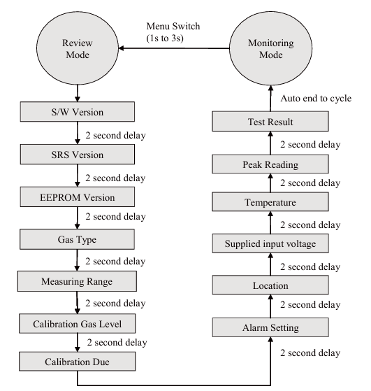
3. Operation and Configuration
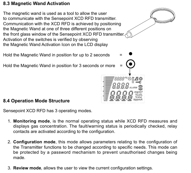
User interface: LCD display screen, displaying gas concentration, alarm status, fault codes, etc., operated through magnetic stick activation buttons.
Calibration: Calibration flow housing is required, clean air is used for zero calibration, and 50% LEL standard gas is used for range calibration. It is recommended to calibrate once every 6 months.
Installation and wiring
1. Installation requirements
Environmental conditions: Operating temperature -40 ° C to+65 ° C (transmitter), humidity 10-99% RH (non condensing), protection level IP66.
Sensor installation: Remote installation requires the use of a junction box (such as 2430-0021), with a cable length of ≤ 30 meters, and the sensor sintered surface facing downwards to ensure IPX6 protection.
Explosion proof requirements: Cable entrances must be equipped with sealed joints, with a distance of ≤ 18 inches (45cm) from the detector, and grounding must be connected at a single point to avoid loops.
2. Wiring specifications
Power supply: 16-32VDC (nominal 24VDC), power consumption ≤ 5W.
Cable selection: It is recommended to use shielded twisted pair cables with a cross-sectional area of 0.5-2.5mm ² (20-13 AWG). Remote sensor cables must comply with the AWM2464 standard.
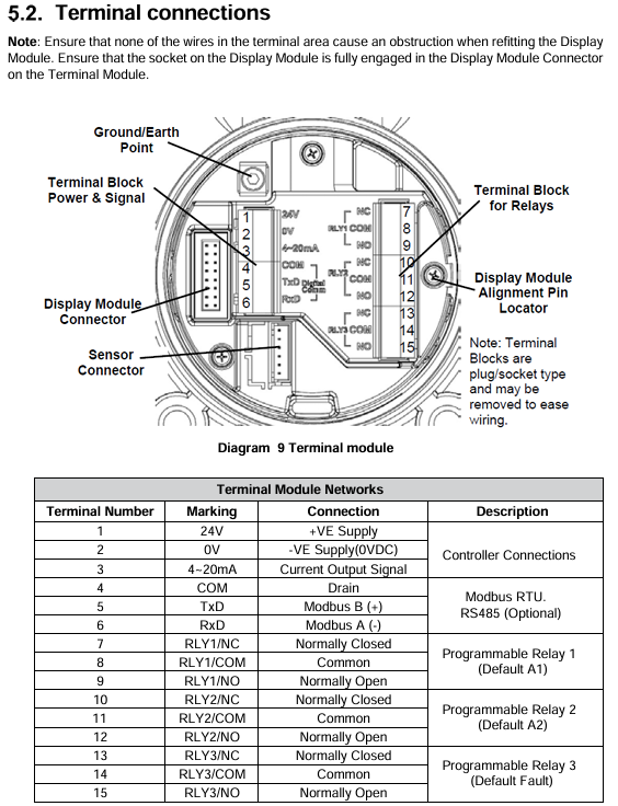
Terminal definition: including power supply, 4-20mA signal, relay, Modbus (optional), and sensor interface. Specific wiring needs to refer to the terminal table.
Calibration and maintenance
1. Calibration process
Zero point calibration: performed in clean air or using zero gas (such as compressed air).
Range calibration: Introduce 50% LEL standard gas and confirm the calibration value after stabilization.
Cross calibration: If using non target gas calibration, refer to the star rating table for adjustment (if using methane to calibrate ethylene, set the 62% LEL range).
2. Daily maintenance
Sensor replacement: Power off operation is required, and recalibration is required after replacement. The lifespan of the sensor is usually 36 months (affected by toxic substances such as silicone and sulfides in the environment).
Troubleshooting: By using fault codes (such as F02 indicating sensor failure and F03 indicating zero drift), common problems include wiring errors, power supply failures, and sensor malfunctions
Sensepoint XCD is a fixed gas detector suitable for hazardous areas such as Zone 1/2 and Class I Division 1/2. It can detect flammable gases, toxic gases, and oxygen, and achieve safety monitoring through 4-20mA signal output and programmable relays. It supports Modbus communication (optional), non-invasive operation (magnetic rod activation), and explosion-proof certification. It is widely used in industrial scenarios such as petroleum and chemical industries.
Core functions and technical features
1. Detection capability
Applicable gases:
Flammable gases: methane, propane, etc. (catalytic combustion or infrared technology).
Toxic gases: hydrogen sulfide (H ₂ S), carbon monoxide (CO), hydrogen (H ₂), nitrogen dioxide (NO ₂), etc. (electrochemical technology).
Oxygen (O ₂): Detection concentration range 0-25% Vol (electrochemical technology).
Accuracy: ± 1.5% LEL (flammable gas), ± 20% or specific value (toxic gas).
2. Output and Communication
Analog output: 4-20mA current signal (configurable as source or drain mode), output<1mA in case of fault, output 2mA or 4mA in suppression mode (17.4mA in oxygen version).
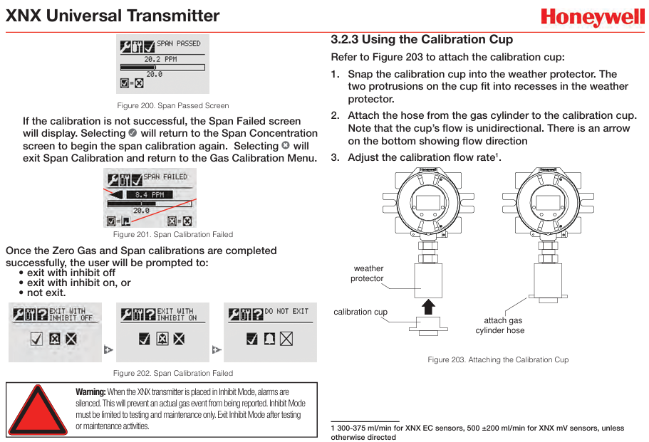
Calibration: A calibration cap (S3KCAL) is required, which supports zero and range calibration. It is recommended to perform it every 6 months.
Installation and wiring
1. Installation requirements
Environmental conditions: working temperature -40 ° C to+75 ° C, humidity 10-99% RH (non condensing), protection level IP66.
Installation position: Select according to the gas characteristics (such as lighter than air gas requiring a collection cone), and the sensor sintering surface should face downwards to ensure IPX6 protection.
Explosion proof requirements: Cable entrances must be equipped with sealed joints, with a distance of ≤ 18 inches (45cm) from the detector, and grounding must be connected at a single point to avoid loops.
2. Wiring specifications
Power supply: 12-32VDC (UL version) or 16-32VDC (ATEX/IECEx version), power consumption ≤ 5.5W.
Cable selection: It is recommended to use shielded twisted pair cables with a cross-sectional area of 0.5-2.5mm ² (20-13 AWG) and a maximum Modbus transmission distance of 1000 meters.
Terminal definition: including power supply, 4-20mA signal, relay, Modbus (optional) interface, specific wiring needs to refer to the terminal table.
Calibration and maintenance
1. Calibration process
Zero point calibration: performed in clean air or using zero gas (such as compressed air).
Range calibration: Introduce 50% of the full range standard gas and confirm the calibration value after stabilization.
Special requirement: The hydrogen sulfide sensor needs to be zeroed with compressed air to avoid the influence of humidity; Infrared sensors need to complete both zero and range calibration simultaneously.
2. Daily maintenance
Sensor replacement: Power off operation is required, and recalibration is needed after replacement. The lifespan of the sensor is usually 2-5 years (depending on the type).
Troubleshooting: By using fault codes (such as F02 indicating sensor failure and F03 indicating zero drift), common problems include wiring errors, power supply failures, sensor aging, etc.
Regular inspection: It is recommended to conduct a bump test every 6 months to ensure that the sensor responds properly
ATEX
ATEX/UKEX:
Certification numbers: UL 21 ATEX 2619X (transmitter), UL 21 ATEX 2620X (sensor head)
Protection level: II 2 GD Ex db IIC T6 Gb (-40 ° C to+65 ° C), Ex tb IIIC T85 ° C Db (-40 ° C to+65 ° C)
Additional requirement: Ensure static grounding to avoid sparks generated by friction.
IECEx:
Certification number: IECEx UL 21.0105X (transmitter), IECEx UL 21.0106X (sensor head)
Protection level: Ex db IIC T6 Gb (-40 ° C to+65 ° C), Ex tb IIIC T85 ° C Db (-40 ° C to+65 ° C).
UL/cUL:
Certification Number: E480011
Applicable area: Class I, Division 1/2(Groups B、C、D)、Class II, Division 1/2(Groups E、F、G)
Temperature range: -40 ° C to+65 ° C.
Performance and Security Certification
European standards:
EN 60079-29-1 (Flammable Gas Performance), EN 45544 (Toxic Gases), EN 50104 (Oxygen).
Other certifications:
Classification society certification (DNV, ABS, CCS, etc.), CE mark (compliant with EN 50270 electromagnetic compatibility standard).
Safety requirements: Installation must comply with local and national authoritative standards, and the complete “Sensepoint XRL User Manual” (available for download from Honeywell’s official website) must be read before operation.
Product version:
Analog (mA) output version: The terminals are defined as+24V DC/AC, 0V/24V AC, 4-20mA, and common terminal.
Modbus RTU output version: The terminal is defined as+24V DC/AC, 0V/24V AC, A (data+), B (data -).
Installation steps
Fixed detector: After determining the installation position, drill holes and fix the detector to the wall with suitable fasteners to avoid excessive tightening.
Cable connection:
Unscrew the front cover counterclockwise and smoothly pull out the main electronic module.
Remove the threaded protective sleeve and sealing components from the cable entrance, and install cable glands or conduits for the entrance in use.
Thread the cable through the glass, remove the terminal block and connect the wires according to the wiring diagram (wire size is 0.2-2.5mm ², it is recommended to use cold pressed terminals), and then reinstall the terminal block.
Grounding connection:
The internal grounding terminal is used to stabilize Modbus communication and resist RF interference, and the cable shielding layer needs to be single ended grounded (preferably at the controller end).
The external safety grounding terminal should be connected to the electrical safety ground to avoid grounding loops.
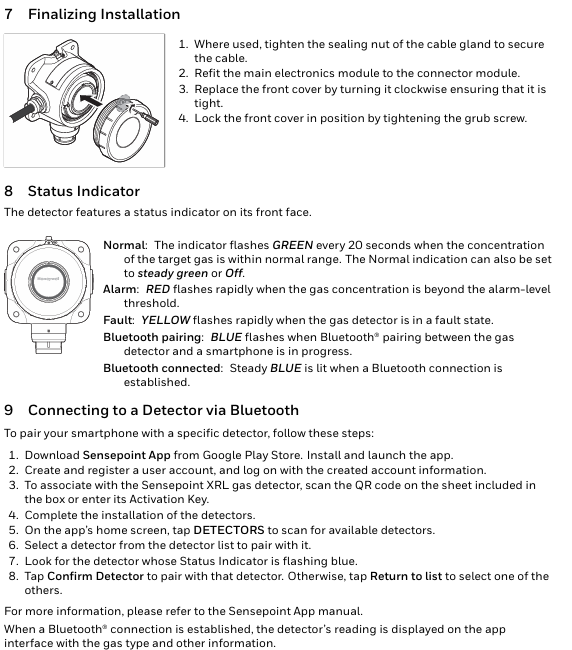
Complete installation: Tighten the sealing nut of the cable gland, reinstall the main electronic module and front cover, and tighten the grub screw to lock.
Status indication and Bluetooth connection
Meaning of status indicator light:
Normal: Blinks green every 20 seconds (can be set to stay on or off).
Alarm: Red flashing rapidly (gas concentration exceeds alarm threshold).
Download and install the Sensepoint app from the Google Play Store, register an account, and log in.
Scan the QR code inside the detector packaging box or enter the activation code to associate with the device.
On the homepage of the application, click on “Detectors” to scan for available devices, select the detector with a flashing blue status light, and click on “Confirm Detector” to complete the pairing.
XNX Universal Transmitter is a comprehensive gas detection system launched by Honeywell, suitable for hazardous locations. It can be combined with various sensor technologies such as catalytic beads, electrochemical (EC), or infrared (IR) to detect gas hazards such as toxic gases, flammable gases, and oxygen deficiency. It supports multiple communication protocols and has flexible installation and configuration methods, aiming to provide reliable gas monitoring solutions for industrial scenarios.
Core functions and technical features
Sensor compatibility
Supports catalytic bead sensors (for detecting flammable gases), electrochemical sensors (for detecting low concentration toxic gases), and infrared sensors (for detecting gases within the infrared spectral range).
Compatible with various specific sensors, such as MPD (Multi Purpose Detector), 705 series, Sensepoint series, Searchpoint Optima Plus, Searchline Excel, etc.
Communication function
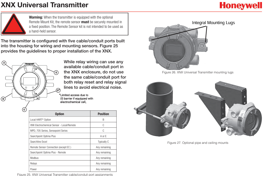
Standard communication: 4-20mA current loop HART digital communication, configurable as Sink, Source (3-wire system) or Isolated (4-wire system) electrical interfaces.
Optional communication interfaces: Relay (3 Form C contacts for alarm and fault indication), Modbus (supports RTU protocol, communicates through RS-485 physical layer), Foundation Fieldbus (digital communication system, supports multi device connection).
Operation and Configuration
User interface: Equipped with a custom backlit LCD display screen, non-invasive operation through magnetic wands, supporting 8 languages (English, Spanish, German, Italian, Portuguese, French, Russian, Chinese).
Menu functions: including configuration (language, date and time, sensor type, gas selection, etc.), testing (suppression, forced mA output, relay testing, etc.), information viewing (alarm/fault status, transmitter data, etc.), calibration, and other menus.
Security settings: Supports two-level password protection (Level 1 for daily maintenance and Level 2 for technical personnel and password management), requires resetting the factory default password to prevent unauthorized access.
Calibration and maintenance
Calibration types: including zero calibration, range calibration, functional gas testing (collision testing), mA output calibration, etc.
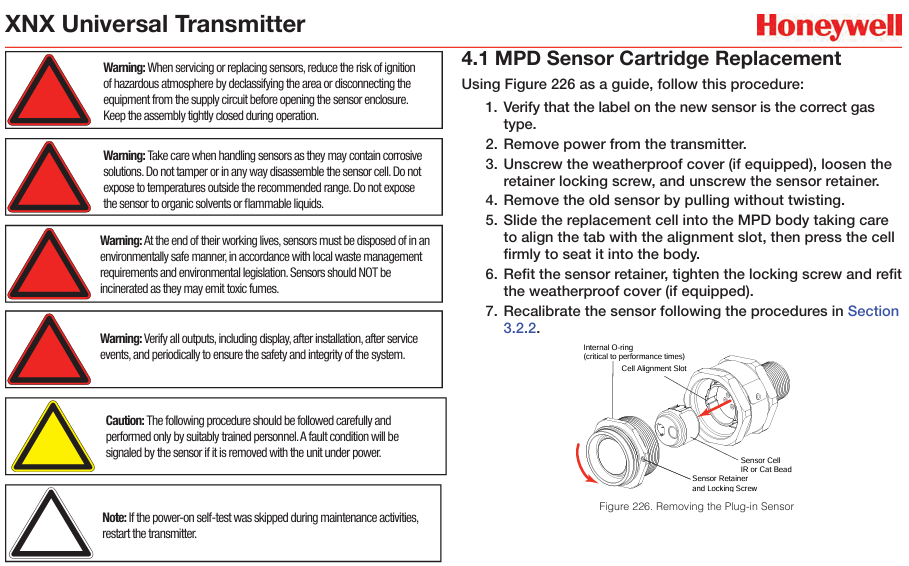
Sensor replacement: Detailed instructions on the replacement steps for MPD sensor cartridge and XNX EC sensor cartridge, which require recalibration after replacement.
Maintenance precautions: When handling sensors, attention should be paid to corrosion prevention, avoiding high temperatures and organic solvents, etc. Sensor scrapping must comply with environmental protection requirements.
Specification parameters
Electrical specifications
Working voltage: EC/mV type is 16-32VDC (nominal 24VDC), IR type is 18-32VDC (nominal 24VDC).
Power consumption: varies depending on the configuration, such as XNX EC with a maximum of 6.2W and XNX IR (Excel) with a maximum of 13.2W.
Output load: 4-20mA output. The total load resistance should be less than 500 Ω, with a minimum of 200 Ω.
Environmental specifications
Working temperature: -40 ° C to+65 ° C (-40 ° F to+149 ° F).
Size: 159 x 197 x 113.8 mm (6.138 x 7.75 x 4.48 inches).
Weight: Approximately 2.27kg (5lb) for aluminum alloy and 5kg (11lb) for stainless steel.
Warning and malfunction
Warning message: including power failure, abnormal temperature, calibration requirements, etc., detailing the applicable sensors, characteristics, and solutions for each warning.
Fault information: covering sensor faults, communication faults, internal faults, etc. Each fault has corresponding fault codes, characteristics, event history data, and solutions.
Information message: Record operation and status information such as forced relay mode startup, successful calibration, etc.
Certification and Warranty
Certification: Passed multiple certifications such as UL, CSA, FM, ATEX, IECEx, etc., suitable for different hazardous areas.
Warranty: XNX Universal Transmitter (excluding consumables) is covered by a 36 month warranty, XNX electrochemical sensor is covered by a 12 month warranty (from self commissioning or shipment, whichever comes first), and multi-purpose detector is covered by an 18 month warranty (from shipment).
Appendix Information
The HART protocol introduces the communication modes (point-to-point, multi station), wiring methods, device descriptor files, and operation menus of the HART interface.
Modbus protocol: describes the communication parameters, register definitions, and usage examples of the Modbus interface.
Control drawings: Wiring and installation drawings for different certified versions (UL/INMETRO, UL/CSA/FM, etc.) are provided.
This guide covers multiple industrial fixed gas and flame detection products under Honeywell, including various transmitters, detectors, controllers, and related accessories, suitable for gas leakage and flame monitoring in different industrial scenarios, aiming to provide safety assurance for industrial production.
Main product categories and characteristics
1. Explosion proof transmitter
XNX ™ Universal transmitter: supports multiple sensors, with modular input/output selection, integrated communication functions such as 4-20mA, HART, Modbus, etc., suitable for flexible integration and simple installation, and stable performance in harsh environments.
Sensepoint series: including Sensepoint XCD, Sensepoint XCD RTD, Sensepoint XCD RFD, etc., can detect flammable, toxic gases and oxygen. It adopts explosion-proof shell, supports 4-20mA and Modbus communication, and has the characteristics of non-invasive operation.
Series 3000 MkII and MkIII: Suitable for potentially explosive environments, supports remote sensor installation, and has advantages such as low power consumption and easy configuration.
2. Infrared transmitter
Searchpoint Optima Plus: Azardous area certified infrared combustible gas detector with fast response speed, high reliability, suitable for harsh environments, and insensitive to catalytic toxins.
Searchline Excel: Infrared open circuit combustible gas detector, available in short, medium, and long ranges, with a wide detection range and suitable for various industrial scenarios.
3. Flame detector
FSX series: including FS24X, FS20X, FS10, etc., using multispectral detection technology, can quickly detect flames and reduce false alarms, suitable for different hazardous areas.
SS series: such as SS4 series and SS2-AM series, with detection functions such as ultraviolet and infrared, suitable for various fire detection scenarios.
4. Gas detection controller
Touchpoint Pro: A modular flame/gas detection and control system that can be flexibly expanded, supporting multiple input/output modules and communication methods, suitable for centralized and distributed systems.
HA series: such as HA20, HA40, HA71, HA72, etc., can display and alarm multiple detection points simultaneously, with multiple communication and output functions.
5. Other products
RAEGuard 2 PID: Fixed photoionization detector for detecting volatile organic compounds (VOCs), easy to calibrate and maintain.
Midas ® Extractive Gas Detector: an extraction gas detector that can detect multiple gases and supports Ethernet power supply and multiple output modes.
SPM Flex: Based on Chemcassette ® The gas detector using tape technology can be used as a fixed and portable device, capable of detecting various sensitive gases.
Accessories and Services
Accessories: including calibration kits, power supplies, Horns&Strobes, mounting brackets, etc., to provide support for product installation, calibration, and operation.
Services: Honeywell provides installation, commissioning, calibration, maintenance, repair, and other services, with a global network of technical support resources that can provide 24/7 service (in the United States and Canada).
Product application
These products are widely used in various industries such as petroleum, chemical, power, warehousing, and automotive to monitor flammable and toxic gas leaks and flames, ensuring the safety of personnel and factories.
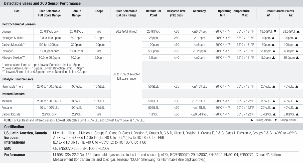
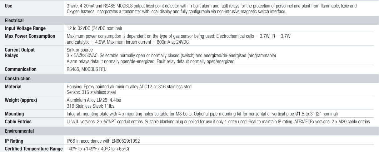
The Honeywell Sensepoint XCD is a fixed gas detector suitable for industrial applications, capable of detecting flammable gases, toxic gases, and oxygen. It has a 3-wire 4-20mA output and RS485 MODBUS communication function. It is equipped with built-in alarm and fault relays, a local display screen, and can be fully configured through a non-invasive magnetic switch interface to protect personnel and factories from related gas hazards.
Electrical specifications
Input voltage range: 12-32VDC (nominal 24VDC)
Maximum power consumption: Depending on the type of gas sensor used, the electrochemical cell is 3.7W, the infrared sensor is 3.7W, and the catalytic sensor is 4.9W; the maximum surge current at 24VDC is 800mA
Current output: can choose sinking or sourcing mode
Relays: 3, 5A@250VAC , can choose between normally open or normally closed (switch) and power on/off (programmable); Alarm relay defaults to normally on/off, fault relay defaults to normally on/on
Communication: RS485, MODBUS RTU
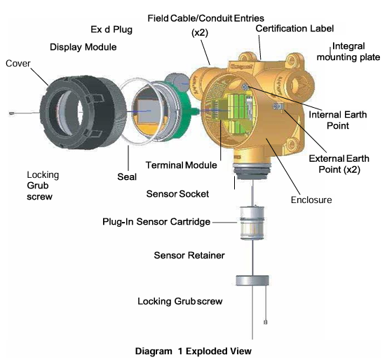
Structure specifications
Material: The shell is made of epoxy coated aluminum alloy ADC12 or 316 stainless steel; The sensor is made of 316 stainless steel
Installation: Integrated installation board with 4 mounting holes suitable for M8 bolts; Optional pipeline installation kit, suitable for horizontal or vertical pipelines (diameter 1.5-3 inches, nominal 2 inches)
Cable entry: UL/cUL version includes 2 3/4 inch NPT conduit entries, providing suitable plug closure (if only 1 entry is used), sealed to maintain IP rating; ATEX/IECEx version includes 2 M20 cable entry points
Environmental Specifications
IP rating: IP66 (compliant with EN60529:1992)
Certification temperature range: -40 º F to+149 º F (-40 º C to+65 º C)
Detectable gas and sensor performance
Gas type user selectable full-scale range default range user selectable step size default calibration point response time (T90) (seconds) accuracy working temperature range default alarm point A1 default alarm point A2
Authentication
United States, Latin America, Canada: UL/c-UL – Class I Zone 1 Groups B, C, D, Class I Zone 2 Groups B, C, D, Class II Zone 1 Groups E, F, G, Class II Zone 2 Groups F, G, -40 ° C to+65 ° C
European international: IEC Ex d IIC Gb T6 (ambient temperature -40 º C to+65 º C), Ex tb IIIC T85 ° C Db IP66; ATEX Ex II 2 GD Ex d IIC Gb T6 (ambient temperature -40 º C to+65 º C), Ex tb IIIC T85 ° C Db IP66
Performance: UL508; CSA 22.2 No.152 (flammable gases, excluding infrared sensors); ATEX,IEC/EN60079-29-1:2007,EN45544,EN50104,EN50271; China: PA type approval (transmitters and toxic gas sensors), “CCCF” Shenyang (flammable gas, approved by the fire department)
This manual introduces the hardware related content of the Woodward 723PLUS digital controller (models 9906-619, 9906-620, 9906-700), including general information, installation, control setpoint input, use of Servlink and Watch Window, product support and service options, etc. The controller is suitable for various application scenarios that require speed control.
General information
Application scenarios: It can adapt to various applications through programming. The hardware includes two speed inputs, supports two magneto electric sensors (MPUs) or proximity switches (such as for torsional filtering), as well as four analog inputs, three analog outputs, eight discrete inputs, and three discrete outputs, which can be used in load sharing systems. Its two LON channels can support related control functions.
Control options: Different models have different power input voltage requirements, and discrete input voltage provides switch command signals for control. There are also various other control options, such as proximity switch input suitable for low-frequency speed signals, 0-1mA output of instrument drivers, etc. The controller can be used in conjunction with proximity switches or magneto electric sensors with minimum frequency requirements.
Attachments: including handheld programmer (9907-205), SPM-A synchronizer, power output sensor, active power sensor, etc.
install
Scope: This includes general installation instructions for the 723PLUS controller, including power requirements, environmental precautions, location considerations, as well as unboxing, electrical connections, and installation inspection procedures.
Unpacking: Before handling the controller, it is necessary to read the relevant content on electrostatic discharge protection. When unpacking, be careful and check whether the controller is damaged. If there is any damage, immediately notify the shipper.
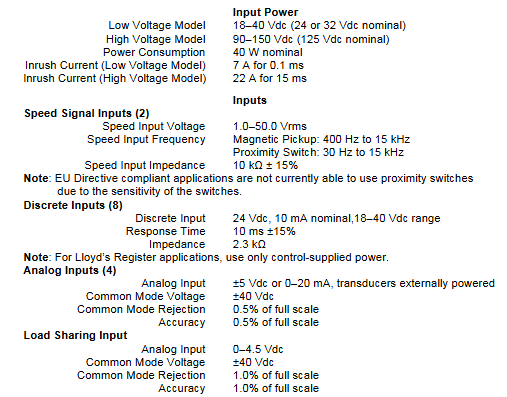
Power requirements: High voltage models require a 90-150Vdc voltage source, while low voltage models require an 18-40Vdc voltage source. To prevent damage to the controller, the input voltage range must not be exceeded. If battery power is used, an AC generator or other battery charging equipment must be equipped.
Location considerations: When selecting the installation location, factors such as ventilation, maintenance space, liquid and condensation prevention, electromagnetic interference prevention, and vibration prevention should be taken into account. The controller should not be installed on the prime mover, and the operating temperature range is -40 to+70 ° C (-40 to+158 ° F).
Specific installation requirements for marine use: The certification requirements for marine use types may change over time. In order to meet these requirements, all wiring, except for the part near the control connection terminal, must be inside metal conduits, and the control must be installed on a grounded metal mounting plate. It is also possible to meet attenuation requirements at specific installation locations or methods without additional special measures, but consultation with the shipyard is required.
Internal jumpers: The 723PLUS controller has ten two position internal jumpers located at the top of the printed circuit board. If you need to change the jumpers, you need to read the electrostatic discharge protection content first, power off and wait before operating. Different jumpers have different default settings and functions.
Electrical connection: External wiring connection and shielding requirements should refer to relevant software manuals. All shielded cables must be twisted pair, signal lines should be shielded, and shielding layer connections should follow specific requirements. It also provides detailed instructions on the connection methods and precautions for power supply, analog output, actuator output, speed signal input, load sharing line input, discrete input, analog input, etc.
Installation inspection program: After installation, visual inspection (checking linkage devices, wiring, terminals, speed sensors, etc.) and grounding inspection are required to ensure that the resistance between each terminal of the controller and the chassis meets the requirements.
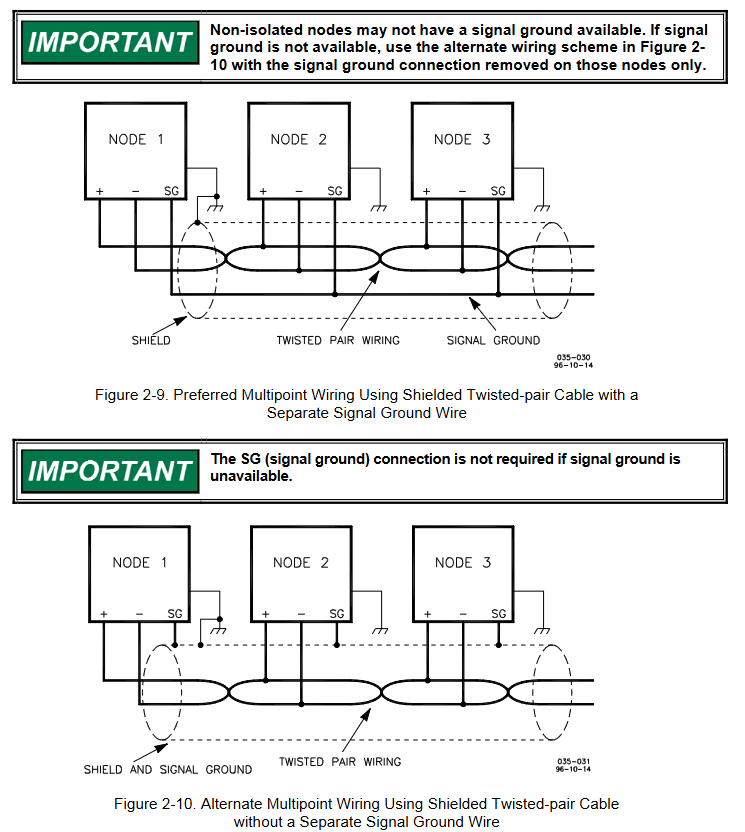
Serial port communication: The 723PLUS has two serial ports for communication, which can be configured into multiple types through software. When writing applications, it can be configured as a Modbus communication port and supports relevant protocols.
Terminal matching and grounding shielding: Different communication types (RS-422, RS-485) have different terminal matching requirements. RS-422 and RS-485 specifications require grounding wires when there are no other grounding paths between units. There are preferred and alternative wiring methods, and shielding and grounding must be handled correctly.
Control set point input
Overview: Due to differences in installation, system, and component tolerances, the 723PLUS controller must be adjusted for each system to achieve optimal performance. Setpoint inputs can be made through a handheld programmer or PC (using Watch Window software tools and Servlink software).
Handheld programmer and menu: The handheld programmer obtains power from the 723PLUS controller, connects to the RS-422 communication serial port of the controller, performs self check after power on, and displays application related information on the screen. The controller has a service menu and a configuration menu. The configuration menu needs to be entered when I/O is turned off (engine stopped), and the service menu can be directly entered through buttons. The operation menu and settings
Control set point input
Overview
Due to differences in installation environment, system, and component tolerances, the 723PLUS controller needs to be adjusted for specific systems to achieve optimal performance. Setpoint input can be completed through a handheld programmer or by connecting to a PC (using Watch Window software and Servlink software).
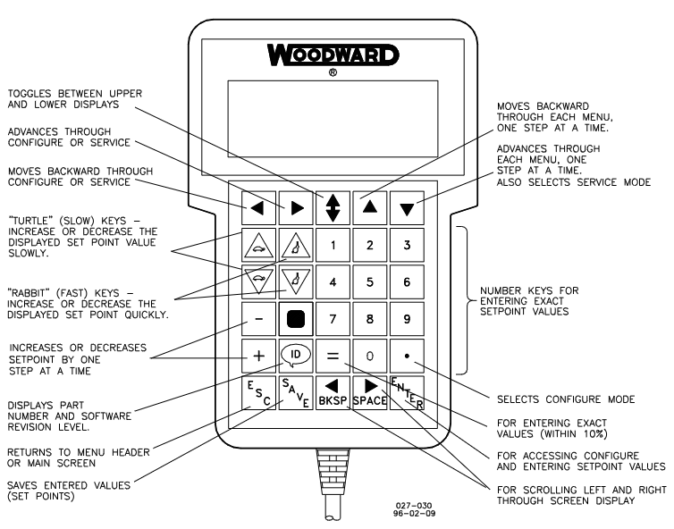
Handheld programmer and menu
Programmer connection and self-test
The handheld programmer (model 9907-205) obtains power from the 723PLUS controller and connects to the RS-422 communication serial port (J1 terminal) of the controller. When connecting, slightly loosen the right screw of the J1 port cover plate, rotate the cover plate clockwise to expose the 9-pin connector, and then firmly insert the programmer connector into J1.
After connecting the programmer to the controller, it will perform a power on self-test. After the self-test is completed, the screen will display two pieces of information related to the application. Press the ID key to switch between displaying the software’s part number and version letter.
Menu type and access
Configure menu: It needs to be accessed while the engine is stopped. Press the corresponding button, and the screen will display “To select configure, press enter”. After pressing the ENTER key, it will display “To shutdown I/O, press enter”. Press the ENTER key again to enter. If the engine is running during this process, it will shut down due to controller I/O shutdown.
Service menu: Press the DOWN ARROW key to access without shutting down the engine.
Menu Operation
Move between menus: Use the LEFT ARROW and RIGHT ARROW keys.
To move between set points within the menu: use the UP ARROW and DOWN ARROW keys.
Return to menu title: Press ESC key.
Exit menu: Press the ESC key, and the configuration menu will automatically save the set points when exiting.
Setpoint adjustment
Arrange mode
Use the TURTLE UP or RABBIT UP keys to increase the set value, and the TURTLE DOWN or RABBIT DOWN keys to decrease the set value. The adjustment rate of the RABBIT key is about 10 times that of the TURTLE key, which is suitable for situations where a large adjustment value is required.
For settings that require the selection of TRUE or False, use the corresponding increase or decrease keys.
Use the+or – keys to gradually change integer values in the application software.
To enter a precise value, press the=key, enter the desired value, and then press the ENTER key, but the value must be within 10% of the existing value.
Save Setpoints
At any time, the SAVE key can be used to save the set points and transfer the new set point values to the EEPROM memory, which retains all set points even when the controller is powered off.
To prevent the loss of set values after the controller is powered off due to the failure to save the set points, which may damage the engine, it is necessary to save the set points before removing the controller power supply.
This manual covers models 512/524 and 1712/1724 of Woodward EPG (Electrically Powered Governor) electric governors, including synchronous models, covering installation, operation, calibration, troubleshooting, and other content. It is suitable for speed control of diesel, gas, and gasoline engines as well as gas turbines.
General information
Application scenario: Used to control the speed of diesel, gas, gasoline engines and gas turbines, suitable for prime movers of mechanical loads and generator loads. Parallel generator sets require additional equipment and Woodward generator load sensors.
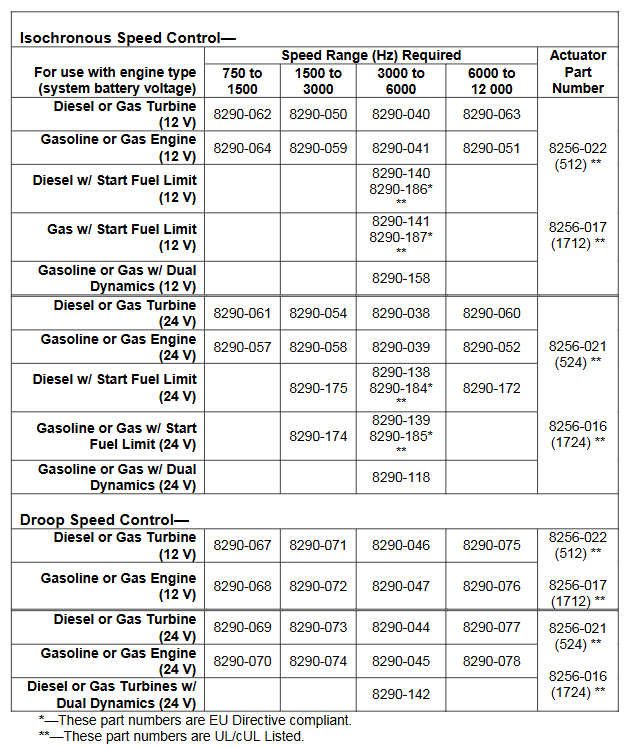
Model selection: 512/1712 models are used for 12V systems, and 524/1724 models are used for 24V systems. The speed controller has four frequency ranges for magnetic and electric sensors, suitable for different engine types. The actuator has a dual end output shaft that can rotate clockwise or counterclockwise to increase fuel consumption. You can also choose to activate functions such as fuel limit and dual dynamic characteristics, and select compatible speed controllers and actuators according to the model selection table.
Attachment: Includes generator load sensor (for parallel generator applications), ramp generator (for slowing down acceleration and deceleration), external capacitor (providing exponential ramp), etc.
Reference materials: Relevant publications can be obtained from authorized Woodward distributors or AISF, and can also be viewed on the Woodward website.
Installation, inspection, and calibration
Installation of speed controller: The working temperature range is -40 to+75 ° C (-40 to+167 ° F), and it should be installed in a location with adjustment and wiring space, avoiding exposure to radiant heat sources, close to actuators and batteries to meet wire length requirements, and ensuring good ventilation.
Installation of actuator and linkage device: The operating temperature range of the actuator is -40 to+93 ° C (-40 to+200 ° F), avoiding exposure to excessive heat sources. Suitable linkage devices need to be selected to match the rotation direction of the actuator and fuel control, ensuring that the linkage device moves flexibly, without friction or clearance. The actuator includes a reset spring, which does not require additional addition.
Installation of magneto electric sensor: Installed through the shell or rigid bracket, ensure that the detected gear is made of magnetic material, and the gap between the sensor and the outer diameter of the gear is about 1.0 millimeter (0.04 inch) at the closest point. The gap can be set in a specific way and the anti loosening nut can be tightened.
Wiring instructions: Use a specific wiring diagram for wiring, and use insulated terminals for all connections. The wiring to the actuator and battery should be as short as possible, and different models have different maximum wiring lengths. Fuses and switches or circuit breakers should be located in non grounded battery leads, and the connection between the battery and the speed controller terminal should come directly from the terminal, without passing through the distribution point. Attention should also be paid to the shielding layer connection and the installation of varistors required by EMC.
Installation inspection: including checking electrical connections, installation of magneto electric sensors, fastening of actuators and linkage devices, testing battery voltage, terminal voltage, preset rated speed and idle speed, adjusting gain and stability, setting starting fuel limits, etc. There are additional inspection steps for different application scenarios (such as applications with 2500 ramp generators and parallel generators).
Operate
The governor needs to be powered on at startup and powered off at shutdown (if the fuel control is in the minimum fuel position, power off will cause shutdown). The application of parallel generators requires synchronous and parallel operation. In droop mode, parallel operation requires adjusting the speed and fine tuning potentiometer to set the power generation. The EPG design is suitable for unmanned operation, and the idle rated switch can be controlled by multiple devices. When using the Woodward SPM synchronizer for parallel generator applications, equivalent automation operation can be achieved. The ramp generator can be used to provide adjustable speed change time between rated and idle.
Describe
Speed control application: The basic speed control components include magneto electric sensors, speed controllers, and actuators, with two control loops: speed loop and current loop. The speed loop controller compares the expected speed with the actual speed, calculates the error signal, and adjusts the gain and stability to customize the governor response; The current loop ensures the correct driving of the actuator, including relevant circuits and protection mechanisms.
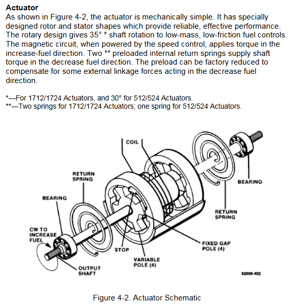
Executor: The mechanical structure is simple, with specially designed rotors and stators. The rotating design enables low-quality, low friction fuel control to achieve a certain angle of shaft rotation. When the magnetic circuit is energized, it provides torque in the direction of fuel increase, and the internal reset spring provides shaft torque in the direction of fuel decrease.
Application of using a ramp generator: slows down the speed change between idle and rated speed, without affecting steady-state speed, and controls the rate of change through acceleration and deceleration potentiometers.
Parallel generator application: Load sensors are used for synchronous or droop parallel connection. When isolating the bus, synchronous load distribution is usually selected. When parallel connected with infinite bus or incompatible electric speed controllers, droop operation is required.
Troubleshooting process
When there is a problem with the operation of the prime mover, it is necessary to first determine whether the fault is caused by the governor. The following methods can be used to troubleshoot:
Component replacement: Replace suspected faulty components with known normal ones.
System simplification: Gradually remove optional components and observe the performance changes after each removal.
Component testing: Test the output of suspected faulty components according to the manufacturer’s instructions or known input and operating conditions.
When testing EPG, you can refer to the installation inspection steps in Chapter 2, where using a signal generator with isolated output for rated speed preset is the best way to test EPG speed control capability. If it involves the application of parallel generators, it is also necessary to refer to the inspection content of load sensors in the 82313 manual mentioned in Chapter 2.
Other inspection items
Unstable speed or power output
If the prime mover remains stable at certain speeds or power outputs but oscillates in other situations, it may be due to incompatibility between the linkage device and fuel control. Please refer to the “Linkage Device Compatibility” section under “Installation of actuators and linkage devices” in Chapter 2.
If there is a low-frequency oscillation of about 1Hz in the prime mover and the gain and stability adjustments in Chapter 2 are correct, it may be due to friction in the linkage device. It is necessary to disconnect the actuator from the fuel control, manually operate the fuel control linkage device, check whether it moves flexibly without friction or clearance, and lubricate or replace components if necessary.
Unstable load distribution
Verify if the current transformers (CTs) and voltage transformers (PTs) of the load sensor are wired correctly.
Check if the droop or cross current compensation settings of the voltage regulator are correct, and if there are intermittent faults or other issues with the voltage regulator.
If the problem persists, the load gain can be appropriately reduced and the load gain potentiometers of all other load sensors in the system can be set to have the same load signal at full load. In extreme cases, the load signal may need to be reduced to 3 volts. In this case, authorized dealers or Woodward can be consulted.
Fuse or circuit breaker issues
If the fuse or circuit breaker disconnects after the prime mover is running, it may be due to high voltage spikes generated by the battery or battery charger. It is necessary to separately wire from the speed controller to the battery terminal as shown at the top of Figure 2-6.
If the fuse or circuit breaker is disconnected during initial startup, it may be a battery connection error. It is necessary to verify whether the battery connection is correct, remove the wires from terminals 1 to 4, and check whether each wire is short circuited to ground.
Differences in performance between hot and cold states
If the prime mover oscillates in the cold state and stabilizes in the hot state, the gain potentiometer can be slightly rotated counterclockwise. If stability needs to be maintained, the stability potentiometer can be slightly rotated clockwise.
This manual is the second volume of the Woodward 505 turbine digital controller, mainly covering service tools, peripheral devices, application notes, operator interface, service menu program, PID setting understanding, hardware/operating system faults, and multiple appendix contents. It aims to help users understand the application, configuration, operation, and fault handling of the controller.
Service Tools
Control Assistant (CA): The main service tool that can upload and download adjustable parameters, display real-time trends of any I/O signals or control parameters, troubleshoot system issues by viewing system software variables, and analyze any data log files collected from the controller.
Servlink to OPC Server (SOS): Integrated with Control Assistant, running as a service on PC, converting Woodward proprietary Servlink data from 505 to OPC data. The Control Assistant tool will connect to the SOS server as a client, and customers who want to link from 505 to OPC data also need to connect to SOS.
AppManager (AppMan): Used to transfer files to and download files from the controller. It can set the controller’s Ethernet port IP address and SNTP time synchronization IP address for network time protocol synchronization. It can also install software service package programs, start/stop control programs, or GUI programs.
Peripheral unit
DSLC-2 (Generator Synchronizer and Load Control): Connected to the 505 controller, it can be used to accurately detect the three-phase RMS generator output power and perform generator circuit breaker synchronization. It can also configure generator load distribution, reactive power or power factor control, process control, and basic load control functions.
VariStroke II (electro-hydraulic actuator): A linear electro-hydraulic actuator designed to provide linear driving force for steam turbine control valves or valve frames, which can be directly networked with the 505 controller to reduce system complexity and wiring requirements.
MFR300 (Multi functional Relay): A multifunctional generator protection relay used to detect and protect small generators, integrating all generator protection functions into a universal device to reduce overall system installation complexity and cost.
LS-5 (Protection/Circuit Breaker Control Relay): Integrated with generator circuit breaker synchronization, power detection, and protection functions, designed to be used in conjunction with prime mover controllers such as 505 to achieve precise generator control and provide the required generator protection.
Servo Position Controller (SPC): can be used to connect the 505 digital controller with existing valve operators or Woodward actuators, suitable for action integration or situations where it is directly incompatible with the 505.
Real Power Sensor: Used to detect the active power generated by the generator or the active power flowing through the interconnection line. Woodward manufactures two types of active power sensors, one that can only detect power flow in one direction and the other that can detect power flow from the bus to the interconnection line.
Engine Generator Control Package/Load Sharing (EGCP-3 LS): Based on microprocessors, it is suitable for three-phase AC generators equipped with Woodward speed controllers and automatic voltage regulators. It integrates functions such as synchronizers, load control, dead bus closure systems, reactive power/power factor control, process control, power and energy metering, and protective relays.
Application Notes
Overview: This article introduces the capabilities of the 505 digital controller and its application in the system. By demonstrating typical steam turbine applications and explaining their functions, it provides assistance for application programmers to configure the 505. It also explains how to apply control parameters or combinations not shown in the system.
Example applications: Contains various example applications, such as pump or compressor discharge pressure control and turbine inlet pressure limitation, inlet pressure control and automatic synchronization, and generator power limitation. Each example has corresponding configuration instructions and startup and operation mode instructions.
Operator Interface
Graphic display and key input: The service panel of the controller consists of hard key command buttons, soft key command buttons, and a graphical user interface screen. The system operator communicates with the 505 system through the service panel.
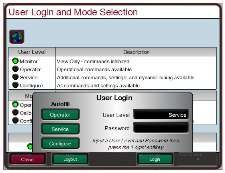
Service panel mode and user level: The 505 service panel has multiple modes (operation, calibration, configuration) and user levels (monitoring, operator, service, configuration). Different user levels determine the accessible and adjustable parameters and executable operations, and specific rules must be followed when adjusting values.
Service menu program
Overview: The service menu format of the 505 controller is easy to follow and can be used to customize the controller to better suit specific applications. Parameter adjustments in the service menu may affect system performance and should be handled with caution.
Service menu usage: As long as the controller is powered on, any user level can access the 505 service menu without shutting down the turbine. The permission to change these parameters is limited to the service user level and above, and requires entering the corresponding password for protection. Login to the service user level is required
CPC-II (Second Generation Current Pressure Converter) is an electro-hydraulic pressure regulating valve control device designed for positioning the servo mechanism of single acting steam turbine valves. Its extremely high precision and resolution make it very suitable for steam turbine valve control and related turbine speed and load control.
CPC receives a 4-20mA pressure demand signal and precisely controls the oil pressure to accurately locate the single acting steam turbine speed control valve. Accurate and stable steam valve control is directly related to improving the speed and load control of steam turbines, and reducing system mechanical wear.
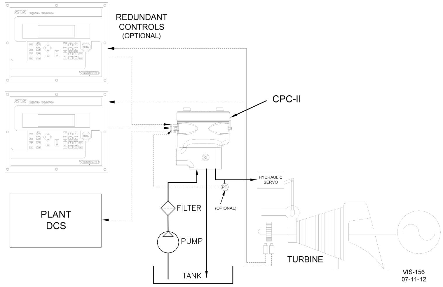
The redundancy feature of CPC makes it highly suitable for critical steam turbine applications, where the running time and availability of the turbine are crucial. It can be configured to accept redundant pressure demand inputs from one or two (redundant) controllers and track the inputs through voting. Alternatively, CPC can be configured to receive signals from its internal oil pressure sensors and external (redundant) oil pressure sensors, and use the voted health signal.
Its robust design (sturdy actuators, corrosion-resistant materials, single movable rotary valve, and self-cleaning port design) makes it ideal for challenging applications where dirty or contaminated oil may be present.
Optionally, two controllers can be connected to a single CPC in a redundant master/slave manner to allow the turbine to continue operating in the event of any control failure or the need for online changes. For applications that require complete redundancy, two CPCs can be optionally applied in a dual redundancy manner to simplify the entire system and control wiring.
Product description
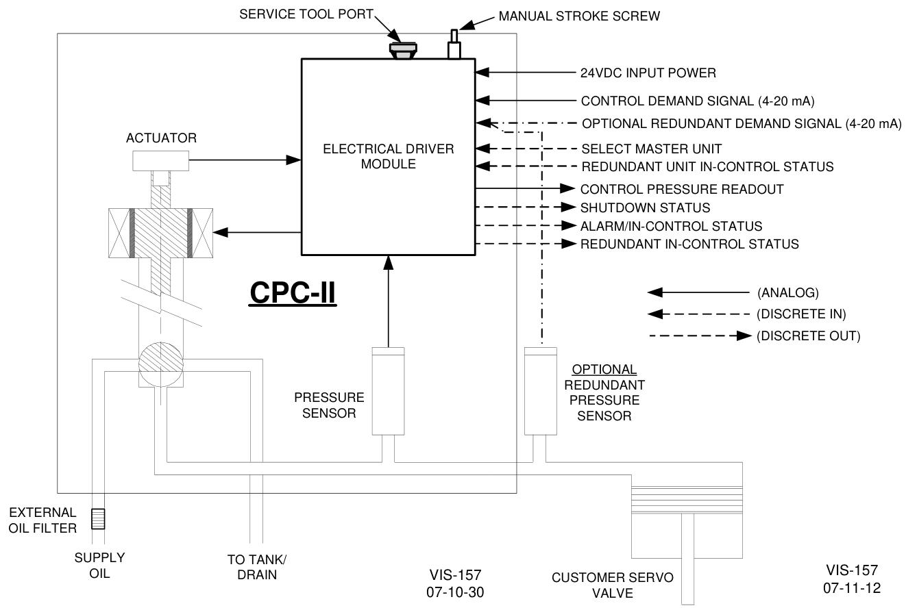
CPC is an electro-hydraulic pressure regulating valve control device that utilizes a highly accurate internal pressure sensor and PID controller to precisely control steam turbine valves. CPC consists of valve actuator components, pressure sensors, and electronic drive modules. The drive module of the device accepts one (or two) 4-20mA pressure set points and compares these set points with the detected oil pressure to accurately control the turbine valve oil pressure.
CPC controls oil pressure by delivering supply oil to its control oil output port (turbine valve control oil) or returning it to the system supply oil tank. The special PID architecture of this converter enables it to achieve very stable pressure control under normal conditions and respond to the required valve step changes with millisecond level response speed during system or factory transients. As a means of protecting the steam turbine, the internal valve reset spring forces the CPC into a fail safe position (connecting the oil port to the discharge port) and safely closes the turbine control valve in the event of any internal device failure (input power failure, pressure sensor failure, processor failure, etc.).
Main features
Resistant to oil pollution, precise fluid pressure control, stable and linear valve control, including valve linearization tables, redundant inputs/sensors for critical applications, receiving signals from redundant controllers, redundant (dual) CPC (master/slave) functions, standard installation and hydraulic connections, self-cleaning valve algorithms, status and health indicators, control pressure readings, software service tools with trend analysis, certified for hazardous locations in North America, compliant with applicable EU directives, certified for explosive environments by IECEx, certified for use within the EAC-CU range.
The manual stroke function allows users to manually adjust the CPC output pressure (turbine valve position) locally on the device through the internal manual stroke screw. This local manual stroke function is designed with built-in safety logic to prevent users from accidentally using this function during normal operation. Manual stroke function can also be achieved remotely or locally through CPC’s computer-based PCI tool.
Due to the non-linear flow rate of single-stage and staged inlet steam valves throughout their entire flow range, turbine control is typically detuned to compensate for unstable or sluggish control points throughout the entire range. In order to optimize turbine control, CPC includes an 11 point linearization table that allows turbine original equipment manufacturers or users to compensate for poor valve linearization through digital linearization control and valve flow relationship.
Due to the fact that many steam turbine users utilize redundant pressure converters to improve system reliability, and such applications are prone to sedimentation problems in the equipment, a special “Sill Buster” (patent application pending) program can also be configured to regularly remove internal sedimentation.
Specification parameters
Performance
Accuracy:<± 0.2% of full scale
Repeatability: 0.1% full scale
Temperature drift:<± 0.01% full-scale/° C
Pressure stability:<± 2% set point
Fault safe operation: When power is cut off or a fault is detected, the internal reset spring forces the control port oil to flow towards the discharge port
Configuration: Computer based service tool (RS-232 communication port)
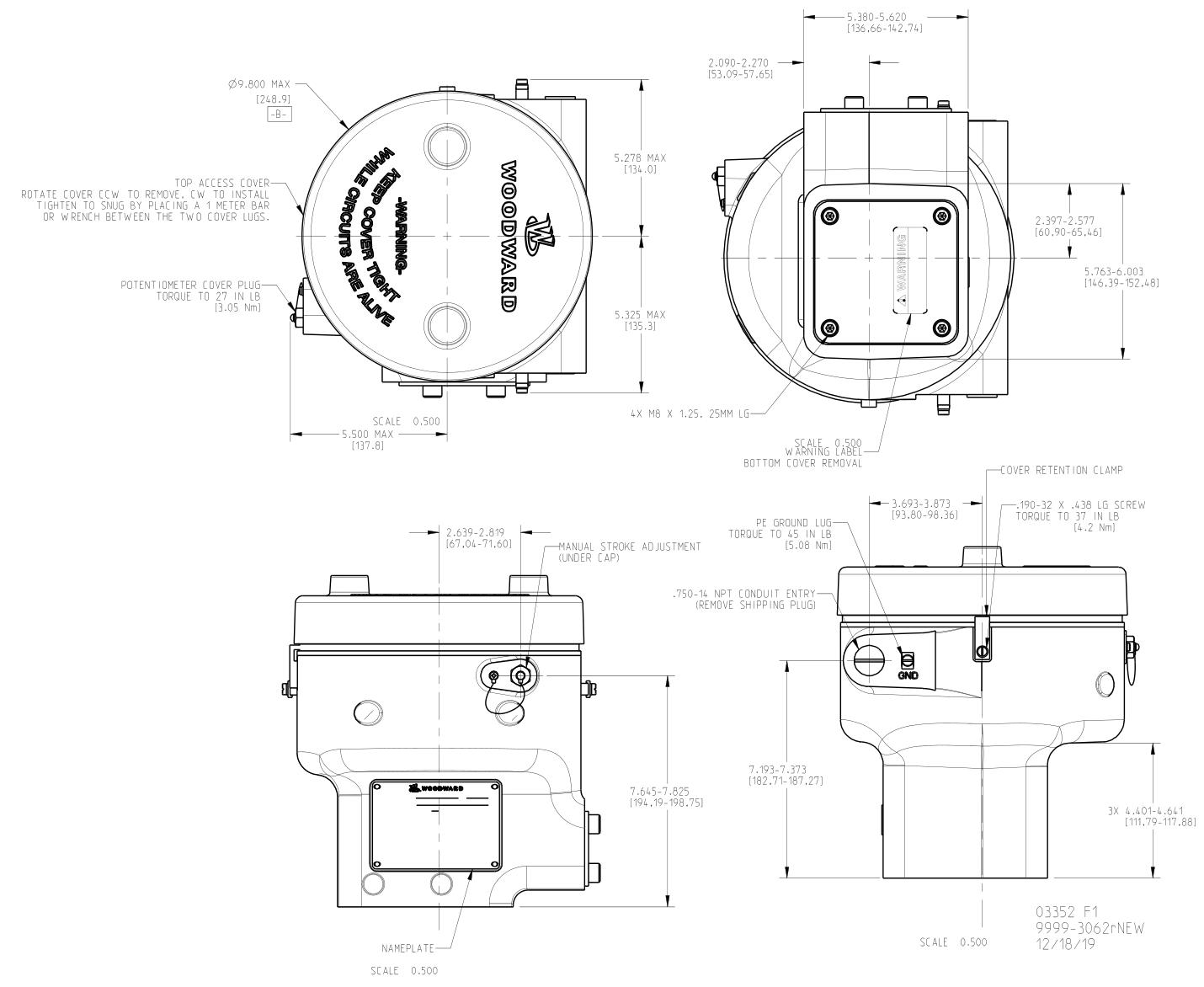
Physical parameters
Size: Refer to the outline drawing, the height x width x depth is approximately (290 x 270 x 270) mm