The Fire Sentry FS7 is a multispectral digital photoelectric radiation infrared fire and flame detector designed specifically for semiconductor cleanroom fire protection applications. It includes the FS7-2173 photoelectric radiation fire detector and the FS7-2173-2RP (modular model), the latter of which features multispectral WideBand IR ™、 Near band IR and visible light band fire detection function. Among them, FS-2173-2RP is independent, and FS-2173 is connected to the control module for use.
Core Features
Multispectral detection: using multispectral digital photoelectric radiation infrared technology, covering visible light, near band IR, and wideband IR detection ranges.
Two level fire detection response: Provide intelligent two-level response for semiconductor wet table fires. Level 1 (Alert): Respond to small fires with a heat output of 3kW (equivalent to a 100mm diameter polypropylene pool fire) and allow time for the fire to self extinguish; Second level (Alarm): If the fire does not self extinguish and expands to the 13kW thermal energy threshold specified by Factory Mutual (equivalent to a 200mm diameter polypropylene pool fire), the second level response is activated.
Anti interference capability: not affected by false alarm sources, not affected by absorbent smoke, gas or chemical vapor, insensitive to background radiation energy of electric heaters and ovens, capable of detecting hydrocarbon and non hydrocarbon fires.
Durable design: Adopting a sturdy leak proof, heat sealed, acid resistant injection molded polypropylene shell, with a wide field of view (120 °) and RS-485 interface for digital communication, FirePic ™ The function can record digital fire characteristics with time and date stamps, and the built-in detector has automatic self checking function. The modular model design can operate independently.
Application scenarios
Clean room open area
Wet table working surface
Wet platform underground space (ventilation room)
Pumps and equipment behind the wet table area
Underfloor area
IPA station (only for modular models)
Product model details
FS7-2173
It needs to be used in conjunction with the Fire Sentry FS7-130-SX controller or FSWB control panel. The controller and control panel provide power to the detectors, monitor the status of all detectors, and communicate with the detectors through a digital RS-485 communication channel.
Standard 6m (20ft) cable connector, connected to the controller or control panel through self-locking connector and Fire Sentry junction box, easy to install and reduces wiring problems.
Each detector can store up to 6 FirePics with time and date stamps in non-volatile memory ™ (Pre event multispectral sensor array data), the controller and control panel can also store event history tables in non-volatile memory, including warning, alarm, and fault history with time and date stamps. FirePics can be retrieved from the controller or control panel ™ And the history of events.
FS7-2173-2RP (modular model)
Equipped with discrete relay output, designed as an independent detector that can interface with any approved fire alarm panel.
The microprocessor is equipped with digital signal processing algorithms to continuously monitor the circuit, and the sensors have built-in self checks to verify normal operation.
Requires an external 24VDC power supply, comes with a standard 6m (20ft) tail cable, and can store up to 6 FirePics with time and date stamps in non-volatile memory ™ With 200 events, FirePics can be retrieved using the Fire Sentry FS7 interface suite and Windows based PC software ™ And the history of events.
Technical specifications
Project/Details
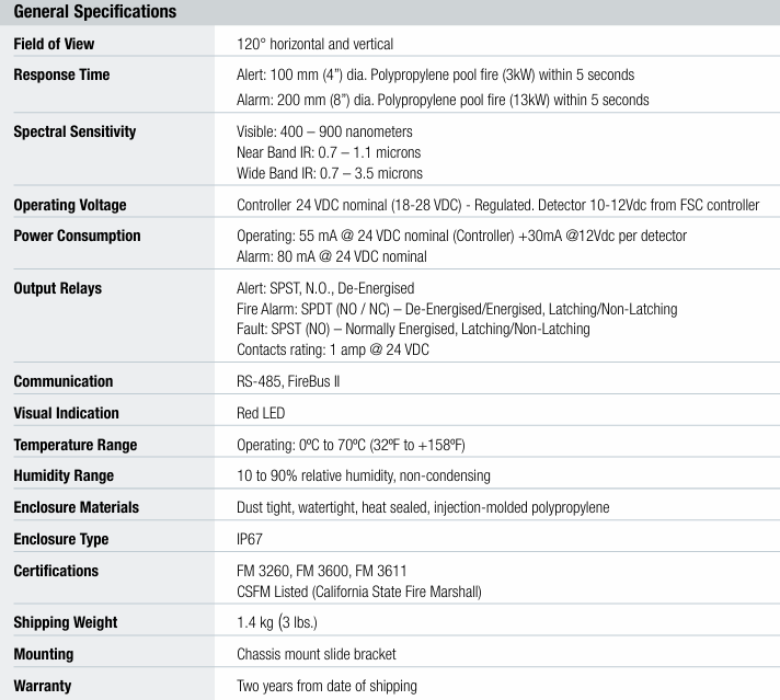
Field of view: 120 ° horizontally and vertically
Response time: Warning: For a 100mm (4-inch) diameter polypropylene pool fire (3kW), respond within 5 seconds; Alarm: Response within 5 seconds for 200mm (8 inches) diameter polypropylene pool fire (13kW)
Spectral sensitivity: visible light: 400-900 nanometers; Near band IR: 0.7-1.1 micrometers; Wide band IR: 0.7-3.5 microns
Working voltage: Controller: nominal 24VDC (18-28VDC) – stabilized voltage; Detector: 10-12VDC from FSC controller
Power consumption: Working: 55mA at 24VDC nominal (controller)+30mA at 12Vdc per detector; Alarm: 80mA at 24VDC nominal
Output relay: Warning: SPST, normally open, power off; Fire alarm: SPDT (normally open/normally closed) – power off/on, locked/unlocked; Fault: SPST (normally open) – normally powered on, locked/unlocked; Contact rating: 1 ampere at 24VDC
Communication: RS-485, FireBus II
Visual indication: Red LED
Temperature range: Operating: 0 º C to 70 º C (32 º F to+158 º F)
Humidity range: 10-90% relative humidity, no condensation
Fire Sentry FS System 10 ™ FS10-R is a fire detection/process control system designed specifically for automatic electrostatic powder spraying booth, belonging to multispectral digital photoelectric infrared fire detectors. It protects electrostatic powder spray booths worldwide, achieving millions of hours of safe operation and ensuring process safety 24/7.
Core Features
Multispectral detection: Using multispectral digital optoelectronic infrared technology, it has the ability to detect visible light, near-infrared, and wideband infrared.
Two level response mechanism: Unique two-level ALERT (warning) and FIRE ALARM (fire alarm) response, issuing a warning for gun “fireball” type fires first, and if the fire persists, issuing a fire alarm within 4-5 seconds.
Anti interference ability: not affected by false alarms caused by arc or corona discharge, insensitive to background radiation energy such as paint heaters, not affected by smoke absorption or paint solvent mist in liquid paint spraying booth, able to detect paint, powder or oil residue through the detector lens.
Intelligent function: Built in automatic “through the lens” self-test function, equipped with RS-485 interface for digital communication, FirePic ™ Retrievable pre fire data records, SnapShot ™ It can dynamically display the content detected by the detector in graphics.
Application scenario (indoor use only)
Liquid paint spraying line
Aerosol filling
Powder coating booth
Curing Oven
Product Details
Fire Sentry FS System 10 ™
Design purpose: Designed specifically for liquid and powder coating applications, it is a high-speed detection solution with process control capabilities. It can quickly detect flames, initiate the shutdown of the electrostatic coating process within milliseconds, and prevent the spread of fire.
Controller configuration: There are two configurations: wall mounted controller and card type controller. The wall mounted controller is an independent system installed in a NEMA 12 enclosure with an LCD display and LED status lights, and includes three 10 ampere mechanical relays for turning off paint flow, static electricity, and conveyor belts.
Data storage and communication: The detector reports real-time event history and fire technology data, stored in the non-volatile memory of the controller, FirePic ™ And SnapShot ™ Data can be downloaded from the RS-232 port of the controller via a PC, and each controller can be connected to 1 or 2 detectors.
Fire Sentry FS10-R Unitised
Design Basis: Based on Fire Sentry FS System 10 ™ Design with independent operational capability.
Performance features: Its WideBand IR ™、 Near band IR and visible light sensors combined with advanced signal processing provide optimal performance, high-speed fire response, and optional factory sensitivity settings and alarm outputs, providing an enhanced fire detection and safety solution for the coating industry.
Interface method: Designed to be used in conjunction with any approved fire alarm panel, the interface with the fire alarm panel is achieved through ALARM, ALERT, and FAULT relays of the detector.
Technical specifications
FS10 wall mounted controller specifications
Shell: NEMA 12 painted steel shell with welded seams, door gasket, key lock.
Display and indicator: 4 status LEDs (fault, fire early warning, warning, alarm), 1 LCD display screen.
Input power supply: There are different options such as 120VAC and 240VAC, allowing for ± 10% fluctuation.
Power consumption: The 120VAC option is rated at 0.22 amperes (25 watts), while the 240VAC option is rated at 0.11 amperes (25 watts).
Output signal relay: including fire early warning, warning, fire alarm, fault and other relays, with a rated contact value of 1 ampere at 24VDC.
Process shutdown relays: 3 SPDT relays with contact ratings of 10 amperes at 120VAC.
FirePic ™: There are a total of 6, each lasting 8 seconds.
Detector (FS10 related) specifications
Sensitivity: 4.57 meters (15 feet).
Response time: 0.3 seconds for warning (for “fireball” type fires), 0.5 seconds for early warning of fires, and 4 seconds for fire alarm (if the fire persists).
Field of view: 90 ° (horizontal and vertical ± 45 °).
Weight (aluminum): 1.7 kilograms (3.8 pounds).
Working temperature: -40 º to+85 º C (-40 º to+185 º F).
Shell: Copper free powder coated aluminum or optional 316 stainless steel, compliant with NEMA 3, 4, and 4X standards.
Certification: Explosion proof; Class I, Zone 1 and Zone 2, Groups B, C, and D; Class II, Zone 1 and Zone 2, Groups E, F, and G; Class III; FM and CE certification.
Spectral sensitivity: visible light 400-700 nanometers, near band IR 0.7-1.1 micrometers, wide band IR 0.7-3 micrometers.
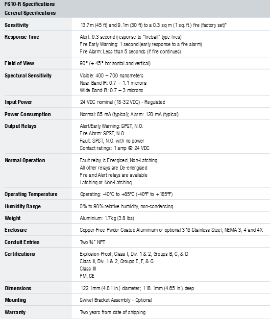
Sensitivity: For a 0.3 square meter (1 square foot) fire, the factory sets it to 13.7 meters (45 feet) and 9.1 meters (30 feet) * (note: detectors set to 13.7 meters (45 feet) sensitivity have no warning/fire early warning output).
Response time: 0.3 seconds for warning (for “fireball” type fires), 1 second for early fire warning, and less than 5 seconds for fire alarm (if the fire persists).
Field of view: 90 ° (horizontal and vertical ± 45 °).
Input power supply: nominal 24VDC (18-32VDC) – regulated.
Power consumption: Normal 85mAh (typical value), alarm 120mAh (typical value).
Output relay: SPST for warning/early warning, normally open; The fire alarm is SPST, normally open; The fault is SPST, constantly open without power supply, with a rated contact value of 1 ampere at 24VDC.
Normal operation: The faulty relay is powered on and not locked; All other relays are powered off; Fire and warning relays can be selected to be locked or non locked.
Working temperature: -40 º C to+85 º C (-40 º F to+185 º F).
Humidity range: 0% to 90% relative humidity, no condensation.
FS10 Card Controller Specification
Shell: NEMA 1 steel shell.
Indicator: 4 status LEDs, corresponding to normal operation, warning, fire early warning (FEW), fire alarm, and fault status.
Input power supply: 24V DC (+10/-15%).
Power consumption: 65 milliamps, nominal 1.6 watts.
Output signal relay: There are multiple models, and different models have different relay configurations.
FirePic ™: There are a total of 6, each lasting 8 seconds.
FS20X is the latest generation of high-tech multispectral (UV/dual IR/VIS) fire and flame detectors, belonging to the FSX series of advanced technology photoelectric flame detectors. It is based on the highly successful and reliable SS4 detector development, achieving a huge leap in integrating infrared and ultraviolet sensing technologies, and has a validated ultraviolet sun blind sensor. Compared with traditional UV/IR detectors, FS20X responds faster to fires over a wider temperature range without false alarms, and has a longer detection range.
Core Features
Advanced sensing technology: using patented WideBand IR ™ The combination of infrared technology and ultraviolet technology, equipped with visible light sensors to optimize false alarm elimination, and a validated ultraviolet sun blind sensor.
Performance parameters: Detection range exceeding 60 meters (200 feet) (for a 0.1 square meter (1 square foot) heptane reference flame under extremely high sensitivity settings), field of view at a 90 ° horizontal cone (off-axis ± 45 °), selectable detection sensitivity (extremely high (60 meters), high (45 meters), medium (30 meters), low (15 meters)).
Intelligent function: Dual microprocessors ensure high-level fault safe operation and fast and reliable performance; Equipped with a real-time clock that can accurately record event times; FirePic ™ Can store up to 6 pre fire event data; Event logs can record up to 200 events with dates and timestamps.
Communication and output: Built in RS-485 ModBus communication function, non isolated 4-20mA analog output (sink or source), with alarm, fault, and fire verification relays.
Other features: automatic optical path and electronic self-test; The patented electronic module is used for component protection and adopts plug-in termination for easy on-site installation; There are two 25mm conduit inlets or two three-quarters “NPT inlets; Low power consumption, high resistance to radio frequency interference and electromagnetic interference; Obtained multiple certifications such as FM, ATEX/IECEx, INMETRO, CU-TR, etc., meeting SIL 2 requirements, optional certification to EN54-10:2002, with FM 3260 performance.
Advantages and Applications
advantage
Capable of detecting hydrocarbon and non hydrocarbon fuel fires under all environmental conditions, with a wide operating temperature range, unaffected by arc welding, and good false alarm elimination effect.
Low maintenance, stable operation, fault diagnosis, real-time graphics (RTGs) display, and FirePics download can be performed through PC software and interface module (FSIM) ™ And event logs, suitable for various application scenarios.
Application scenarios: including refineries and oil production facilities, offshore platforms, turbine/compressor casings, acetylene processing and storage facilities, oil and gas pipelines and pumping stations, LNG/LPG loading and unloading facilities, natural gas and CNG plants, ethanol, methanol and IPA production and storage facilities, crude oil and gasoline storage and oil depots, aircraft hangars, hydrogen plants and storage facilities, paint and solvent storage facilities, chemical production, storage and loading and unloading facilities, power plants, silane gas storage facilities, etc.
Technical specifications
Project, details
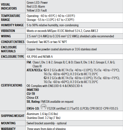
Response time: 3-5 seconds for a 0.1 square meter (1 square foot) n-heptane flame at a distance of 30 meters (100 feet); Response time of 3-10 seconds for a 0.1 square meter (1 square foot) n-heptane flame at a distance of 60 meters (200 feet)
Spectral sensitivity: UV: 185-260 nanometers; Visible light: 400-700 nanometers; Near band infrared: 0.7-1.1 micrometers; Wide band infrared: 1.1-3.5 microns
Working voltage: nominal 24 Vdc (18-32 Vdc) – stabilized voltage
Power consumption operation: 85 mA at 24 Vdc nominal; alarm: 135 mA at 24 Vdc nominal; heater: additional 155 mA (note: heater turns on at -17 º C (0 º F))
Output relay: Fire alarm: SPDT (NO/NC) – power-off/power on, locked/non locked; Fault: SPST (NO) – Power off/on, locked/unlocked; Auxiliary: SPDT (NO/NC) – power-off/power on, locked/unlocked; Contact rating: 1 ampere at 24 Vdc
Analog output: 0-20 mA stepped – source or sink can be selected by the user
Loop resistance 50-400 ohms
Communication: One of the following can be selected by the user: RS-485, ModBus protocol; RS-485,FireBus II; RS-485 dedicated (optional); HART, Optional plugin module (not applicable to EN54-10 devices)
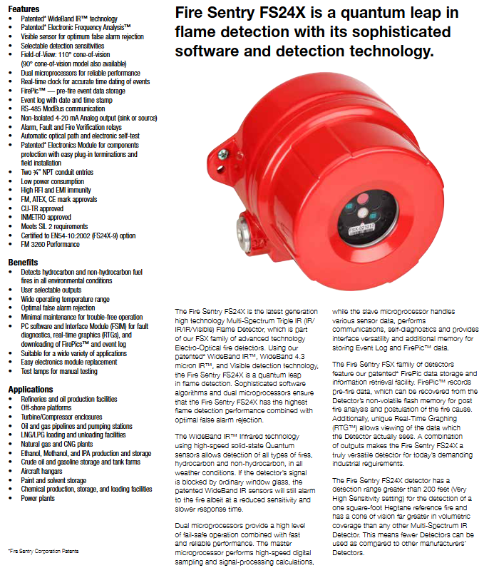
Visual indicator: Green LED: Power supply; Red LED: Alarm; Yellow LED: Fault
Temperature range: Operating: -40 to+85 º C (-40 to+185 º F); Storage: -55 to+110 º C (-67 to+230 º F)
Humidity range: 5-98% relative humidity, no condensation
Vibration: reaching or exceeding MilSpec 810C method 514.2, curve AW12
Wiring: 2.5 mm ² (14 AWG) to 0.326 mm ² (22 AWG); Recommend using shielded cables
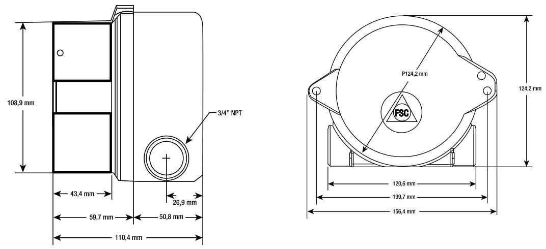
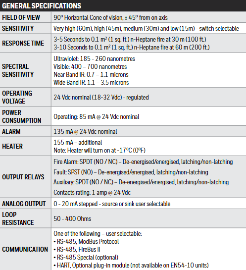
Conduit inlet: Standard: Two M25 or two three-quarters “NPT
Certification: FM, ATEX/IECEx, INMETRO, CU-TR, China EX and other certifications, SIL rating: FMEDA can be provided upon request, FS20X certification is 1175a/01 (LPCB), CPR 0832-CPR-F0515
Transportation weight: Aluminum: 1.6 kg (3.6 lbs); Stainless steel: 3.2 kg (7 lbs)
The Fire Sentry FS24X is the latest generation of high-tech multispectral triple infrared (IR/IR/IR/visible light) flame detector, belonging to the FSX series of advanced technology photoelectric fire detectors. It adopts patented WideBand IR ™、 WideBand 4.3-micron IR ™ Visible light detection technology has achieved a huge leap in flame detection. The complex software algorithms and dual microprocessors ensure the highest flame detection performance while optimally eliminating false alarms.
Core Features
Patent technology: WideBand IR with patented technology ™ Technology Electronic Frequency Analysis ™ The technology and Electronics Module technology used to protect components have improved detection performance and reliability.
Detection capability: Visible light sensors help optimize false alarm elimination; Selectable detection sensitivity; The field of view has a 110 ° cone of view (there are also 90 ° cone models).
Performance guarantee: Dual microprocessors ensure reliable performance; Real time clock can accurately record event time; FirePic ™ Capable of storing pre fire event data; The event log has a date and timestamp.
Communication and output: equipped with RS-485 ModBus communication function; Non isolated 4-20mA analog output (sink or source); There are alarm, fault, and fire verification relays.
Other features: automatic optical path and electronic self-test; Easy plug-in termination and on-site installation; Two inlet ports for 3/4 “NPT conduits; Low power consumption; High resistance to radio frequency interference and electromagnetic interference; Obtained multiple certifications such as FM, ATEX, CE mark, etc., meeting SIL 2 requirements. FS24X-9 option has passed EN54-10:2002 certification and has FM 3260 performance.
Advantages and Applications
advantage
Capable of detecting hydrocarbon and non hydrocarbon fuel fires under all environmental conditions.
Users can choose the output method; Wide working temperature range; The false positive elimination effect is good.
Low maintenance and stable operation; Fault diagnosis, real-time graphics (RTGs) display, and FirePics download can be performed through PC software and interface module (FSIM) ™ And event logs.
Suitable for various application scenarios; Easy replacement of electronic modules; There are test lights available for manual testing.
Application scenarios: including refineries and oil production facilities, offshore platforms, turbine/compressor casings, oil and gas pipelines and pumping stations, LNG/LPG loading and unloading facilities, natural gas and CNG factories, ethanol, methanol, and IPA production and storage facilities, crude oil and gasoline storage and oil depots, aircraft hangars, paint and solvent storage facilities, chemical production, storage, and loading and unloading facilities, power plants, etc.
Technical specifications
Project/Details
Field of view: FS24X-9: 90 ° cone, off-axis ± 45 °; FS24X-2: 110 ° cone, off-axis ± 55 °
Sensitivity: switchable options: extremely high (200 feet), high (150 feet), medium (100 feet), low (50 feet)
Response time: 3-5 seconds for a 1 square foot n-heptane flame at a distance of 30 meters (100 feet); Response time of 3-10 seconds for a 1 square foot n-heptane flame at a distance of 60 meters (200 feet)
Spectral sensitivity: visible light: 400-700 nanometers; Near band infrared: 0.7-1.1 micrometers; Broadband infrared: 1.1-3.0 microns, 3.0-5.0 microns
Working voltage: nominal 24 Vdc (18-32 Vdc) – stabilized voltage
Power consumption operation: 56 mA at 24 Vdc nominal; alarm: 106 mA at 24 Vdc nominal; heater: additional 155 mA (note: heater turns on at 0 º F (-17 º C))
Output relay: Fire alarm: SPDT (NO/NC) – power-off/power on, locked/non locked; Fault: SPST (NO) – Power off, locked/unlocked; Auxiliary: SPDT (NO/NC) – power-off/power on, locked/unlocked; Contact rating: 1 ampere at 24 Vdc
Analog output: 0-20 mA stepped – source or sink can be selected by the user
Loop resistance: 50-400 ohms
Communication: One of the following can be selected by the user: RS-485, ModBus protocol; RS-485,FireBus II; HART, Optional plugin module (not applicable to EN54-10 devices)
Visual indication: Green LED: Power supply; Red LED: Alarm; Yellow LED: Fault
Temperature range: Operation: 110 ° Field of view FS24X: -40 º F to+185 º F (-40 º C to+85 º C); 90 ° field of view FS24X: -60 ° C to+85 ° C (-76 ° F to+185 ° F); Storage: -67 º F to+230 º F (-55 º C to+110 º C)
Humidity range: 5-98% relative humidity, no condensation
Vibration: reaching or exceeding MilSpec 810C method 514.2, curve AW12
Wiring: 14 AWG to 22 AWG; Recommend using shielded cables
Conduit inlet: Standard: Two M25 or two three-quarters “NPT
Certification: FM, ATEX/IECEx, INMETRO, CU-TR and other certifications, SIL rating: FMEDA can be provided upon request, FS24X-9 certification is 1175a/02 (LPCB), CPR 0832-CPR-F0516
Transportation weight: Aluminum: 1.6 kg (3.6 lbs); Stainless steel: 3.2 kg (7 lbs)
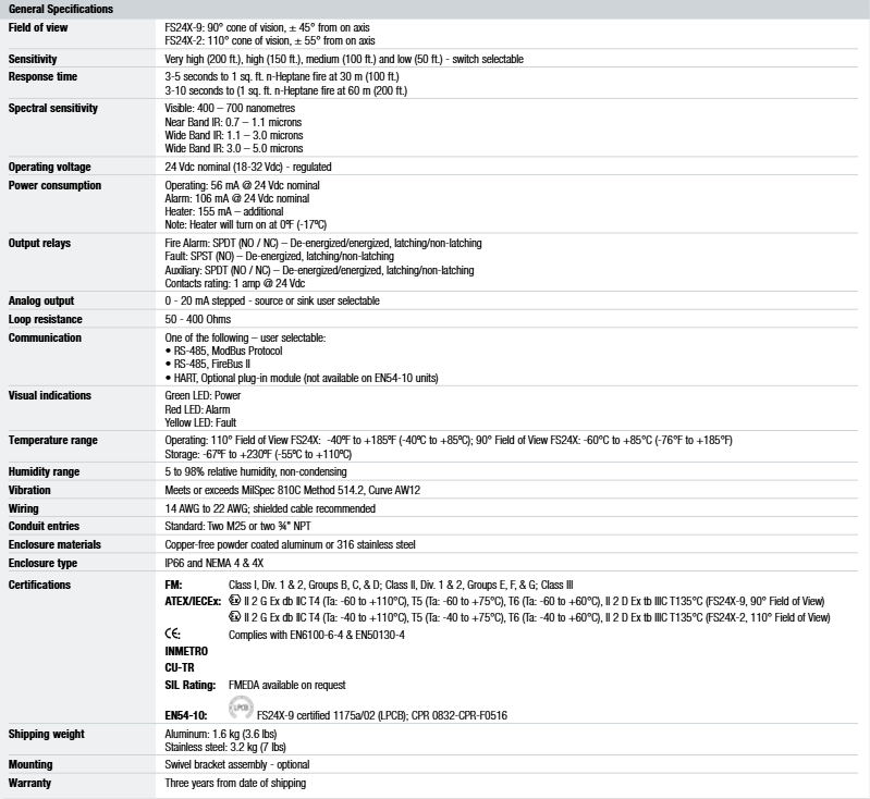
Searchline Excel Cross Direct is developed based on mature open circuit design, specifically designed to meet the monitoring needs inside HVAC ducts and turbine casings. It is a reliable infrared open circuit gas detector suitable for ducts. It can provide the highest response speed with a low alarm set point over a wide temperature range, complementing other system gas protection devices such as toxic gas detection, and providing fast and effective protection for gas entering ventilation ducts.
Application scenarios and core advantages
Application scenarios: including control rooms, personal shelters, turbine casings, etc.
Core advantages:
Fast response speed, able to provide early warning; High sensitivity, allowing for setting low alarm points.
The design that does not require alignment makes installation simple; Strong tolerance to pipeline bending and vibration, ensuring continuous operation of the system.
Built in functional gas testing device for easy system inspection; Anti pollution optical components reduce unplanned maintenance needs.
Not affected by catalytic toxins, it can work in an inert environment.
Technical specifications
Project/Details
Detectable gas calibration: methane (a gas mixture with methane as the main component (>70%) and the rest as C ₂ – C ₆ hydrocarbons)*
Detection range: 0-100% LEL
Minimum alarm threshold: 20% LEL (pipeline width>0.5 to 2.5m); 10% LEL (pipeline width>2.5 to 5m)
Response speed: T90<1 second
Output signal: Over range: 21mA; Warning: 3mA; Beam blocking: 2.5mA; Suppression: 2mA; Fault: 0mA; RS485 serial link
Digital output: Modbus RS485 multipoint (using DX100 (M) or XNX universal transmitter with Modbus option)
Working temperature: Environmental temperature: -40 ° C to+50 ° C (-40 ° F to 122 ° F); The maximum internal temperature of the pipeline can reach 60 ° C (140 ° F), but the external ambient temperature of the transmitter and receiver units must be within the working range; For high-temperature applications, please contact Honeywell Analytics
Working humidity: 0-99% (no condensation)
Work pressure: 91.5-105.5 kPa (without compensation)
Power supply equipment: 18 to 32V DC; Heating reflector: 18 to 28V DC
Power consumption device: maximum 13W; heating reflector: rated as 6W at 24VDC
Shell material: 316 stainless steel
IP rating: IP66 and IP67
Weight: transceiver 13kg; reflector plate: 5kg (pipe width>0.5m to 2.5m), 10kg (pipe width>2.5 to 5.0m)
EMC standard: EN50270
Safety certification: ATEX, IECEx, UL and other certifications, specific certification information may vary depending on the components such as transmitter, receiver, heating plate, etc
Communication and installation related
Communication function: Can be combined with XNX universal transmitter kit, standard equipped with local HART ® Ports and HART via 4-20mA ®, Can be accessed through the XNX user interface or compatible HART ® Configure with handheld interrogator; In permitted applications, the SHC-1 handheld interrogator and SHC-1 protective device module can be used for invasive connections. The multi-point Modbus function can save installation and wiring costs, and the bidirectional digital communication protocol allows configuration, warning, and fault diagnosis information to be transmitted back to the control room, reducing maintenance costs.
Installation composition: The path range is 0.5m-5m, mainly including heated retroreflector, installation plate, installation unit, transmitter, receiver, conduit, junction box, etc.
Searchline Excel is the world’s best-selling infrared open circuit gas detector, with over 25000 units installed in various challenging industrial applications. From the Arctic Circle to the deserts of the Middle East, it has always been the preferred product for customers and has become a standard configuration in the oil, gas, and petrochemical industries, meeting their demanding needs.
Application scenarios: including offshore platforms and vessels (FPSOs), downstream chemical processing plants, natural gas transportation and pipelines, large storage areas and buildings, perimeter inspections, etc.
Product Evolution: Honeywell Analytics launched the original Searchline in 1987, pioneering the design of open circuit infrared combustible gas detectors. Searchline Excel was launched in 1998 and became an industry standard through continuous improvement and high-quality manufacturing and control processes. It is often used in conjunction with Searchpoint Optima Plus as the primary combustible gas detector and auxiliary combustible point detector.
Core advantages and characteristics
Performance advantages
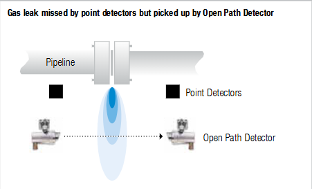
By using a dual bandpass filter, it can fully compensate for various fog, rain, and/or mist interferences.
100% unaffected by the sun, can work normally under partial shading conditions, and has strong anti vibration ability.
Radial symmetrical and bonded window heating, with good low-temperature performance; Coaxial optical systems provide the best performance and resistance to partial occlusion in their class.
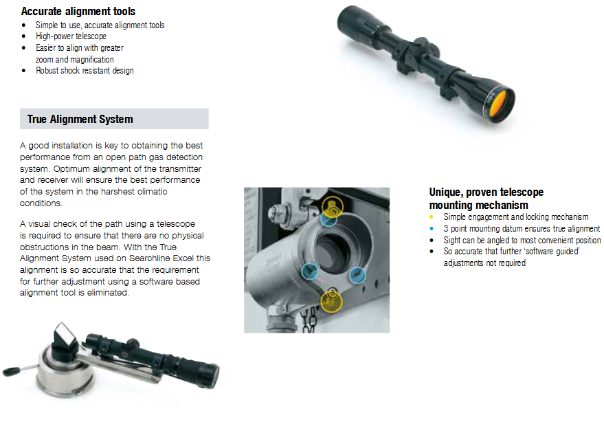
Full temperature compensated solid-state detector with low power consumption under all conditions, equipped with a simple “locking” alignment tool, without the need for additional “software alignment”.
The telescope is designed with higher power and sturdiness, and can be equipped with Modbus RS485 multi-point output. It has obtained FM hazardous area and performance certification.
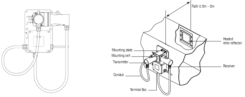
Advantages of open circuit gas detection: As a supplement to point detectors, it has reliable combustible gas detection (verified through use), wider coverage (most likely to detect any leaks), extremely fast response speed, fail safe (no unexposed fault modes, no possibility of gas path blockage), less critical detector position, can indicate the magnitude of danger, simple setup and debugging, and can replace multiple point devices.
Unique technological design
Patent optical design: It is the only solution that can fully address all challenges of open circuit combustible gas detection, using patented dual bandpass filters that can operate accurately and reliably in all weather conditions without relying on software masks that may affect gas detection capabilities.
Coaxial optical design: The unique coaxial optical design makes it the only open circuit gas detector that can operate normally under partial shielding conditions without generating false alarms, while non coaxial instruments may experience false alarms due to differential attenuation.
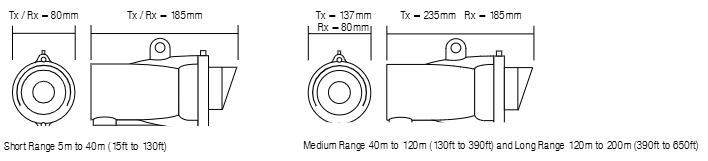
True Alignment System: Good installation is the key to achieving optimal performance for open circuit gas detection systems. This system can achieve precise alignment without the need for software based alignment tools for further adjustments. During installation, a telescope is used to visually inspect the path to ensure there are no physical obstacles.
Accessories and Communication
Main accessories: including XNX universal transmitter (providing local display and enhanced interface options such as relays and modern digital communication, including HART) ®、 Modbus and Foundation Fieldbus ™)、 Unique and validated telescope installation mechanism (with simple engagement and locking mechanism, three-point installation reference to ensure true alignment, and adjustable line of sight to the most convenient position), etc.
Communication function: Can be combined with XNX universal transmitter kit, standard equipped with local HART ® Ports and HART via 4-20mA ®, Can be accessed through the XNX user interface or compatible HART ® Handheld interrogator configuration; In permitted applications, SHC-1 handheld interrogator and SHC-1 protective device module can be used for invasive connection with Searchline Excel. The multi-point Modbus function can significantly save installation and wiring costs, and the bidirectional digital communication protocol allows configuration, warning, and fault diagnosis information to be transmitted back to the control room, reducing maintenance costs.
Recommended alarm setting: (low) 1.0 LEL. m; (Height) 3.0 LEL. m
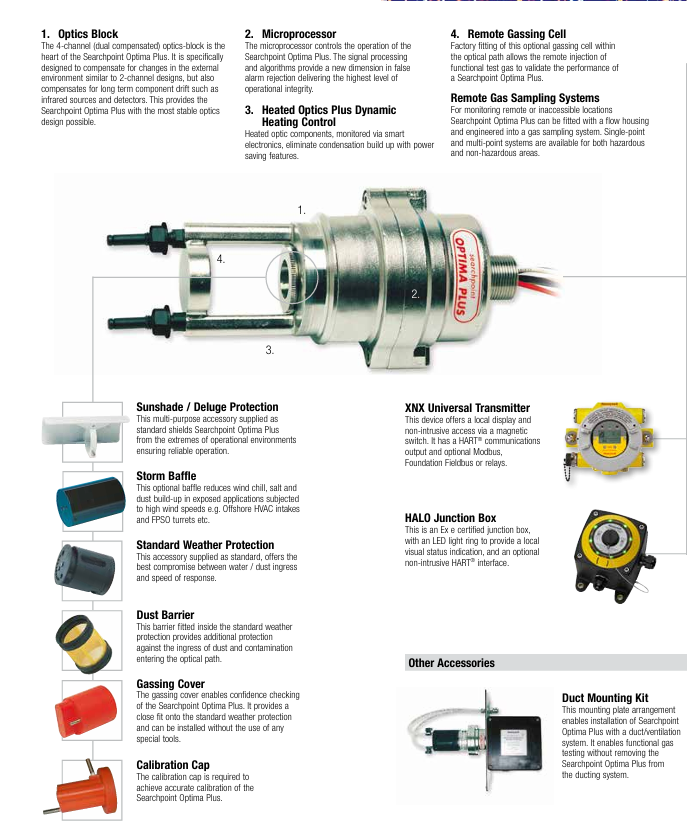
Path length: Short distance 5m to 40m (15ft to 130ft.), medium distance 40m to 120m (130ft to 390ft.), long distance 120m to 200m (390ft to 650ft.)
Response speed: T90 less than 3 seconds (under normal operating conditions)
Output signal: 4-20mA (maximum loop resistance of 600 ohms; Provide source and sink) and RS485, 21mA over range, 4-20mA normal operation (0 to 5 LEL. m), 3mA (1) optical components dirty, 2.5mA (1) beam blocked, 2mA (1), 0mA fault
Digital output: Modbus RS485 multipoint. Use DX100 (M) or XNX universal transmitter with Modbus option
Working humidity: 0 to 99% RH (non condensing)
Work pressure: 91.5 to 105.5 KPa (915 to 1055 mbar) (without compensation)
Preheating time: less than 5 minutes (operable), or less than 1 hour (completely stable)
Power supply: 18V to 32VDC
Power consumption short-range transmitter: 3.5W/5.0W * maximum. Medium to long distance transmitter: 10W/13W * maximum. Receiver: 8W maximum.
Shell material: 316 stainless steel
Weight (including installation bracket): Short distance transmitter: 3.5kg, medium to long distance transmitter: 7kg, receiver: 3.5kg
Vibration 2 to 60Hz, maximum peak to peak amplitude 1mm
Alignment tolerance: short distance ± 0.5 º (at 40m ±~35cm), medium distance ± 0.5 º (at 120m ±~104cm), long distance ± 0.5 º (at 200m ±~170cm)
EMC standard: EN50270
Performance certification: FM performance certification
Safety certification: ATEX, UL, CSA, FM and other certifications
IP rating: IP66 and IP67
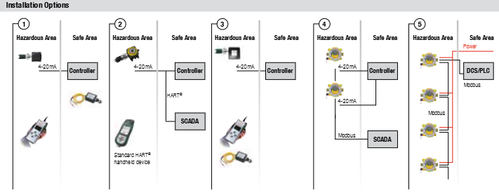
Installation Options
Installation options: Provides multiple installation configurations to meet the different connection requirements of hazardous and safe areas, such as connecting with controllers, DCS/PLC, SCADA systems, etc. It supports communication methods such as 4-20mA and Modbus, and can achieve redundant 4-20mA signal transmission, local invasive/non-invasive inquiry, remote status transmission, and other functions.
Searchpoint Optima Plus is an advanced infrared point type hydrocarbon gas detector suitable for potentially explosive environments. With its infrared detection principle, it has the characteristics of fast response, fault safe operation, etc., which can ensure factory compliance, personnel safety, and maximum uptime of the production process. Compared with traditional electrocatalytic gas detectors, it can reduce daily maintenance and overall cost of ownership.
Global application foundation: Based on over 40 years of design, manufacturing, installation, and maintenance experience, more than 100000 infrared point type hydrocarbon gas detectors have been installed worldwide, with a wide range of application scenarios, from light industry to demanding offshore petrochemical environments.
Typical applications: including environments where catalytic bead toxins or inhibitors may exist, as well as harsh environments that require extended daily maintenance intervals, such as offshore oil and gas platforms, floating production storage and offloading (FPSO) vessels, oil tankers, onshore oil and gas terminals, refineries, LNG/LPG bottling plants, etc.
Detectable gases: Over 100 types of gases and vapors can be detected. For specific lists, please consult the customer support team or local distributors.
Core advantages
Advantages of infrared technology: It has the characteristics of fault safe operation, fast response speed, reduced daily maintenance, not affected by catalytic toxins, long service life, and can work in inert environments.
Product Features:
Accumulated experience in installing over 100000 units worldwide, with higher reliability.
Optional HART ® The protocol outputs through 4-20mA.
Can detect various hydrocarbon gases, including solvents.
No moving parts, higher reliability; The self compensating optical system enhances stability and is not affected by long-term component drift.
Capable of remote functional gas testing and certified for hazardous areas in North America and Europe.
Enhance false alarm elimination capability, with pollution optical warning to improve uptime, dynamic heating control to ensure no condensation or undetected faults in the optical system.
Improved diagnostic functions, integrated event logs, reduced power consumption, and certified through various hazardous area classification schemes such as ATEX, UL, CSA, IECEx, etc.
Core Technologies and Components
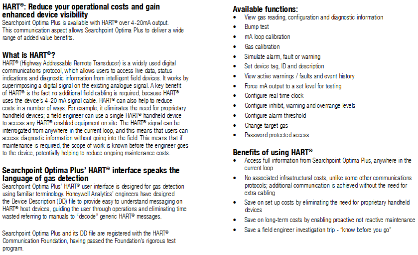
Optical module: The 4-channel (dual compensation) optical module is the core, which not only compensates for external environmental changes like the 2-channel design, but also compensates for long-term component drift such as infrared light sources and detectors, providing the most stable optical design.
Microprocessor: controls the operation of the detector, and its signal processing and algorithms reach new heights in false alarm elimination, providing the highest level of operational integrity.
Heating optical system and dynamic heating control: The heated optical components are monitored by intelligent electronic devices, which have energy-saving functions and can eliminate condensation accumulation.
Remote gas injection unit: The optional remote gas injection unit is installed in the optical path at the factory and can remotely inject functional test gases to verify detector performance.
Sampling system and accessories
Remote gas sampling system: For remote or difficult to access locations, flow enclosures can be equipped and integrated into the gas sampling system, providing single point and multi-point systems suitable for hazardous and non hazardous areas.
Main accessories:
Sunshade/Rain Protection: Standard multifunctional accessories to protect the detector from extreme environmental impacts and ensure reliable operation.
Storm Barrier: Optional barrier to reduce wind chill, salt, and dust accumulation in high wind exposure applications.
Standard weather protection: Standard equipment, achieving the best balance between waterproof/dustproof and response speed.
Dust barrier: Installed inside the standard weather protection, it additionally prevents dust and pollutants from entering the light path.
Gas injection cover: can confirm the performance of the detector, closely matched with standard weather protection, and can be installed without special tools.
Calibration cap: used to achieve accurate calibration of detectors.
XNX Universal Transmitter: Provides local display and non-invasive access through magnetic switches, with HART capability ® Communication output and optional Modbus, Foundation fieldbus, or relays.
HALO junction box: Ex e certified junction box with LED halo for local visual status indication, optional non-invasive HART ® Interface.
Pipeline installation kit: Installation plate device, which can install the detector in the pipeline/ventilation system without removing it from the pipeline system for functional gas testing.
On site inquiry tool: The multifunctional handheld interrogator (SHC-1) is a certified debugging/maintenance tool for hazardous areas, which can reconfigure detectors to adapt to different gases and perform fault diagnosis. It can also be used for raw Searchpoint Optima and Searchline Excel (open circuit gas detectors), reducing operator training.
Terminal/Installation Accessories: Provide a full range of hazardous area certified Ex e and Ex d junction boxes, as well as SHC-1 protective devices, to provide electrical protection for SHC-1 when using conventional terminal enclosures.
HART ® communication protocol
Protocol advantage: HART ® Highway Addressable Remote Transformer is a widely used digital communication protocol that allows users to obtain real-time data, status indicators, and diagnostic information from smart field devices by superimposing digital signals on existing analog signals, without the need for additional field wiring, helping to reduce costs. If dedicated handheld devices are not required, engineers can use a single HART ® Handheld devices access all HART devices on site ® Enable the device and query HART at any position in the current loop ® Signal, diagnostic information can be obtained without the need to go to the site, reducing maintenance costs.
The detector supports functions such as viewing gas readings, configuration, and diagnostic information, conducting collision testing, mA loop calibration, gas calibration, simulating alarms, faults, or warnings, setting device tags, IDs, and descriptions, viewing activity warning/fault and event history, forcing mA output to a specific level for testing, configuring real-time clock, configuring suppression, warning, and over range levels, configuring alarm thresholds, changing target gases, and password protected access.
Technical specifications
Project/Details
Measurement range: 0-100% LEL, calibrated for various hydrocarbon gases and vapors, providing different measurement ranges and solvent calibrations for special applications
Signal output: 4-20mA automatic sensing sink or source, suppression: 1-3mA (default 2mA), warning: 0-6mA (default 3mA *), fault: 0mA (HART) ® Unit adjustable to 1mA, over range: 20-21.5mA (default 21mA)
Digital output: optional multi-point Modbus RS485 via XNX, optional HART ® Through 4-20mA output (HART) ® Version 7)
Operating and certification temperature range: -40 ° C to+65 ° C * *; CU-TR-EX (Russia) certification – XTC version, certified temperature range -60 ° C to+65 ° C
Long term stability (as defined in EN 60079-29-1): baseline methane 100% LEL range: ≤± 2% FSD; Ethylene 100% LEL range: ≤± 4% FSD; 50% FSD methane 100% LEL range: ≤± 4% FSD; Ethylene 100% LEL range: ≤± 5% FSD
Drift within temperature range (-40 ° C to 65 ° C): baseline ≤ ± 2% FSD; 50% FSD methane 100% LEL range: ≤± 0.131% FSD/° C; ethylene 100% LEL range: ≤± 0.078% FSD/° C
Pressure change impact: 0.1% (reading)/mbar
Power supply 18-32Vdc: (nominal 24Vdc), maximum<4.5W
Environmental Protection: IP 66/67
Diagnosis (and recalibration): Certified handheld interrogator, XNX, or optional HART ® communication
Safety certification: ATEX, UL/CSA, IECEx, CU-TR-EX (Russian Customs Union) and other certifications
Performance certification: EN 60079-29-1, CSA C22.2 152., FM ANSI/ISA-12.13.01., Russian mode approval (metrology) – XTC version, etc***
Ship certification: Marine Equipment Directive (MED), DNV, BV, ABS, Lloyd’s Register and other type approvals
Installation Options
Installation options: Provides multiple installation configurations to adapt to different connection requirements in hazardous and safe areas, such as connecting to controllers, DCS/PLC, SCADA systems, etc., supporting HART ®、 Modbus and other communication methods.
The installation must comply with the standards recognized by relevant national authoritative institutions, and reference should be made to EN 60079-14 and EN 60079-29-2 in the European region.
It is strictly prohibited to open the casing when powered on or when there may be explosive atmospheres present.
Operators need to be aware of the measures to be taken when the gas concentration exceeds the alarm level, and must not modify the product structure, otherwise it may render critical safety and certification requirements ineffective.
Only trained personnel are allowed to carry out internal operations of the product. Its measurement function has not obtained ATEX certification, and it is not allowed to rely on the backlight status indication of the OELD display screen for safety related operations. The equipment must not operate in an environment with an oxygen content exceeding 21%.
Special safety conditions for use (increased safety Ex e version)
Each terminal can be connected to a maximum of one single or multiple wires on either side, unless multiple wires are connected in an appropriate manner.
The insulation layer of the wire connected to the terminal should be suitable for the corresponding voltage and extend within 1mm of the terminal throat.
All used and unused terminal screws should be tightened to between 0.5Nm and 0.6Nm, and terminals can only be installed and wired using cables recommended by IECEx KEM 10.0093U.
Disposal and Environmental Protection
The product should be disposed of in accordance with local regulations, including materials such as the shell (aluminum alloy or 316 stainless steel), lid (aluminum alloy or 316 stainless steel, glass).
The product must be disposed of through appropriate WEEE disposal facilities and cannot be treated as general industrial or household waste.
Product Overview
Basic Introduction
OELD is a certified junction box for hazardous locations, suitable for detectors with 4-20mA output, and can be used in conjunction with Searchpoint Optima Plus or Searchline Excel series gas detectors.
Provide local visual status indication and Bluetooth low-energy interface, which can be configured and maintained through Bluetooth enabled mobile devices, certified by ATEX and IECEx, suitable for Zone 1 (gas) or Zone 21 (dust) hazardous areas, and the explosion-proof version also has cULus certification, suitable for Class I Zone 1 or Class II Zone 1.
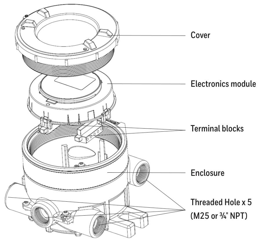
There are 5 entrances (M25 or 3/4 “NPT depending on the version) and 3 certified plugs, while the Ex e version of the OELD only has 5 M25x1.5 entrances.
Structure and function
There are two grounding connection points and an electronic module with two pluggable terminal blocks inside the shell, used to connect the field and detector wiring.
Featuring four-color backlighting (green, yellow, red, blue) and a customized 7-segment liquid crystal display (LCD), different backlight colors represent different states, such as green for normal operation or warning, red for alarm, etc.
Options
Including pipeline installation kit (1226A0358), which can install OELD on pipelines with diameters ranging from 2 “to 6” (50 to 150mm); Ceiling installation bracket kit (1226A0355), used for ceiling installation; Sun visor (94000-A-1006), made of 316 stainless steel, can protect OELD and related detectors from direct sunlight.
Installation related
Site selection and positioning
The placement of gas detectors should follow the recommendations of gas diffusion experts, process equipment experts, safety personnel, and engineering personnel, and record the protocol for determining the detector location.
Installation designers should refer to IEC/EN 60079-29-2 and other national practice standards, as well as the site selection recommendations for specific locations in the gas detector technical manual.
Mechanical Installation
OELD can be installed in various ways through integrated mounting pads, such as on flat walls Unistrut ® On the bracket, use the optional pipe installation kit to install on the pipeline or utility pole, or use the ceiling installation bracket kit to install on the ceiling.
When installing, it is necessary to consider the correct direction of the detector, ensure that the installation bolts are fully tightened, and use appropriate locking washers.
electrical installation
The detector can be installed directly or remotely to the OELD, and some detectors have corresponding junction boxes for remote installation.
The installation steps include removing the cover, taking out the electronic module, installing cable glands or conduit fittings, installing detectors (with different installation methods for different entrance versions), sealing unused cable entrances, making electrical connections, reinstalling the display module and cover, etc.
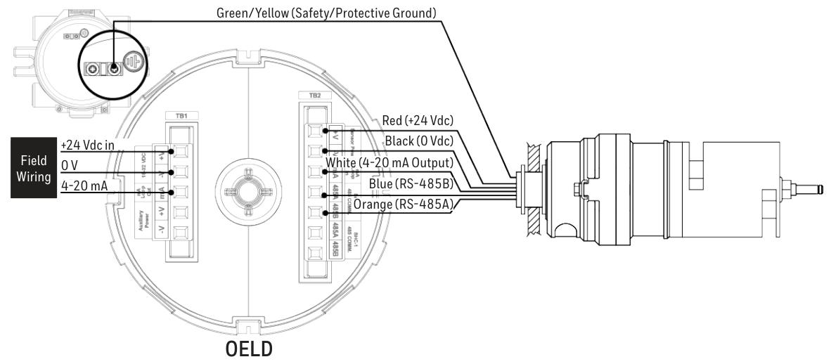
Electrical connection
Terminal block definition
Terminal block 1 (TB1) and terminal block 2 (TB2) have different markings, colors, and functions for each terminal. For example, terminal 1 of TB1 is – V (black) and is used for auxiliary power supply.
The increased safety (Ex e) version uses terminal blocks of specific manufacturers and types, while the explosion-proof (Ex d) version is black and the increased safety version is green. They must not be mixed, otherwise the product certification will be invalidated.
Wiring diagram
Provided OELD and Searchpoint Optima Plus、Searchline Excel、Searchline Excel Cross-Duct(XD) Wait for the wiring diagram of the detector, as well as the connection method of the detector with the current sink and current source configuration.
Grounding connections should avoid grounding loops. The OELD has two internal grounding points, and the on-site cable shielding layer should be connected to the instrument grounding in the control room. The internal and external grounding points of the OELD have corresponding specifications and connection requirements.
Power supply and cables
The OELD requires a voltage supply of 18-32Vdc (nominal 24Vdc) with a maximum power consumption of 2W, taking into account the voltage drop caused by cable resistance to ensure the minimum required supply voltage at the detector.
The cable should be suitable for hazardous area classification and comply with relevant regulations. It is recommended to use industrial grade shielded field cables. The allowable wire size for terminals is 0.2-2.5mm ² (24-12AWG), and the rated wire temperature should be greater than 80 ° C. The terminal tightening torque should be 0.5Nm to 0.6Nm.
Configuration
Configurable parameters
Including local alarm indication threshold (can be set between 5 and 65% FSD, default 20% FSD), mA input level setting (to match the detector’s mA output curve), and OELD universal display settings (such as full-scale range, measurement unit, gas name, etc.).
configuration process
Configure by running the OELD App on a mobile device, including steps such as launching the application, logging in, searching for nearby OELD units, selecting and confirming connections, etc.
After completing the configuration or changing the settings, the configuration should be read back and verified to ensure that the changes are correct.
Operation
Startup and self-test
The startup and self-test sequence takes about 60 seconds, during which display testing, backlight testing, internal hardware and memory checks, etc. will be performed. After completion, it will enter normal operating mode.
normal operation
During normal operation, the LCD backlight indicates the detector status based on the 4-20mA output of the detector, and different current ranges correspond to different backlight colors and flashing states.
The display screen displays gas concentration information (in graphical and numerical form) and other information during normal operation. At low temperatures, the refresh rate of the display screen will automatically decrease. At extremely low temperatures, the screen clarity may decrease, but it can return to normal after the temperature is restored.
communication model
Equipped with Bluetooth Low Energy (BLE) interface, it supports non-invasive connection with mobile devices running the OELD App, and can also communicate with specific detectors through RS-485 interface.
Honeywell Analytics SHC-1 handheld interrogator and SHC protection device can also be used to connect with relevant detectors, but attention should be paid to relevant warnings and precautions.
OELD Mobile Application
Installation and operation
The OELD mobile application can run on Android 4.3 (Jelly Bean) or higher operating systems that support Bluetooth Low Energy (BLE) and can be downloaded and installed from the Google Play Store.
The first launch requires reading the End User License Agreement, logging in or registering an account. Registration requires an Internet connection and at least one OELD device’s QR code.
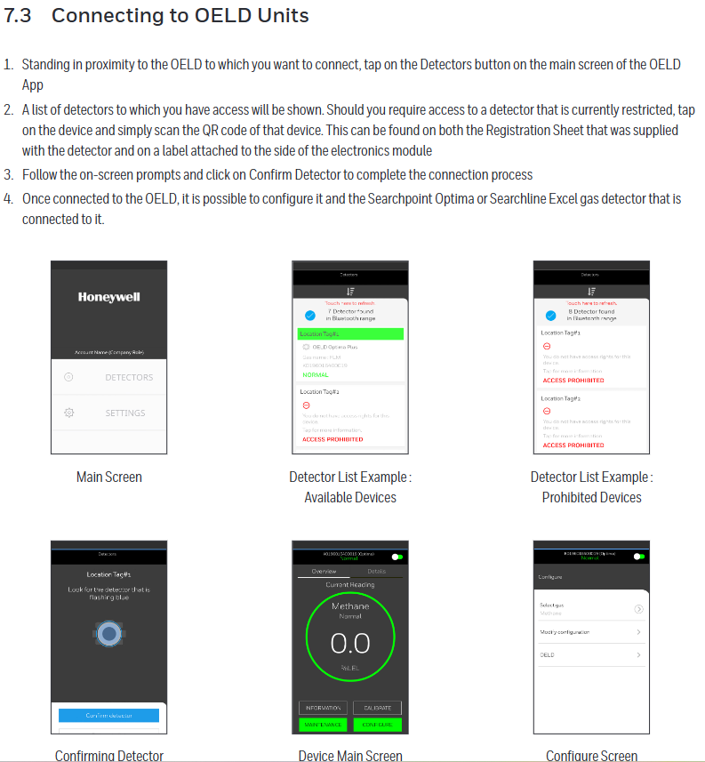
Connection and Configuration
Can connect to OELD devices that have already been registered to the user account. The connection steps include clicking on relevant buttons on the main screen of the application, selecting the device, scanning the QR code (if access to restricted devices is required), confirming the connection, etc.
Multiple parameters of the OELD device can be configured, as well as parameters of detectors such as Searchpoint Optima Plus and Searchline Excel connected to the OELD, and calibration operations can also be performed (specific detectors).
Maintenance and troubleshooting
maintenance
Regularly inspect the OELD and cables for physical damage, clean the glass windows with a damp cloth, and do not use solvents or abrasive cleaners. The OELD has no user repairable parts.
It is recommended to check the configuration and operation of the equipment at least once a year, and the gas detector connected to the OELD should be checked and calibrated according to its operating instructions.
The replacement of the display module requires following specific steps, including power-off, removing the cover and electronic module, replacing the module, etc. After replacement, it needs to be reconfigured.
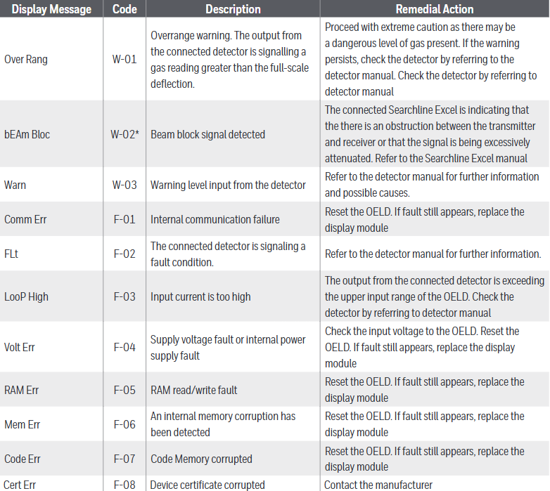
Malfunctions and warnings
Different display messages and codes correspond to different types of faults or warnings, such as “Over Rang” (W-01) indicating an over range warning, “Comm Err” (F-01) indicating an internal communication fault, etc., with corresponding remedial measures.
Specifications and ordering information
specifications
The material is marine grade aluminum alloy or 316 stainless steel (with 5-coated painted surface treatment), and the weight varies depending on the material. The size is 159x197x114mm, and the number and type of cable entrances vary depending on the version. There are corresponding terminals, storage and working temperatures, humidity, display information, visual indicators, power supply, interfaces, protection levels, and certifications.
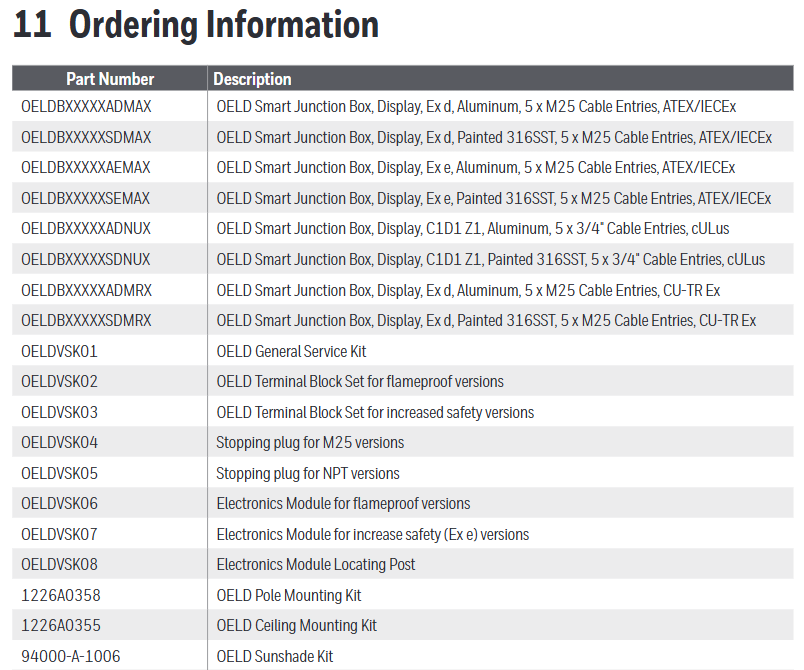
ordering information
We provide models and descriptions of different versions of OELD smart junction boxes and related accessories (such as universal service kits, terminal block groups, plugs, installation kits, sunshades, etc.). We warn that it is necessary to obtain service kits that match the OELD version, otherwise the product certification will be invalidated.
Certification and Warranty
Certification and Approval
Including EU conformity declaration, hazardous area certification (such as ATEX, IECEx, cULus, Inmetro, etc.), performance certification, wireless certification, etc. Different certifications have corresponding certificate numbers and scope of application.
Warranty Summary
Honeywell Analytics guarantees that the OELD will be free of component and process defects, repairable or replaceable under correct use for a period of 24 months from the date of shipment, excluding consumables, normal wear and tear, accidental damage, etc. Claims must be made within the warranty period.
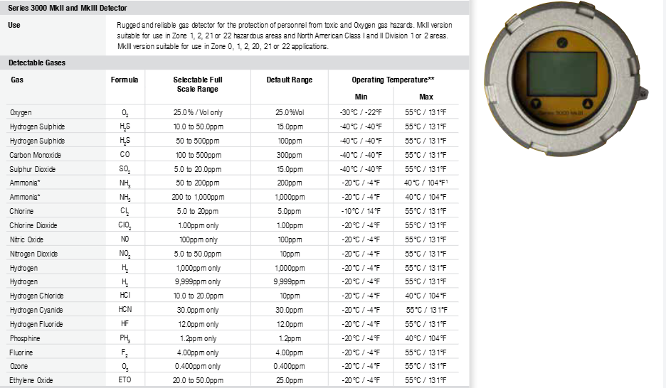
The Honeywell Series 3000 MkII and MkIII are 2-wire loop powered toxic gas and oxygen detectors suitable for potentially explosive environments. They come in explosion-proof and intrinsic safety versions, capable of comprehensively monitoring toxic gas and oxygen hazards. They are suitable for indoor and outdoor installation and have excellent versatility.
MkII: Equipped with a flameproof casing and sensor connections that are inherently safe, it is mainly suitable for Zone 1 locations. When paired with an optional remote installation kit, the sensor can be installed in Zone 0 environments.
MkIII: It needs to be used in conjunction with a separate suitable intrinsic safety barrier and can be used in Zone 0, Zone 1, Zone 2, Zone 20, Zone 21, or Zone 22 locations.
Core advantages
Reliable detection: using mature electrochemical sensing technology and Surecell ™ Electrochemical batteries are suitable for high temperature and high humidity environments, with long sensor life and patented “Reflex” sensor verification and diagnostic functions.
Reduce installation costs: Equipped with integrated surface mount lugs, providing optional horizontal or vertical pipe mounting brackets, explosion-proof transmitters allow for on-site wiring to be laid together with other non intrinsic safety instruments, plug-in sensors do not require wiring and can replace Series 2000 series for refurbished installation.
Reduce debugging costs: The sensor recognition function can automatically configure the transmitter, support non-invasive configuration, and be equipped with plug and play factory configured sensors.
Reduce maintenance costs: Intrinsically safe sensor connections allow for hot swapping, reducing downtime. Users can set calibration frequencies and have integrated fault diagnosis software and menu/icon driven calibration programs.
Regulatory compliance: Complies with regulatory requirements in Europe (ATEX), the United States (UL), Canada (c-UL), South America (Inmetro), International (IECEx), and other regions.
Installation related
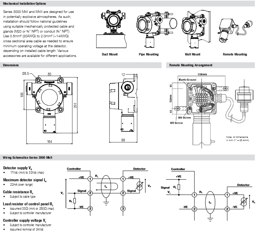
Installation method: Integrated installation ears can be used for wall mounting, or optional pipeline installation kits can be used for pipeline installation (horizontal or vertical). It also supports pipeline installation, remote installation, etc.
Electrical installation: ATEX/IECEx version uses 2 M20 cable entries, UL/c-UL version uses 2 three-quarters “NPT conduit entries, equipped with suitable plugs to seal unused entries, including weatherproof caps to withstand the harshest outdoor conditions.
Cable requirements: Depending on the length of the installed cable, cables with a cross-sectional area of 0.5mm ² (20AWG) to 2.0mm ² (approximately 14AWG) should be used to ensure the minimum operating voltage of the detector.
Size: The transmitter size is 164mm x 201mm x 99mm (6.4 “x 7.9” x 3.9 “), and other related components have their own specific sizes.
Weight: LM25 aluminum alloy material weighs approximately 1.7kg (3.75lbs), 316 stainless steel material weighs approximately 3.7kg (8.16lbs).
Electrical specifications
Power supply: The MkII is powered from 17Vdc (± 10%) to 32Vdc (maximum), with a maximum current of 22mA (over range); The MkIII is powered from 10Vdc (± 10%) to 30Vdc (maximum), with a maximum current of 22mA (out of range).
Signal output: 0-100% full range 4-20mA, fault status 3mA, calibration expiration can choose to turn off or output 3mA, maximum over range 22mA, toxic sensor suppression can choose 3mA or 4mA, oxygen sensor suppression can choose 3mA or 17.4mA.
Cable length: The maximum cable length of MkII depends on the minimum guaranteed power supply voltage of the controller, the minimum operating voltage of the detector, the maximum current consumption of the detector, the input impedance of the controller, and cable resistance, etc; When calculating the maximum cable length for MkIII, the limiting factors are total capacitance and inductance, which need to consider the fixed capacitance and inductance of barriers and isolators, as well as the capacitance and inductance per meter or kilometer of the cable.
Wiring schematic: MkII and MkIII have their own different wiring schematic, and MkIII also provides some recommended barriers and isolators for use.
Technical parameters
Detectable gases: including oxygen (O ₂), hydrogen sulfide (H ₂ S), carbon monoxide (CO), sulfur dioxide (SO ₂), ammonia (NH ∝), and other gases, each with a corresponding optional full-scale range and default range.
Working temperature: Different certification versions and models vary. The ATEX/IECEX version MkII ranges from -20 ° C to+55 ° C (-4 ° F to+131 ° F), while the MkIII ranges from -40 ° C to+55 ° C (-40 ° F to+131 ° F); The UL/c-UL version is from -40 ° C to+55 ° C (-40 ° F to+131 ° F).
Working humidity: Continuous 20-90% RH (no condensation), intermittent 0-99% RH (no condensation).
Work pressure: 90-110kPa.
Storage conditions: 15 ° C to 30 ° C (59 ° F to 86 ° F), 30-70% RH (non condensing).
Protection level: IP66 (EN 60529), NEMA 4X.
Construction materials: The transmitter is made of epoxy coated aluminum alloy LM25 or 316 stainless steel, and the sensor is made of 316 stainless steel with PTFE filter.
Authentication information
MkII: UL/c-UL certification is applicable to Class I Zone 1 and Zone 2, Groups B, C, D, etc; ATEX and IECEx also have corresponding certifications.
MkIII: UL/cUL certification is applicable to Class I, Zone 1 and Zone 2, Groups A, B, C, D, etc; ATEX and IECEx also have corresponding certifications.
Remote sensor accessories: have also obtained relevant certifications such as UL/c-UL, ATEX, IECEx, etc.
The product complies with CE standards and follows ATEX Directive 94/9/EC, EMC Directive 2004/108/EC, EN 50270, etc.
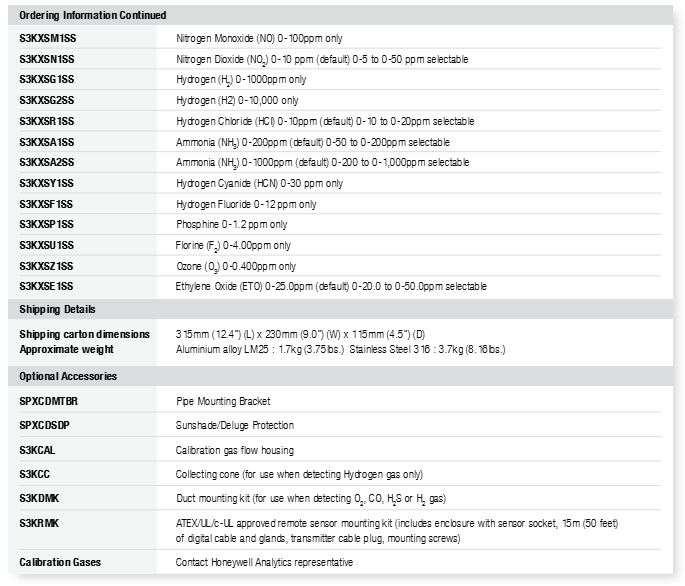
Order Information
Complete components: consisting of transmitter and sensor, which need to be ordered separately.
Transmitter models: There are ATEX/IECEx certified versions, UL/CSA certified versions, Inmetro certified versions, each with aluminum alloy and stainless steel materials, as well as MkII and MkIII models.
Sensor model: All sensors are certified by ATEX, IECEx, UL, CSA (c-UL), and the gas type and range are specified by two digits. Different gases correspond to different models.
Optional accessories: including pipeline installation brackets, sun/rain protection devices, calibrated gas flow enclosures, collection cones, pipeline installation kits, remote sensor installation kits, etc.
Calibration gas: You can contact a Honeywell Analytics representative to obtain it.
Honeywell’s Sensepoint series of gas detectors covers combustible gas, toxic gas, and oxygen detectors, providing high-quality, low-cost solutions for industrial gas monitoring needs. They are suitable for new construction and renovation projects and demonstrate high performance and reliability in a variety of demanding applications.
Core advantage: Adopting mature sensor technology such as Surecell ™ Electrochemical sensors, anti poisoning catalytic beads, fast and reliable response, with a typical service life of 2-5 years for sensors; Certified by ATEX/IECEx, in compliance with the latest standards, with hazardous area use permit and corresponding performance; The protection level reaches IP65/67, which can be used in harsh environments; The factory preset operation is easy to replace, requires less training, and also provides various accessories such as weather caps, flow adapters, etc.
Adaptability: Suitable Ex d or Ex e certified junction boxes should be used to install in potentially explosive environments, with output that meets industry standards and can be connected to Honeywell Analytics controllers or third-party DCS/PLC systems.
Characteristics of different types of detectors
Combustible gas detector: available in% LEL or PPM detection range versions, providing industry standard mV bridge output, with a typical lifespan of over 5 years, and can be replaced directly upon expiration.
Toxic gas detector: pre calibrated, easy to install, providing industry standard 2-wire 4-20mA loop output; The user connection is Ex d type, and the front-end intrinsic safety (IS) design allows for live replacement of replaceable sensors without sintering, with a fast response speed to “viscous” gases such as chlorine and ammonia.
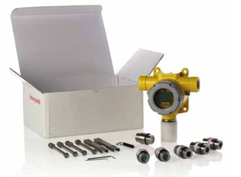
Installation details
Dimensions: There are differences in some dimensions between combustible gas (% LEL or PPM version) and toxic or oxygen versions, such as 90mm and 74mm for combustible gas detectors, and 56mm for toxic gas detectors.
Junction box and installation: Use appropriate Ex d or Ex e junction boxes for installation. The standard junction box provided by Honeywell Analytics includes a grounding continuity board to enhance RFI protection; The detector has multiple installation thread sizes to choose from to match local preferences, and can be used in conjunction with Honeywell Analytics’ various controllers or third-party control devices that accept its industry standard output signals.
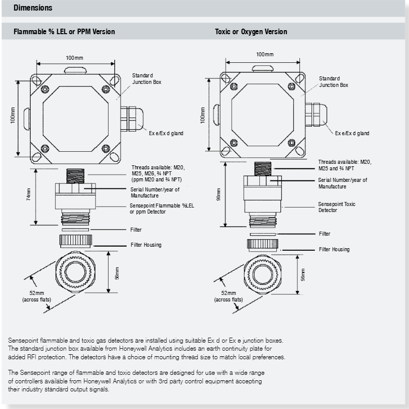
Electrical connection: Different types of detectors have different wiring methods. The combustible gas% LEL version uses a 3-wire mV bridge circuit, the toxic or oxygen version uses a 2-wire 4-20mA (Sink) system, and the combustible gas PPM version uses a 3-wire mV bridge circuit.
Technical specifications
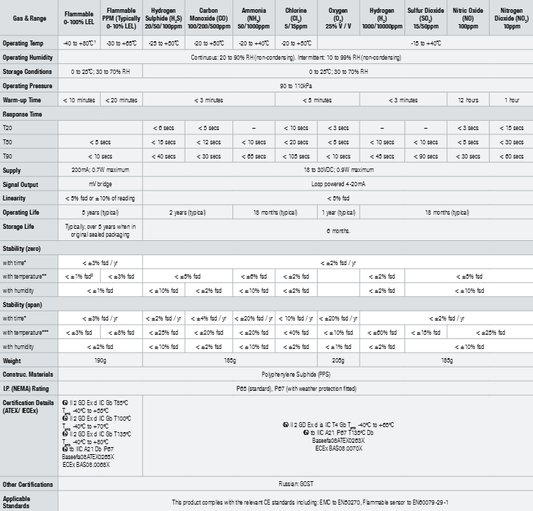
Covering multiple gases and detection ranges, detectors corresponding to different gases have differences in working temperature, working humidity, storage conditions, working pressure, preheating time, response time, power supply, signal output, linearity, working life, storage life, stability, weight, construction materials, protection level, certification details, etc.
For example, the working temperature of combustible gas 0-100% LEL version is -40 to+80 ° C (high temperature version -55 to+150 ° C), and the signal output is mV bridge; Hydrogen sulfide (H ₂ S) 20/50/100ppm version operates at temperatures ranging from -25 to+50 ° C, with a typical lifespan of 18 months.
In terms of certification, combustible gas detectors and toxic gas detectors comply with different ATEX/IECEx standards, and some also have Russian GOST certification and comply with relevant CE standards.
Order Information
Accessories: including terminal housing, right angle mounting bracket, Series 2000 weatherproof housing, collection cone, calibration flow housing component, catalytic bridge to 4-20mA converter, toxic gas calibration kit, threaded adapter, cable sealing sleeve and cap, etc. Each accessory has corresponding models.
Spare parts: mainly various electrochemical battery replacement kits, corresponding to different gases such as oxygen, sulfur dioxide, chlorine gas, carbon monoxide, etc., each kit has a specific model.
Sensors: Combustible gas sensors and various toxic gas and oxygen sensors, with multiple models available for selection based on gas type, detection range, and thread type.