Bently 330500 Velomitor piezoelectric velocity sensor
Product Overview
Core functions
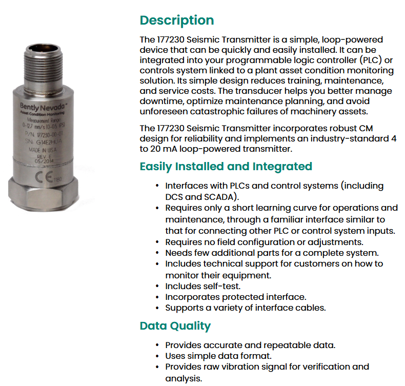
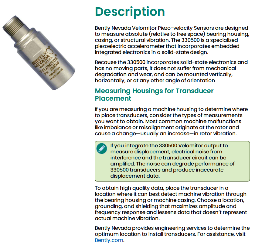
The 330500 Velomitor piezoelectric velocity sensor is a special type of piezoelectric accelerometer that uses solid-state design and integrates embedded electronic components for measuring absolute vibration (relative to free space) of bearing seats, housings, or structures. It has no moving parts, avoiding mechanical degradation and wear, and can be installed vertically, horizontally, or at any angle.
Application points
Suitable for detecting vibration changes caused by common faults such as rotor imbalance and misalignment.
If the integral output is used to measure displacement, it should be noted that electrical noise may amplify and affect data accuracy. Therefore, it is necessary to choose the installation position, grounding, and shielding method reasonably to maximize amplitude and frequency response and reduce non actual vibration data interference.
We can provide engineering services to determine the optimal installation location. For more information, please visit Bently.com.
Technical specifications
1. Electrical parameters
Sensitivity: 3.94mV/mm/s (100 mV/in/s) ± 5%.
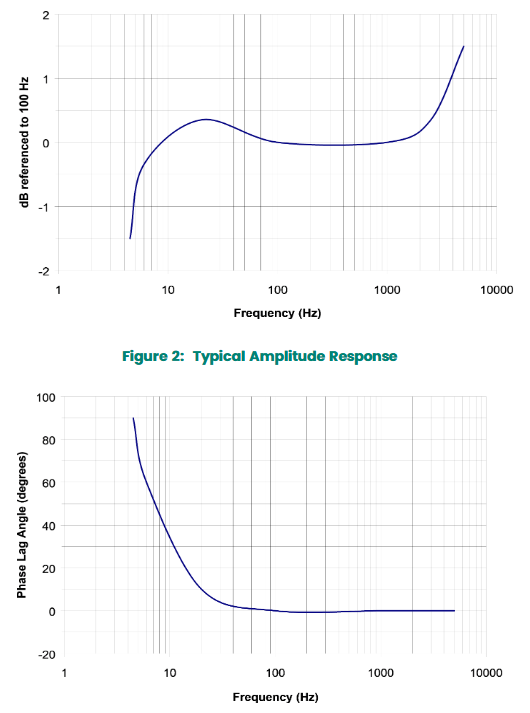
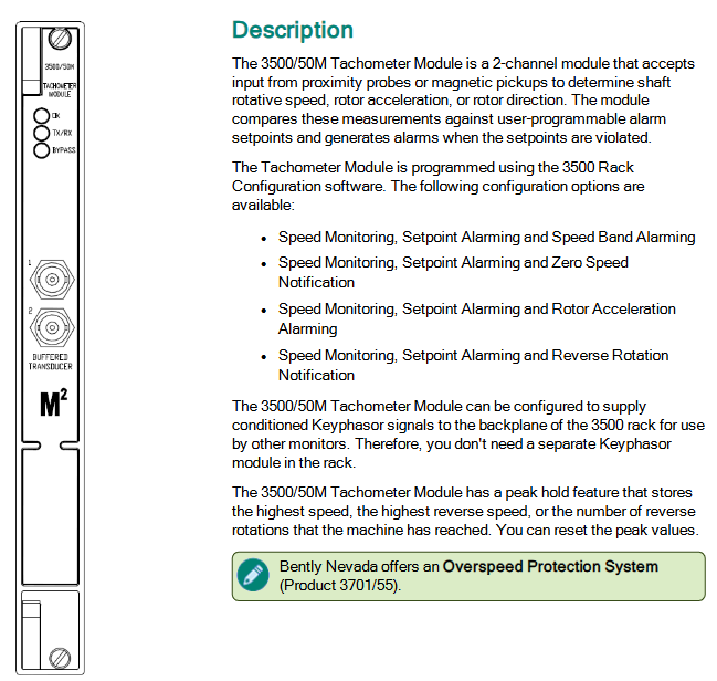
Frequency response: 4.5 Hz to 5 kHz (270 cpm to 300 kcpm) ± 3.0 dB; 6.0 Hz to 2.5 kHz (360 cpm to 150 kcpm) ± 0.9 dB.
Temperature sensitivity: The typical value within the working temperature range is -14% to+7.5%.
Speed range: 1270 mm/s (50 in/s) peak.
Lateral sensitivity: less than 5% of sensitivity.
Amplitude linearity: ± 2% (up to a peak of 152 mm/s (6 in/s)).
Installation resonance frequency: greater than 12 kHz.
Output bias voltage: -12 ± 3.0 V DC (relative to pin A, full temperature range).
Dynamic output impedance: less than 2400 Ω.
Broadband noise floor (4.5 Hz to 5 kHz): 0.004 mm/s (160 μ in/s) rms (nominal value).
Grounding: Shell isolation.
Maximum cable length: With the 02173006 cable model, it can reach 305 meters (1000 feet) without signal attenuation.
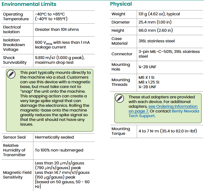
2. Environmental restrictions
Working temperature range: -55 ° C to 121 ° C (-67 ° F to 250 ° F).
Impact bearing capacity: 5000 g peak (maximum).
Relative humidity: 100% non submerged state; The shell is sealed in an airtight manner.
Base strain sensitivity: 0.005 in/s/µ strain.
Magnetic field sensitivity:<51 µ in/s/Gauss (50 Gauss, 50-60Hz).
3. Physical parameters
Weight: Typical value of 142 grams (5.0 oz).
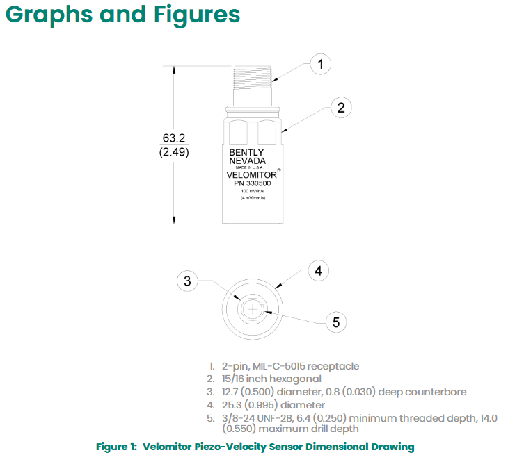
Diameter: 25.3 mm (0.995 in).
Height: 63.2 mm (2.49 in).
Shell material: 316L stainless steel.
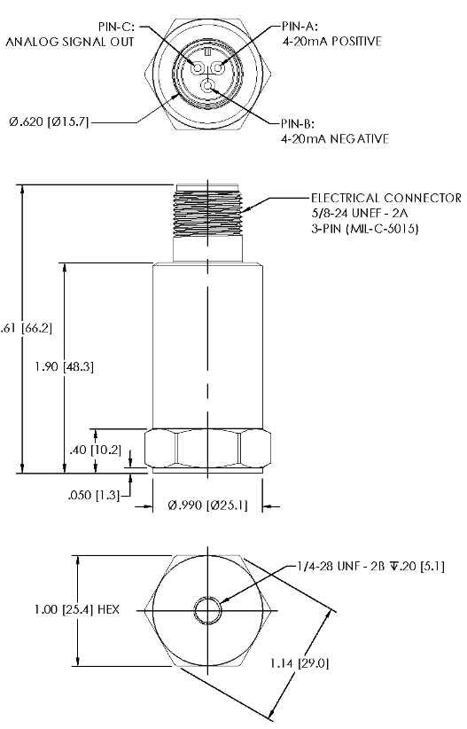
Connector: 2-pin Mil-C-5015 airtight package, 316L stainless steel shell.
Installation torque: Maximum 32-46 kg · cm (24-40 in lb).
Polarity: When the sensor housing moves towards the connector, pin A is positive relative to pin B.
Compliance and Certification
1、 Basic compliance certification
FCC certification
This device complies with Part 15 of FCC regulations and requires two conditions for operation:
Shall not cause harmful interference;
We must accept any interference received, including interference that may cause unexpected operations.
EMC Directive
Compliant with the European Community EMC Directive 2014/30/EU, meeting electromagnetic compatibility requirements in industrial environments, including immunity and emission limits.
RoHS Directive
Compliant with RoHS Directive 2011/65/EU, restricting the use of specific hazardous substances in electronic and electrical equipment, environmentally compliant.
Maritime certification
Only models 330400 and 330425 comply with:
The ABS 2009 Steel Ship Rules (1-1-4/7.7, 4-8-3/1.11.1, 4-9-7/13) are applicable to ship and offshore platform scenarios.
2、 Hazardous Area Certification
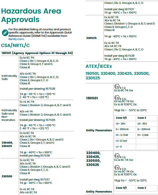
1. CSA/NRTL/C certification
Intrinsic safety type (Ex ia IIC T4):
Applicable to Class I, Div 1, Groups A, B, C, D; Class II,Groups E、F、G; Class III。
Installation must follow drawings 167536/167537/167538, with an ambient temperature range of -40 ° C ≤ Ta ≤+100 ° C (-40 ° F ≤ Ta ≤+212 ° F).
Intrinsically safe and non flammable (Ex nL IIC T4/AEx nA T4):
Suitable for Class I, Div 2, Groups A, B, C, D, installation requirements are the same as above.
2. ATEX/IECEx certification
Covering models such as 190501, 330400, 330425, 330500, 330525, etc., the specific details are as follows:
Zone 0/1(II 1 G Ex ia IIC T4 Ga):
Entity parameters: Ui=28V-30V, Ii=150mA-200mA, Pi=0.75W-1.26W, Ci=10.8NF (some models), Li=0。
Devices that meet the above parameters need to be connected, and cables must comply with EN 60079-25 standard type A or B.
Zone 2(II 3 G Ex nA IIC T4 Gc / Ex tc III T130°C Dc):
The power supply parameters shall not exceed the limits of Ui, Ii, and Pi mentioned above, and the ambient temperature shall be -55 ° C ≤ Ta ≤ 121 ° C.
3、 Certification conditions and precautions
INSTALLATION REQUIREMENTS
When used in hazardous areas, installation must be carried out according to specified drawings (such as 167536, 167537, 167538, etc.) to ensure that cable types and connection methods comply with certification specifications.
Temperature limit
The environmental temperature range under different certifications must be strictly followed (such as the highest environmental temperature corresponding to T4 level), and exceeding the range may result in certification failure.