Positioning and attribution: The core component of the HIMA intelligent safety platform on the field side, used for distributed safety signal acquisition and transmission, directly connecting field devices with HIMax/HIMatrix safety controllers (SIS), replacing the traditional architecture of “field devices → marshalling cabinets → SIS”.
Core application scenario: Industrial site safety signal integration, especially suitable for Zone 2 explosion-proof environments and harsh working conditions (such as high dust and humid environments).
Hardware and Physical Specifications
Category key parameter details
Shell and protective shell material 316L stainless steel, 2mm wall thickness
Protection level IP66/NEMA 4X (compliant with IEC 60529)
Explosion proof rating suitable for Zone 2 environment
Physical dimensions (h/w/d) 1200x800x400mm
Weight 120-150kg (depending on equipment configuration, excluding packaging)
Installation and locking installation method Wall mounted
Lock design with key lock to ensure safety protection
Interface configuration: 2 power supply interfaces, supporting 100-240VAC or 110-250VDC
2 communication interfaces, supporting fiber optic (single-mode) or CAT 6 copper cable (1000 BaseT Ethernet)
Up to 96 I/O interfaces, connected through a multi cable transmission system
Module Series Module Model Function Description Key Parameters
HIMax X-CPU 31 processor module (with system bus connection) SIL 3/Category 4/PL e/CENELEC SIL 4
X-SB 01 System Bus Module SIL 3/Category 4/PL e/CENELEC SIL 4
X-DI 32 01 digital input module 32 channels, 24VDC
X-AI 32 01 Analog Input Module 32 Channels, 4-20mA, with Line Monitoring
X-AI 16 51 Analog Input and Temperature Module 16 Channels, Galvanically Isolated, Supports Thermocouples/Pt100/4-20mA
X-DO 32 01 digital output module 32 channels, 24VDC, 0.5A, with short circuit monitoring
X-DO 24 01 digital output module 24 channels, 24VDC, 0.5A, with line monitoring (LS/LB)
X-AO 16 01 Analog Output Module 16 Channels, 4-20mA, Galactically Isolated in Pair
X-HART 32 01 HART interface module with 32 modems
X-BLK 01 empty module 1 slot, compatible with X I/O series
HIMatrix F35 034 compact device with 24 digital inputs, 8 analog inputs, 2 counter inputs, and 8 digital outputs
F3 AIO 8/4 014 Remote I/O Devices 8 Analog Input (0-10V)+4 Non Safe Analog Output (0-20mA)
F3 DIO 20/8 024 remote I/O device 20 digital inputs (with cross line monitoring)+8 digital outputs
F1 DI 16 01 Remote I/O Device 16 Digital Input (with Crossline Monitoring)
F2 DO 16 014 Remote I/O Device 16 Digital Output, 24VDC, 1A Output Current
(2) Unified standard for security level
All compatible modules meet the SIL 3 safety level, with some supporting Category 4, PL e, or CENELEC SIL 4 levels, meeting the stringent requirements of industrial safety control.
Communication and integration characteristics
Communication mode: support two mainstream communication media, adapt to different transmission distance requirements:
Fiber optic: Single mode fiber optic, suitable for long-distance signal transmission;
Copper cable: CAT 6 standard, supports 1000 BaseT Ethernet, suitable for short distance high-speed communication.
Integration advantages:
Direct connection to SIS: No need for intermediate marshalling cabinets, simplifying signal transmission links;
Pre configuration testing: Complete configuration and testing before leaving the factory to shorten on-site debugging time;
Flexible adaptation: Supports redundant or single system architecture for HIMax/HIMatrix controllers, and can combine modules as needed.
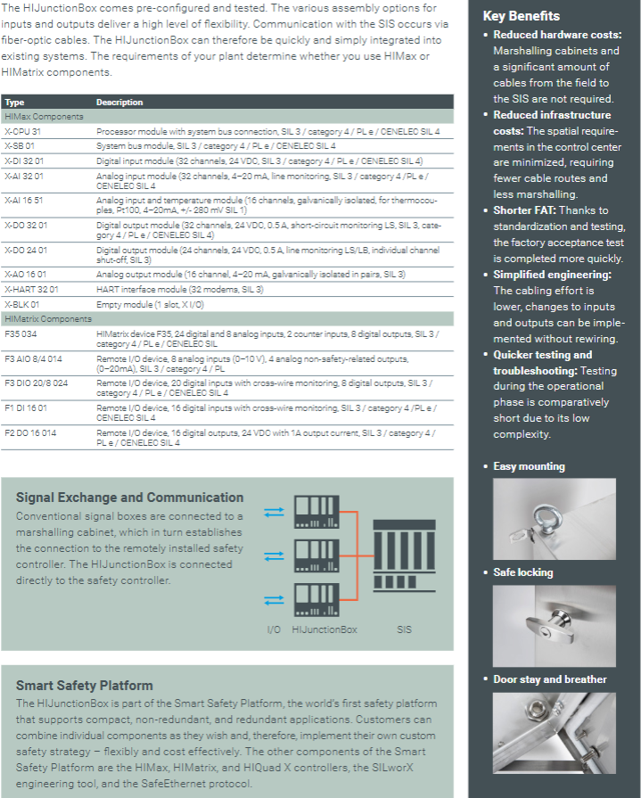
Core advantages
Cost optimization: Reduce the procurement and installation costs of marshalling cabinets, decrease the amount of cables used from the site to SIS, and minimize the space occupation in the control center;
Efficiency improvement: Standardized design shortens FAT (Factory Acceptance Testing) cycle, simplifies wiring engineering, and eliminates the need for rewiring for I/O changes;
Strong reliability: IP66 protection+316L stainless steel shell, suitable for harsh industrial environments, Zone 2 explosion-proof certification expands application scenarios;
High flexibility: compatible with multiple security modules, supports custom security policies, and adapts to the needs of industrial sites of different scales.
HIMatrix F35 is a high safety compact programmable electronic controller launched by HIMA, designed specifically for industrial automation safety control scenarios. It can replace traditional decentralized relay circuits and is suitable for safety related functions such as emergency shutdown, process protection, and equipment interlocking. This controller has been certified by T Ü V and supports up to SIL 3 safety level (compliant with IEC 61508, IEC 61511, IEC 62061 standards). It also meets safety specifications such as EN 954-1 Cat.4 and EN ISO 13849-1 PL e, and is suitable for Zone 2 hazardous environments (compliant with EC Directive 94/9/EG ATEX directive). Some models can be used in underwater scenarios (compliant with ISO 13628-6 standard).
2. Model variants and environmental adaptation
The controller offers 6 variants, each adapted to different programming tools and usage environments, with the following core differences:
Model Programming Tool Operating Temperature Special Design Applicable Scenarios
F35 01 ELOP II Factory 0~60 ℃ Standard Metal Shell Conventional Industrial Environment
F35 011 (-20 ℃) ELOP II Factory -20~60 ℃ Electronic components coated with protective paint Low temperature industrial environment
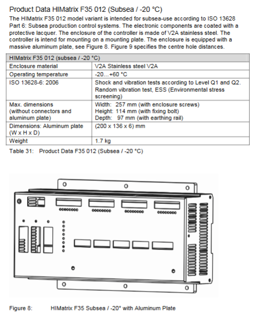
F35 012 (Subsea/-20 ℃) ELOP II Factory -20~60 ℃ V2A stainless steel shell, impact and vibration resistant subsea production control system
F35 01 SILworX SILworX 0~60 ℃ Standard Metal Shell Conventional Industrial Environment (OS ≥ 7 version)
Wiring and power supply: divided into 3 groups (8 channels per group), each group is powered by independent LS+(24V), supporting passive mechanical contacts and active signal source connections, with a maximum wiring distance of 300m;
Safety feature: Following the principle of “power-off tripping”, a low-level safety state is output in case of a fault, and channel faults are fed back through ERROR CODE.
Electrical characteristics: Non isolated, common ground (L -) design, output voltage of L+minus 2V, maximum internal voltage drop of 2W (at 2A), leakage current ≤ 1mA (at low level);
Overload protection: Automatic power-off in case of single channel overload, and automatic restoration after fault relief; When the total current exceeds 7A, all outputs will be powered off and the cycle will retry;
Wiring requirements: The 1-pole switch output should be paired with the corresponding channel group’s L-ground (2-pole connection), and it is recommended to parallel protect diodes for inductive loads;
Safety feature: When a module or channel fails, the output switches to a power-off safety state and activates the FAULT LED indicator light.
(3) Analog input (8 channels)
Measurement range: Unipolar 0~10V voltage (12 bit resolution), 0~20mA current (requires external Z7301/Z7302 shunt adapter);
Accuracy indicators: Measurement accuracy at 25 ℃ ± 0.1% full range, full temperature range ± 0.5% full range, safety related accuracy ± 2% full range;
Electrical characteristics: Input resistance of 1M Ω, internal resistance of signal source ≤ 500 Ω, sampling time of about 45 μ s, measurement value refreshed once per controller cycle;
Power supply and wiring: Each channel is equipped with a 24~28V, ≤ 46mA short-circuit protection transmitter power supply, which requires the use of shielded twisted pair cables (up to 300m in length), with the shielding layer grounded at one end (controller side). Unused channels need to be short circuited;
Extended function: Short circuit/open circuit monitoring of digital output can be achieved through external resistors and voltage regulators (compliant with SIL 3 requirements).
(4) Counter (2 independent channels)
Electrical characteristics: Non isolated, supports 5V/24V input voltage (configured through system parameters), input current 1.4mA (5V)/6.5mA (24V), input impedance 3.7k Ω;
Performance parameters: 24 bit resolution, maximum count value 16777215, minimum pulse width 5 μ s, maximum input frequency 100kHz (5V/24V), trigger edge as falling edge, pulse duty cycle 1:1;
Working mode: Supports 3 modes – ① Direction controllable counting (input B controls increase or decrease); ② Fixed direction counting (user program controls increase or decrease); ③ Gray code decoding (compatible with 3-bit absolute rotary encoder);
Wiring requirements: Each channel contains 3 inputs: A (counting input), B (direction/bit 1), and Z (reset/bit 2), with a maximum wiring distance of 500m, and both ends of the shielded twisted pair are grounded.
2. Communication interface configuration
(1) Ethernet interface (4 RJ-45 ports)
Transmission characteristics: Supports 10/100Base-T, half duplex/full duplex automatic negotiation, Auto Crossover automatic adaptation to cable types;
Protocol support: Safety related protocols (safeEthernet), non safety protocols (Modbus TCP, OPC, SNTP, TCP-SR), EtherNet/IP only supports ELOP II Factory;
Port allocation: UDP ports (8000 for programming tools, 8001/ELOP II Factory remote I/O configuration, 8004/SILworX remote I/O configuration, 502/Modbus), TCP ports (502/Modbus, 44818/EtherNet/IP);
Hardware features: Integrated switch, MAC address fixed (pasted above the port), IP address and subnet mask can be freely configured (default IP: 192.168.0.99).
(2) Fieldbus interface (3 9-pin D-sub connectors)
Interface support module compatible protocol core usage
FB2 communicates with FB1 via redundant or backup fieldbus
FB3 fixed RS485 Modbus (master/slave), ComUserTask auxiliary fieldbus communication
3. Other hardware functions
LED indicator lights: including power light (24VDC green), system light (RUN/RROR/ROG/FORCE/AULT, etc.), communication light (Ethernet/fieldbus status), I/O light (independent indication for each channel), all LEDs light up synchronously during boot;
Reset button: located in the upper left corner of the casing, it needs to be long pressed with an insulating pin for 20 seconds and restarted to activate the controller. After resetting, the IP address (default 60000.0.0) and system ID will be restored to default, only valid for administrator accounts;
Hardware clock: Built in gold capacitor, can maintain the clock for about one week after power failure;
ESD protection: It is necessary to wear an anti-static wristband for operation, and store it in its original packaging when idle.
Software Programming and Configuration
1. Adaptation of programming tools
SILworX: Suitable for processor OS version ≥ 7, communication OS ≥ 12, supports hardware parameter configuration, variable mapping, fault code reading, project files are not compatible with ELOP II Factory;
ELOP II Factory: Suitable for processor OS version<7, communication OS<12, supports signal editing, channel assignment, protocol configuration, can be used to upgrade OS to version 7 and above, and later switch to SILworX.
2. Core configuration functions
(1) Variable and parameter configuration
Digital input: configurable channel enabled (Used), Hysteresis LOW/HIGH threshold, read analog values (0~3000 corresponds to 0~30V) and fault codes;
Digital output: Configure output values (BOOL type, 1=energized/0=de energized), read channel and module fault codes;
Analog input: Select resolution (FS1000:0~1000/0~10V; FS2000:0~2000/0~10V), configure channel enable, read measurement values and fault codes;
Counter: Configure input voltage (5V/24V), working mode, counting direction, reset mode, read count value, timestamp, overflow status, and fault code.
(2) Fault code system
The controller outputs fault codes through system variables, supporting channel level and module level fault localization. The core fault codes have the following meanings:
Digital input faults: 0x01 (module fault), 0x04 (A/D converter fault), 0x08 (measurement value exceeding safety accuracy), etc;
Digital output faults: 0x02 (overload power-off), 0x04 (output value read back error), 0x200 (total current exceeding limit), etc;
Analog input faults: 0x04 (A/D conversion fault), 0x08 (measurement value exceeds safety accuracy), 0x20 (channel not enabled), etc;
Counter malfunction: 0x02 (incorrect comparison of count values), 0x04 (incorrect comparison of timestamps), 0x08 (incorrect parameter settings), etc.
(3) Wiring variant configuration
Analog input connected to mechanical contacts: Z7308 shunt adapter (overvoltage protection) is required, with a supply voltage of 26.7~27.3V, switching threshold: L → H=6V (1200 digits), H → L=3V (600 digits), fault threshold ≤ 0.5V or ≥ 8.4V;
Digital input connected to mechanical contacts: 3 independent supplies (16.7~26.9V), each requiring 1 digital input to monitor the supply voltage. Switching threshold: L → H>12V, H → L<10V, fault threshold<2V or=supply 1.1V.
Installation and Startup
1. Installation requirements
Installation method: Standard 35mm DIN rail installation, submarine type (F35 012 series) mounting plate fixation;
Additional requirements for Zone 2 environment: ① Installed in a protective enclosure above IP54, with the enclosure labeled “Operable only in power-off state”; ② The shell needs to meet the heat dissipation requirements (15-29W); ③ The power supply is 24VDC PELV/SELV type; ④ The wiring complies with DIN EN 60079-15/14 standard;
Wiring specifications: Shielded twisted pair cables are required for digital input/output/counter/analog input, and wiring should be done according to the terminal definition (see Tables 33-36 for details). The shielding layer should be single ended (controller side) or grounded at both ends (counter).
2. Start the process
Hardware installation and wiring: confirm power polarity, shield grounding, and terminal fastening;
Programming tool connection: Connect PADT (PC+programming tool) through Ethernet port, configure IP address (default 192.168.0.99);
Project configuration: Load or create a project, configure I/O channels, counter modes, communication protocols, and fault response logic;
Download and Start: Download the configuration to the controller, set the module mode to Run, perform a cold start, and the controller enters the RUN state (LED indicator light RUN is always on);
Troubleshooting: If the startup fails, locate the problem (such as configuration mismatch, wiring error) through LED status and programming tool diagnostic logs.
Operation and maintenance
1. Running operation
No manual intervention is required during normal operation, and the status is monitored through LED indicator lights and programming tools;
Forcing: Supports global/local forcing, requires authorization activation, can set time limits, and automatically resets after restart;
Diagnostic function: Read diagnostic logs (including fault time, type, and channel) through SILworX/ELOP II Factory, supporting fault filtering and export.
2. Maintenance points
Regular maintenance: The analog input module is calibrated every 10 years, and the fan (if any) is replaced regularly;
Fault handling: When the OS version ≥ 6.42 fails, it will automatically restart. If the fault is repeated within 1 minute, it will enter the STOP_INVALID state (output power loss); OS<6.42 version directly enters the ERROR STOP state;
Operating system upgrade: Load the new version of OS through programming tools, and place the controller in STOP state before upgrading;
Replacement and scrapping: When a module fails, it needs to be replaced as a whole (only repairable by the manufacturer), and scrapping must comply with environmental requirements. A disposal agreement can be signed with HIMA.
Core positioning and safety features of the product
Core positioning: Designed specifically for high safety requirements in industrial automation, replacing traditional relay logic, suitable for emergency shutdown, process protection and other scenarios, balancing safety and availability.
Security level and standards:
|Standard | Level/Compliance Requirements
| IEC 61508 | SIL 3 |
| EN ISO 13849 | PL e |
|Fire alarm | DIN EN 54-2, NFPA 72|
|Explosion proof adaptation | Suitable for Zone 2 environment|
| EMC | EN 61000-6-2/4 |
Core security design:
Support two principles of “power loss trip” (default) and “power on trip”, automatically entering a safe state in case of a fault;
The processor module (F-CPU 01) adopts a 1oo2 dual processor architecture to continuously synchronize data;
Equipped with ESD protection measures, professional personnel are required to operate and wear grounding wristbands.
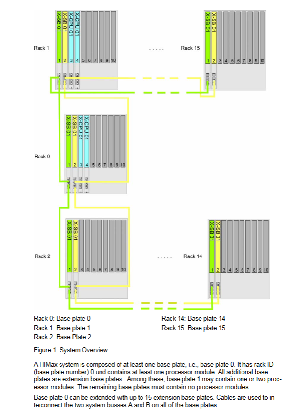
Hardware architecture and module details
(1) Series division and core differences
Features H51X series H41X series
1 basic rack 1
Up to 16 expansion racks and up to 1 expansion rack
The maximum number of I/O modules is 256 and the maximum is 28
The maximum number of I/O points is 4096, and the maximum is 224
The maximum number of communication modules is 10 and the maximum is 2
Applicable scenarios: Large, complex systems, small, and streamlined systems
(2) Core module
Module model, functional key parameters
The F-CPU 01 processor module supports dual redundancy, runs user programs, and manages redundant synchronization
F-IOP 01 I/O processing module connects the system bus and I/O bus, providing I/O watchdog signals
F-COM 01 communication module with 2 Ethernet interfaces and 1 fieldbus interface, supporting security protocols
F-PWR 01 power module 24VDC to 5VDC, single module 10A current
F-PWR 02 buffer module compensates for voltage drop (up to 20ms)
(3) Power Supply and Bus
Power configuration:
Input voltage: 24VDC (-15%~+20%), ripple ≤ 5%, in compliance with SELV/PELV standards;
Redundant power supply: supports dual power input and distributes power through modules such as K 7205/K 7212;
5V power supply: H51X can accommodate up to 5 parallel F-PWRs 01, with a maximum current of 40A; H41X up to 2, maximum 10A current.
Bus design:
System bus: Dual bus (A/B), controlled by processor modules, supporting redundant communication;
I/O bus: connects I/O processing modules and I/O modules to transmit process data;
Connection requirements: The system bus should use Cat. 5e or above industrial network cables, with a minimum wire diameter of 0.2mm ² inside the cabinet and 0.5mm ² outside the cabinet.
Software and core functions
Programming tool: SILworX
Programming method: Supports IEC 61131-3 standards such as Function Block Diagram (FBD);
Variable management: supports global/local/system variables, with initial values that can be set to safe values to avoid risks during failures;
Multi tasking: Up to 32 user programs can run in parallel, supporting priority configuration.
Core functions:
Noise Blanking: The suppression time is calculated based on the safe time and watchdog time, with the maximum suppression time being equal to the safe time minus 2 times the watchdog time;
Event recording: Non volatile cache of 1000 events, distinguishing between short-term (fault) and long-term (user operation) logs;
Online diagnosis: Check module status and fault codes through LED indicator lights (3 flashing frequencies) and SILworX software;
Forcing: Supports global/local forcing, can set time limits, and requires authorization before use.
|Processor redundancy | 1-2 F-CPU 01 modules | Seamless takeover of redundant modules in case of single point failure|
|Redundancy of I/O modules | Grouping of 2 I/O modules of the same type | Automatic switching of channel level faults, requiring installation in different racks|
|System bus redundancy | Dual system bus (A/B) parallel | When a single bus fails, the other bus maintains communication|
|Power redundancy | Dual 24VDC power input | Single power failure does not affect system operation|
Standard communication: Modbus, PROFIBUS DP (some require authorization code);
Connectivity: Up to 5 PADTs can be connected simultaneously, with 1 write permission and 4 read permissions.
Lifecycle and Maintenance
Installation requirements:
Protection level: default IP20, can be upgraded to IP54 as needed (compliant with EN 60204);
Grounding and shielding: Functional grounding enhances EMC performance, cable shielding is connected at both ends to avoid parallel connection with power lines;
Surge/lightning protection: Data lines need to be shielded, and lightning protection devices should be installed in outdoor scenarios.
Start process:
Step: Connect power → Configure rack ID/IP → Load project → Set module mode (Stop → Run) → System startup;
Troubleshooting: When the hardware and configuration do not match, the system enters the STOP/INVALID CONFIGURATION state.
Maintenance points:
Regular verification: Security related applications need to undergo regular verification testing according to the manual;
Component replacement: Fans need to be replaced regularly, and module replacement must comply with ESD protection;
Operating System Upgrade: Supports loading new versions of the operating system through SILworX.
Core positioning and safety features of the product
Core positioning: A modular PES designed specifically for high safety requirements in industrial automation, suitable for safety related control scenarios such as emergency shutdown and process protection, replacing traditional relay logic and enhancing system flexibility and reliability.
Security level and standards:
|Standard | Level/Compliance Requirements|
| IEC 61508 | SIL 3 |
| EN 954-1 | Category 4 |
| ISO 13849-1 | Performance level e |
| EMC | EN 61000-6-2/4 |
|Dangerous environment | Additional measures needed to adapt to Ex Zone|
Core security principles:
By default, it follows the principle of ‘De energy to trip’, and in the event of a fault, the input/output signal automatically switches to a safe power-off state;
Support ‘Energize to trip’, which must meet the requirements of application standards for line diagnosis;
All modules have self detection function, triggering safety response in case of failure (such as redundant switching, system shutdown).
Controller permissions: Level 3 (Read/Read+Write/Administrator), up to 10 users;
Security restrictions: Mandatory operations require authorization and time limits can be set; Overloading operations must meet RUN status and permission requirements.
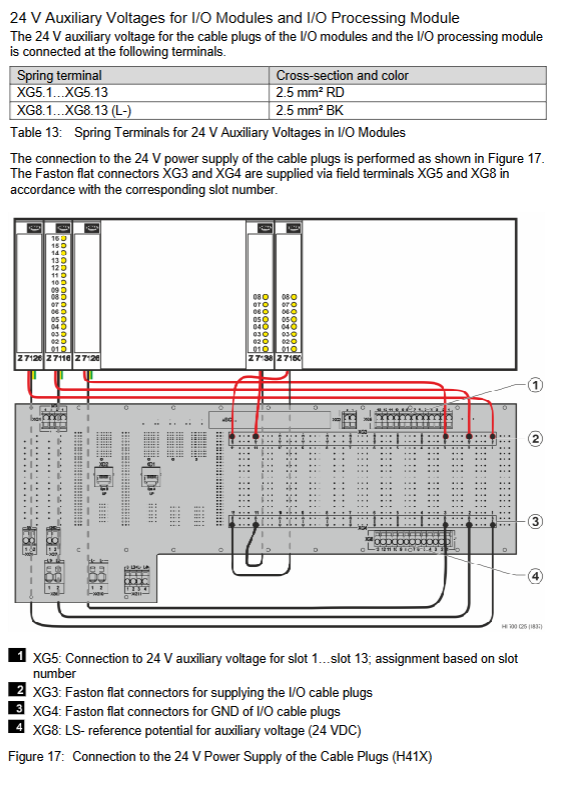
Core positioning: A hard wired safety control system designed specifically for high potential risk automation processes, focusing on ultimate safety and reliability.
Safety level: up to SIL 4 (highest safety integrity level), in compliance with multiple international standards:
Equipment standard: EN 50178:1997 (Electronic equipment for power installation)
EMC standards: EN 61000-6-2:2001 (industrial environment immunity), EN 61000-6-4:2001 (industrial environment emission)
Hazardous environment: EN 60079-15:2003 ATEX (Zone 2, T4)
Core Features:
Integrated design: Each module integrates input, logic processing, and output functions, with a compact structure;
Programming method: No software required, application configuration is achieved through the hard wiring technology of the backplane bus board (soldering, Termipoint, winding);
Redundancy support: All modules can form a redundant structure, significantly improving system availability;
Safety principle: Adopting a “de energize to trip” design to ensure system safety in the event of a malfunction.
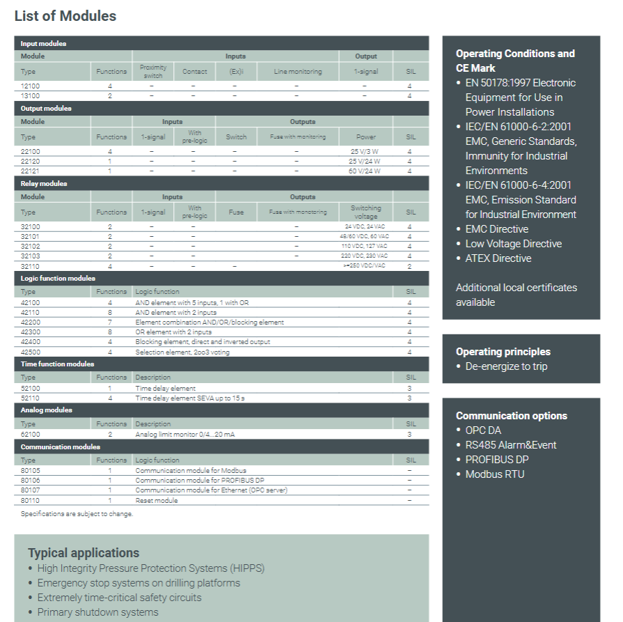
Detailed explanation of the entire series of modules
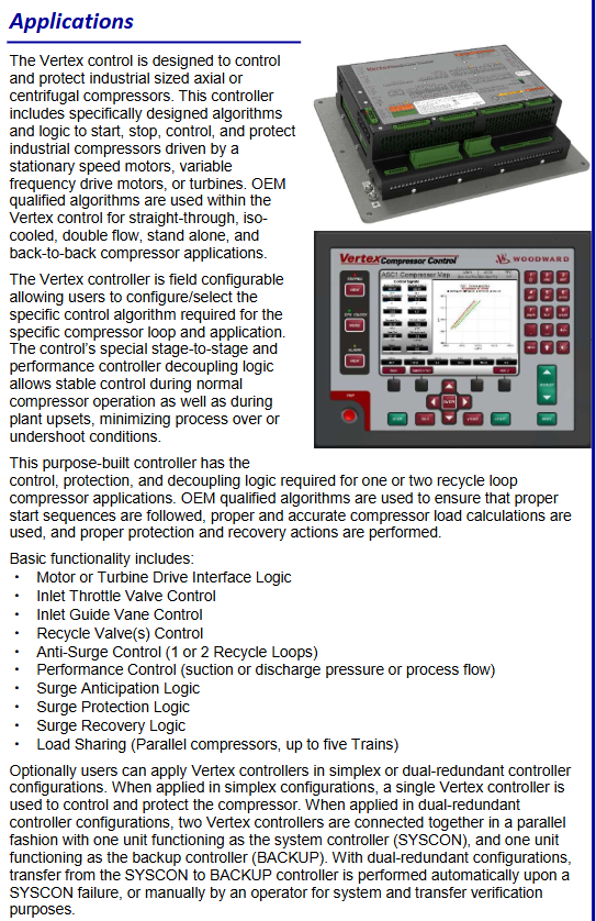
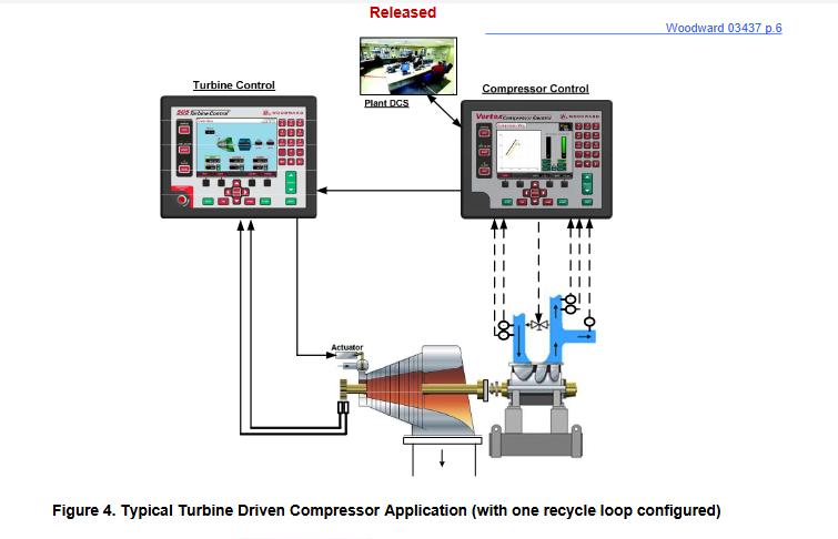
Core positioning: An integrated control and protection system designed specifically for industrial axial/centrifugal compressors, integrating control, performance optimization, and fault protection functions without the need for additional external equipment, reducing system complexity.
Architecture selection:
|Architecture Type | Core Features | Applicable Scenarios|
|Simplex | Single Controller Working Independently | Scenarios with General Continuity Requirements|
|Dual Redundancy | Main Controller (SYSCON)+Backup Controller (ACKUP), automatic fault switching | Critical production process, requiring high availability|
Key advantages:
Integrated design: integrating anti surge, performance control, load distribution, operation panel, and fault indication functions;
On site configurable: supports on-site modification of core functions, minor adjustments can be completed online;
Hazardous environment adaptation: certified by ATEX, CSA, etc., suitable for Class I, Div 2 and other hazardous areas;
Usability: 8-inch graphical panel with first out fault indication for simplified troubleshooting.
Detailed explanation of core functions
(1) Control function
Anti surge control (ASC)
Support 1-2 loop circuits and adapt to complex compressor structures;
Core logic: Early intervention is achieved through Boost backup line and Surge Control Line, with 7 surge detection methods (flow derivative, minimum flow, etc.);
Protection action: When surge occurs, execute Surge Recovery (valve quick opening) and Surge Minimum Position (SMP) to avoid secondary surge.
Performance Control (PFC)
Control objects: compressor suction pressure, discharge pressure, process flow rate, etc;
Auxiliary components: Performance PID+Limiter 1/2 PID (limit protection), sequential Ramp control (valve position during start/blow/stop phases);
Flexible adjustment: Supports remote analog set point (4-20mA).
Load distribution control
Supports up to 5 compressors running in parallel without the need for additional main controller hardware;
Communication method: Realize data synchronization between units through UDP protocol and automatically balance load;
Configuration features: Plug and Play, simplifying deployment.
Other control functions
Independent PID: can be used for independent control circuits such as shaft seal steam and auxiliary processes;
Sequence control: covering the entire process of position control such as starting, blowing, stopping, and zero speed.
(2) Protection function
Fault monitoring and alarm
Key parameter monitoring: bearing temperature, compressor vibration (supporting 4-20mA acceleration sensor), alarm/shutdown threshold can be set;
Equipment fault protection: CPU/memory fault detection, I/O signal fault diagnosis;
Event recording: First out fault indication, recording alarm/shutdown events with timestamps.
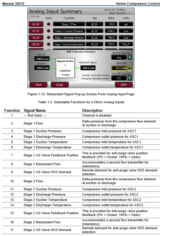
Special input 8-channel RTD signal (RTCNet RTD module)-
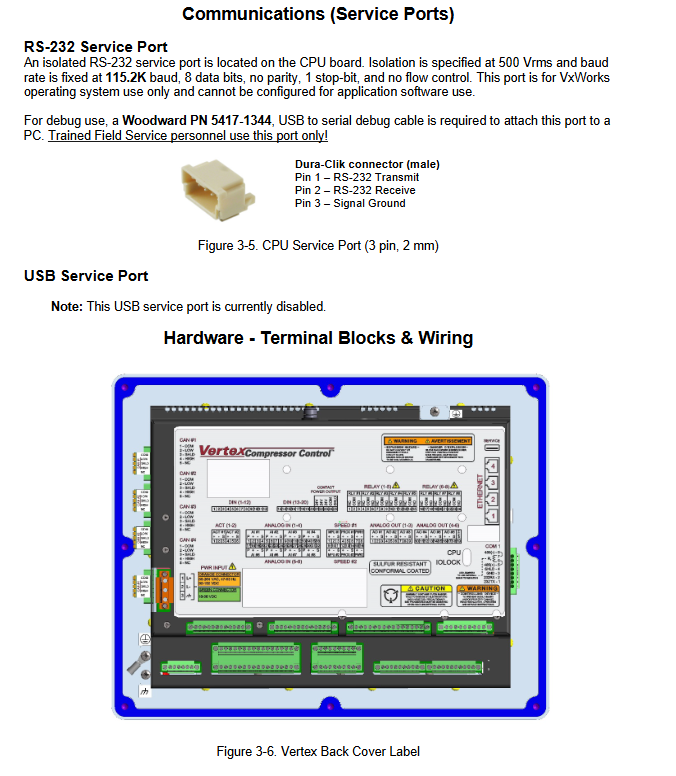
(2) Communication interface
Number and specifications of interface types support protocols/functions
Ethernet single redundancy: 3 customer ports+1 service port; Dual redundancy: 2 customer ports+1 service port Modbus TCP, OPC, SNTP time synchronization
Serial port 1 RS-232/485, ASCII/RTU Modbus
CAN port 4-channel RTCNet protocol, used for distributed I/O expansion
Load allocation communication – UDP protocol (inter unit synchronization)
(3) Extension Module (RTCNet)
Module type, number of functional interfaces
AIO module simulates input/output of 8 AI+2 AO/modules, with a maximum of 2 modules
RTD module temperature signal acquisition 8-channel RTD/module
DI module discrete input extension with 16 DI channels/module
DO module relay output extension with 16 channels of DO/module
Product positioning: A digital control system designed specifically for axial and centrifugal compressors, providing full process control such as anti surge, performance optimization, and load distribution, supporting single compressor or multi compressor linkage scenarios.
Model classification:
|Type | Display Model | No Display Model | Core Differences|
Core objective: When multiple compressors are linked, balance the load and maintain the stability of common process variables (such as manifold pressure).
Key features:
Support range: 2-5 compressors, communicating via Ethernet Port 3/4;
Balance parameters: optional WSPV (surge process variable), speed, actual flow rate;
Master Setpoint Management: Automatically elect Setpoint Master and support manual switching;
Calibration mode: Calibrate output signal (requires Service permission, compressor shutdown);
Operation mode: Normal operation control (Operator and above permissions).
User permissions are divided into four levels: Monitor (read-only), Operator (operation), Service (maintenance), and Configure (configuration). Passwords are distinguished by default (Configure: wg1113).
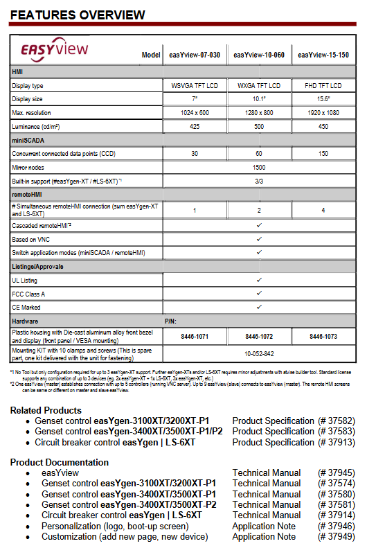
Product positioning: A miniSCADA visualization solution designed specifically for Woodward power management controller controlled generator set fleet. As a ready-made HMI option, it meets the safety remote control, monitoring, and visualization needs of users such as switchgear manufacturers and generator set packagers.
Core advantages:
No need for extensive on-site engineering work, pre-set equipment connections and data structures
Balancing indoor and outdoor use, with a wide operating temperature range, IP66 protection, anti glare treatment, and high brightness display
Support brand personalization, replaceable logo and startup screen
Applicable scenarios: hospitals, data centers, offshore drilling platforms, landfills, leased equipment, wastewater biogas power generation, etc.
Comparison of Model and Key Parameters
Model easyYview-07-030 easyYview-10-060 easyYview-15-150
Preset support: Data structure for 3 easyYgen XT+3 LS-6XT devices, a total of 6 devices
Core purpose: System level performance visualization, suitable for viewing high-frequency/commonly used values during routine operation and maintenance
Scalability: Can be achieved through atvisa ® Tools for adding third-party devices, adjusting single line diagrams, etc
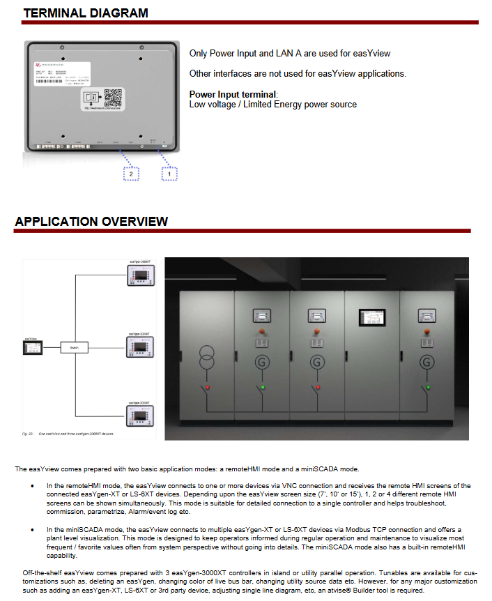
Remote HMI mode:
Connection method: Connect to a single controller through VNC
Display capability: Simultaneously display 1/2/4 different remote HMI screens based on screen size
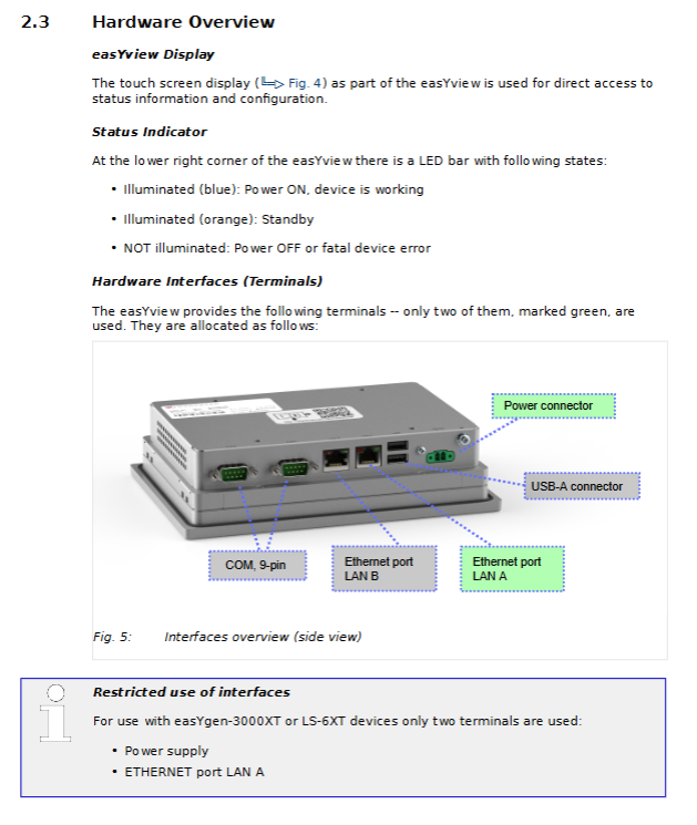
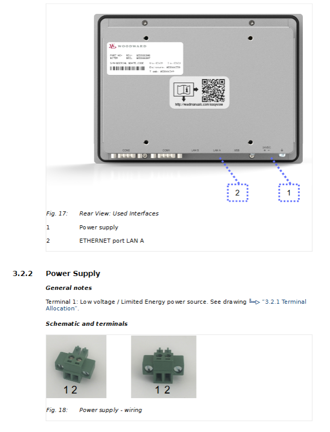
Interface: Only uses power input and LAN A Ethernet interface, other interfaces are not used for easyYview applications
Installation method: Front panel installation and VESA 100 × 100mm installation, including installation kit with 10 fixtures and screws (part number 10-052-842)
software configuration
Operating System: Linux
Application software: atvisa for miniSCADA mode ®, Remote HMI mode using VNC
Customization and Support
Customization related
Basic customization: achieved through tuning parameters and online keyboard (such as deleting easyYgen, changing bus color, etc.)
Deep customization: using atvisa ® SCADA tool (please refer to application note AN # 37949)
Brand personalization: replaceable logo and startup screen (please refer to application note AN # 37946)
Related products and documents
|Product Type | Product Name | Product Specification Number | Technical Manual Number|
|Generator set control | easyYgen-3100XT/3200XT-P1 | 37582 | 37574|
|Generator set control | easyYgen-3400XT/3500XT-P1/P2 | 37583 | 37580/37581|
Product positioning: Provide remote control, monitoring, and visualization HMI solutions for switchgear manufacturers, generator set packaging companies, and others
Model classification: Three core models, with the following key parameters:
|Model | Screen size | Maximum number of connected devices (mini SCADA) | Resolution | Weight|
|EasyYview-07-030 | 7 inches | 3 units | 1024 × 600 | Approximately 2kg|
|EasyYview-10-150 | 10.1 inches | 18 units | 1280 × 800 | Approximately 3.9kg|
|EasyYview-15-150 | 15.6 inches | 18 units | 1920 × 1080 | Approximately 6.9kg|
Applicable scenarios: hospitals, data centers, offshore drilling platforms, landfill sites, biogas power generation, etc
Core functions and working modes
working mode
Remote HMI mode: Connect 1 easyYgen-3000XT/LS-6XT via VNC technology, supporting simultaneous display of 1-4 screens (7-inch 1 screen, 10 inch 2 screens, 15 inch/PC 4 screens)
Mini SCADA mode: connects multiple devices through Modbus/TCP protocol, provides system level visualization, and supports customized topology
Key Features
Support device cascading: Master/Slave configuration, enabling multiple easyYviews to share remote screens
Personalized customization: can modify logo, adjust bus color, configure main power data source, etc
Safety protection: IP66 dustproof and waterproof (front), in compliance with UL, CE and other certification standards
Installation and Configuration
Installation requirements
Installation personnel: must be qualified electricians and comply with 5 electrical safety rules
Connection interface: Only use LAN A Ethernet port and 24V DC power interface (± 20% voltage fluctuation)
configuration process
First setup: Connect to the network → Configure IP address (same subnet) → Select working mode → Set password (default user/user, recommended to modify)
Mode switching: Select mini SCADA/Remote HMI through the settings page, click “Apply” to take effect
Device connection: Mini SCADA mode requires configuration of Modbus slave ID (parameter 3188) and protocol (5016)
Technical specifications
Hardware specifications
Processor: NXP ARM Cortex-A53 i.MX 8M Mini (4-core 1.6GHz)
|The screen is black but the blue LED is on | Display malfunction | Contact Woodward service partner|
|Mini SCADA page element flashing yellow | Device connection failure | Check IP address and Modbus configuration|
|CCD exceeded! “Pop-up window | Number of data connections exceeded | Switch to PC mode and close unnecessary browsers|
|Remote connection interruption | Network conflict or VNC port occupation | Check for IP conflicts and release occupied ports|
Safety Rules
Unauthorized personnel are prohibited from operating or modifying the equipment
Cut off the power before operation to avoid electrostatic discharge
Prohibit the use of non certified spare parts or unauthorized modification of equipment
Key issue
Question: What is the core difference between the two working modes of the easyYview series (Remote HMI and mini SCADA)?
Answer: The core difference lies in the connection method and application scenario. Remote HMI mode connects one easyYgen-3000XT/LS-6XT through VNC technology, focusing on detailed control and parameter viewing of a single device; The mini SCADA mode connects multiple devices (up to 3 for 7-inch and up to 18 for 10/15 inch) through Modbus/TCP protocol, focusing on system level overall monitoring and topology visualization, and supporting parallel status display of multiple devices.
Question: What are the key requirements to pay attention to when installing the easyYview device?
Answer: Three core requirements need to be considered. One is personnel qualification, which must be operated by qualified electricians and comply with electrical safety rules; The second is hardware connection, using only LAN A Ethernet port and 24V DC power interface to avoid electrostatic discharge; The third is the installation size, which needs to be drilled according to the corresponding model (such as 192.4 × 139.0mm for 7 inches), and after tightening, ensure the IP66 protection level.
Question: What are the possible causes and solutions when the “CCD exceeded!” pop-up appears in easyYview?
Answer: The reason is that the number of data connections (CCD) in mini SCADA mode exceeds the license limit, mostly due to opening the visualization page in both easyYview and PC browser simultaneously. Solution: One is to switch to PC mode on easyYview (only using 1 CCD); Secondly, close any unnecessary browsers on the PC or refresh the page to reconnect; Thirdly, if the issue persists, close the PC browser and restart the easyYview device.
-Core features: Hot swappable (continuous power replacement), high isolation between channels, partially “smart modules” (with built-in microcontroller, self diagnosis+online calibration)
-Timestamp: 1ms resolution for discrete I/O events, 5ms resolution for analog I/O and software variables
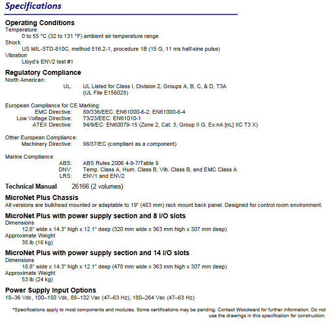
(2) Environment and Certification
Category specific parameters
The working environment temperature is 0-55 ° C (32-131 ° F), the vibration complies with Lloyd’s ENV2 standard, and the impact complies with US MIL-STD-810C (15G, 11ms half sine pulse)
Compliance Certification – North America: UL Class I Division 2 (Groups A/B/C/D, T3A)
-Europe: CE (EMC/Low Voltage/ATEX Directive) ATEX Zone 2(Cat.3,Group II G)
-Ship: ABS Rules 2006、DNV(Temp Class A/Hum Class B/Vib Class B/EMC Class A)、LRS(ENV1/ENV2)
Core functions and software
(1) Control and programming functions
Detailed description of functional categories
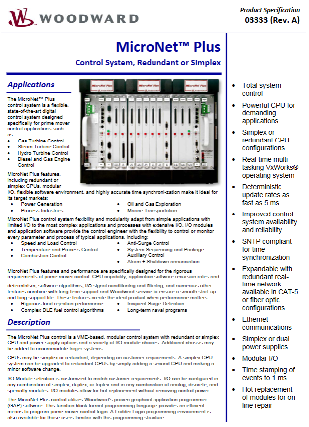
Core control capabilities include speed/load control, anti surge control, combustion control, temperature/process control, system sequence control, auxiliary equipment control, alarm/shutdown annunitor
-Simulation: NetSim ™ Simulation environment, compatible with process model testing programs, reducing debugging time
-Operating System: VxWorks ® Real time system, supporting multiple rate groups (up to 5ms critical control loop, slow rate group adapted to non critical logic)
Key feature – Certainty: Control logic execution is not affected by program load or code modifications, and dynamic performance is predictable
-Time synchronization: SNTPv4 compatible, synchronization error with external time sources<1ms
(2) Communication and Expansion Capability
Category specific parameters
Supports Ethernet protocol TCP/IP、UDP/IP、OPC DA 3.0/AE 1.0、Ethernet Global Data(EGD)、Modbus RTU/ASCII( Ethernet/serial port) CANopen、 Customize proprietary drivers
Scalability – Chassis Expansion: The host chassis can connect up to 7 expansion chassis through real-time network, supporting fiber optic communication (up to 2km)
-Distributed I/O: Compatible with Woodward LinkNet ® Module and third-party CANopen/Ethernet/serial port distributed I/O
Service tools Control Assistant (03201), Monitor GAP (03306), support data graphic display, logging, trend analysis, event recording, X-Y plotting
System advantages and value
High reliability: redundant CPU/power supply, module self diagnosis, online calibration, suitable for key prime mover control scenarios
Flexibility: Modular I/O combination, multiple programming methods, multi protocol communication, seamless adaptation from simple to complex scenarios
Maintainability: Hot swappable modules, remote diagnostics, simulation testing, reducing downtime and debugging costs
Real time performance: fastest 5ms control loop, 1ms event timestamp, meeting the high-precision control requirements of the prime mover