Installation Guide for GE Hydran M2 Transformer Gas
Product Overview
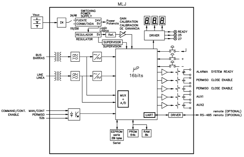
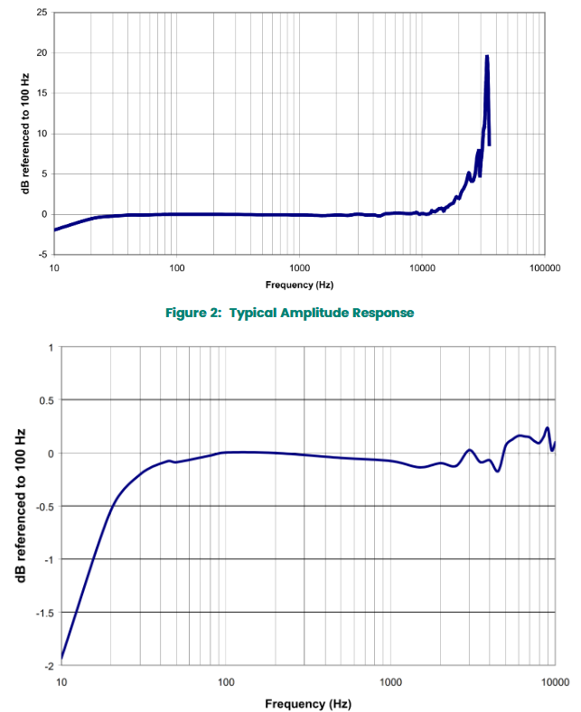
Hydran M2 is a transformer gas monitoring system launched by GE Energy, which is used to monitor the gas content (such as hydrogen) and humidity level in transformer oil in real time. By analyzing changes in gas concentration, the operating status of transformers can be determined, and potential faults (such as insulation aging, partial discharge, etc.) can be warned in a timely manner. The system supports network communication and can be connected to the monitoring center, suitable for online monitoring of various types of power transformers.
Safety Warning and Precautions
General safety requirements
Installation and maintenance must be carried out by qualified professionals, and the power station operator must be notified before operation to avoid triggering false alarms due to parameter modifications, power outages, etc.
The power cable needs to use a 2.08 mm ² (14-AWG) specification, with a maximum distance of 15 meters (50 feet) from the power source, and equipped with overcurrent protection.
Do not touch the sensor membrane, block the breathing hole, or puncture the breathing hole membrane to avoid damage to the sensor.
When installing, it should be placed horizontally, and tilting, vertical installation, or using bends are prohibited. Avoid installing on the inlet side of the radiator pump, bends, or accessory boxes.
Do not use high-pressure water flow to rinse equipment, spray paint, or clean sensors with solvents to avoid affecting monitoring accuracy or damaging equipment.
Multi language security warning
The manual is annotated with safety warnings in six languages: English, French, Spanish, German, Italian, and Swedish, emphasizing that unauthorized operations may result in equipment damage, property damage, or personal injury.
Installation process
1. Installation preparation
Tool preparation: GE provides tools including 3/16 inch hex wrenches, 1/16 inch and 5-32 inch hex L-shaped wrenches, wrenches, PTFE tape, etc; The installer needs to bring their own screwdriver, adjustable wrench, wire stripping pliers, water bucket, and cloth, etc.
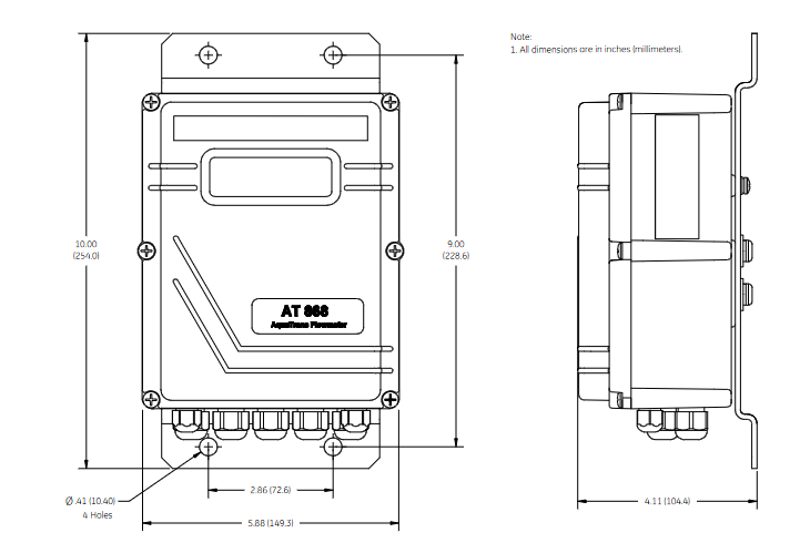
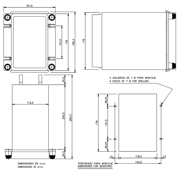
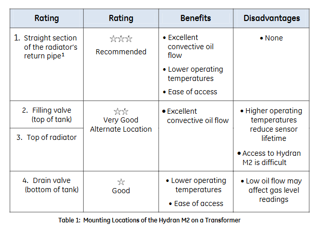
Installation location selection: It is recommended to install on the straight section of the radiator return pipe (with good convective oil flow, low temperature, and easy maintenance). Alternative locations include the top oil injection valve, radiator top, and bottom drain valve (note the impact of oil flow on readings). During installation, it is necessary to ensure that the bottom clearance meets the requirements (84 mm space, see Figure 11).
2. Sensor installation
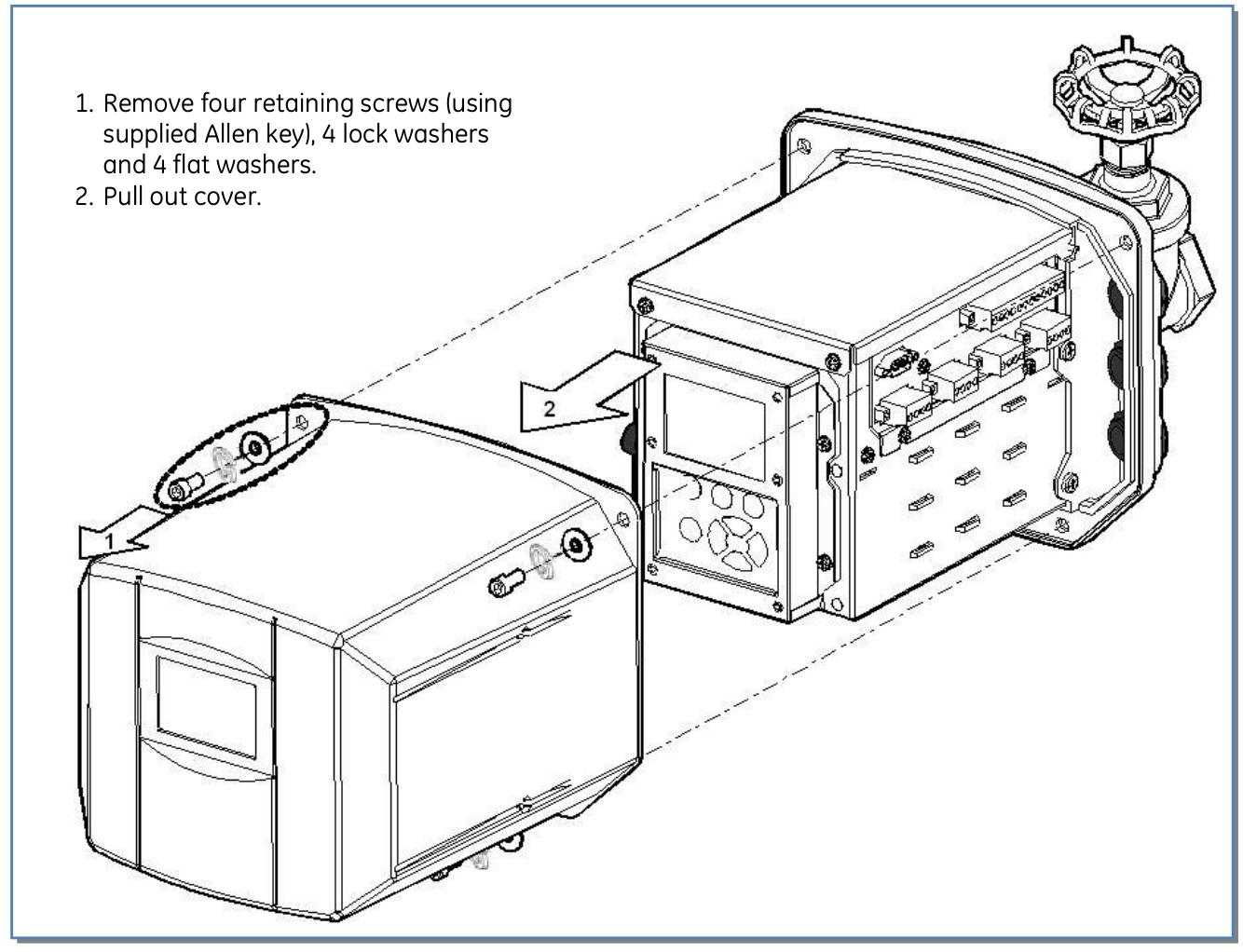
Separate the sensor from the housing: Remove the fixing screws and clips, carefully pull out the sensor, and disconnect the sensor cable (rotate the connector 1/8 turn and pull out).
Sensor sealing: Wrap PTFE tape around the sensor thread, manually install the sensor onto the valve, and tighten it with an adjustable wrench.
Exhaust operation: Ensure that the air release screw is located at the 12 o’clock position, slowly open the valve, exhaust the air inside the sensor (collect the oil into the water bucket), then tighten the air release screw and clean the residual oil.
Connecting the casing: Insert the sensor cable connector into the sensor, rotate and fix it, push the casing onto the sensor (to avoid squeezing the cable), install the clip and tighten the fixing screw.
Grounding treatment: Use 10-6 AWG copper wire to connect the housing grounding terminal to the grounding electrode.
3. Cable installation and wiring
Cable conduit: Install waterproof conduit fittings (1/2 inch NPT, PG-13, or M20), metal conduit must be grounded, and unused openings must be sealed.
Wiring terminals:
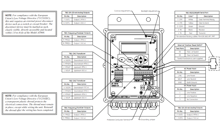
Analog input: Supports self powered, two-wire/three wire loop power supply sensors, connected according to terminal identification (see Figure 23-26).
Analog output: 4-20 mA or 0-1 mA output, connected to SCADA system (see Figure 27-29).
Alarm relays: 5 SPDT relays configured with software, corresponding to normally open, normally closed, and common terminals (see Figure 30).
Power supply: The AC power supply needs to be connected to the live wire (L), neutral wire (N), and ground wire (ground terminal), and equipped with a fuse holder (see Figure 31).
4、 Software configuration
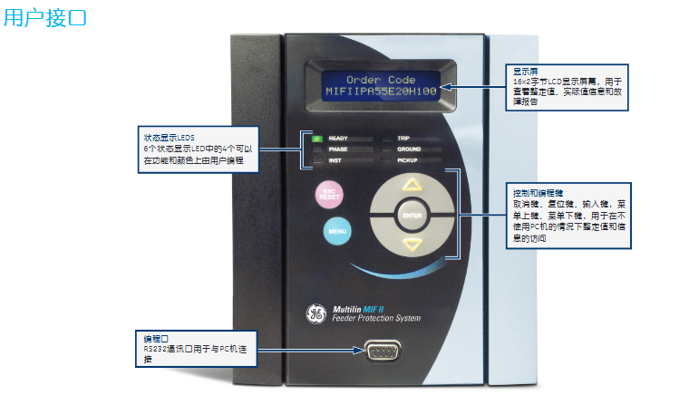
User interface operation
Configure through the LCD display screen and buttons (Esc, Enter, directional keys, function keys), with menus including alarm settings, reading viewing, system settings, testing, service, etc. (see Figure 32-33).
Key parameter settings
Date and Time: Set in “Setup → Date&Time” to ensure time synchronization.
Sensor test: Execute in “Service → Gas Sensor Test” and there is no reading within 2 minutes after the test.
Shutdown process: It is recommended to exit all programs first, run “Backup” to save settings, and then restart or disconnect the power to avoid data loss.
Hardware and Interface
1. Core hardware configuration
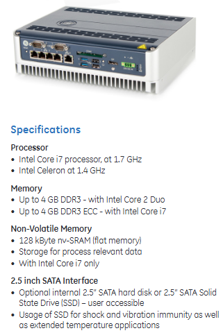
Processor: Intel XScale PXA255 300 MHz.
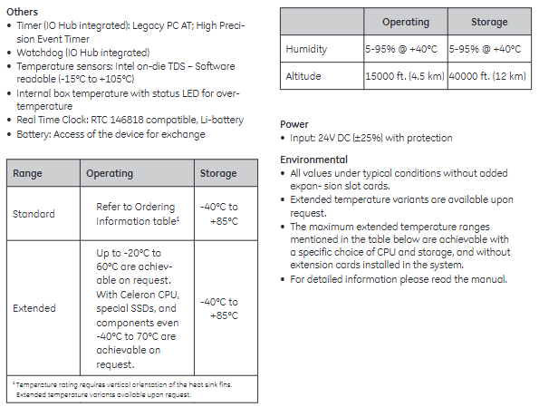
Memory: 32 MB DRAM (divided into system, program, and storage memory), 32 MB Flash storage (including operating system and user program areas), 512 KB battery backup SRAM (data power off reserved).
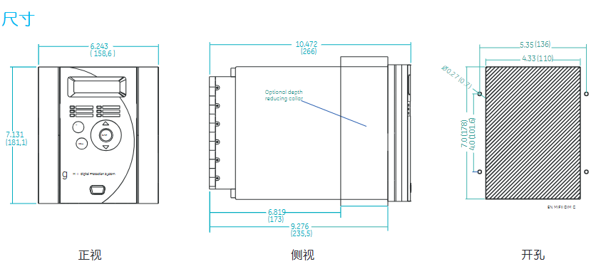
Display:
10 “monochrome model: 640 × 480 resolution, 256 levels of grayscale, passive display.
12 “model: 800 × 600 resolution, color model supports 32768 colors, monochrome model supports 256 levels of grayscale, both are TFT active displays.
Touch screen: resistive, 12 bit resolution, supports stylus or finger operation, requires calibration to ensure accuracy.
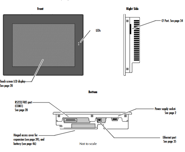
2. Interfaces and extensions
Communication interface:
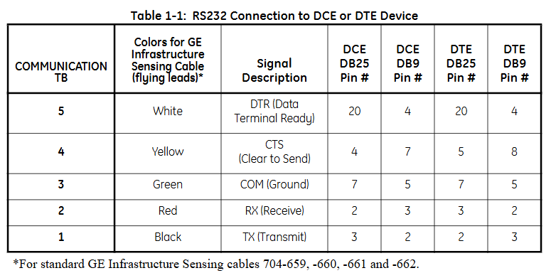
COM1: DB25 female interface, supporting EIA232 C/EIA485 standard, with a maximum speed of 115200 bps, can be used for serial communication or terminal simulation.
Ethernet: RJ45 interface, supports 10/100BaseT adaptation, includes 2 status LEDs, supports TCP/IP protocol and network connection.
CF card slot: Supports Type II Compact Flash cards, expandable storage or adding functional modules (such as wireless network cards).
Expansion bus: Built in expansion slot, supports optional expansion modules (requires opening the back cover for installation).
Other interfaces: 4 external USB 2.0 ports, 1 internal USB port, VGA display interface (12 “model including Display Port).
Software and Operations
1. Operating system and core functions
Operating System: Windows CE. NET 4.1, supports 32-bit applications, compatible with Windows series operating logic, simplifies development and operation.
Key tools:
Backup: Save the registry and desktop settings to Flash to ensure that the configuration is not lost after power failure.
Storage Manager: Manage storage devices (CF cards SRAM), Support repair or formatting.
System Information: Display device hardware, system version, and other information to assist in troubleshooting.
Pocket Internet Explorer: Browse web pages, supports JavaScript, can configure proxy servers and dial-up connections.
2. Network and Communication Configuration
IP address setting: Supports DHCP automatic acquisition or manual configuration, which needs to be set through “Network and Dial up Connections”.
Windows network access: Device name, user information, and domain need to be configured to access network shared resources through Windows CE Explorer.