Call us 24/7uaedcs@163.com
Welcome to the official website of CNIACS Automation Technology Co., Ltd!
Call us 24/7uaedcs@163.com

GE VMIVME-5565 Ultra High Speed Fiber Reflective Memory

Product Overview

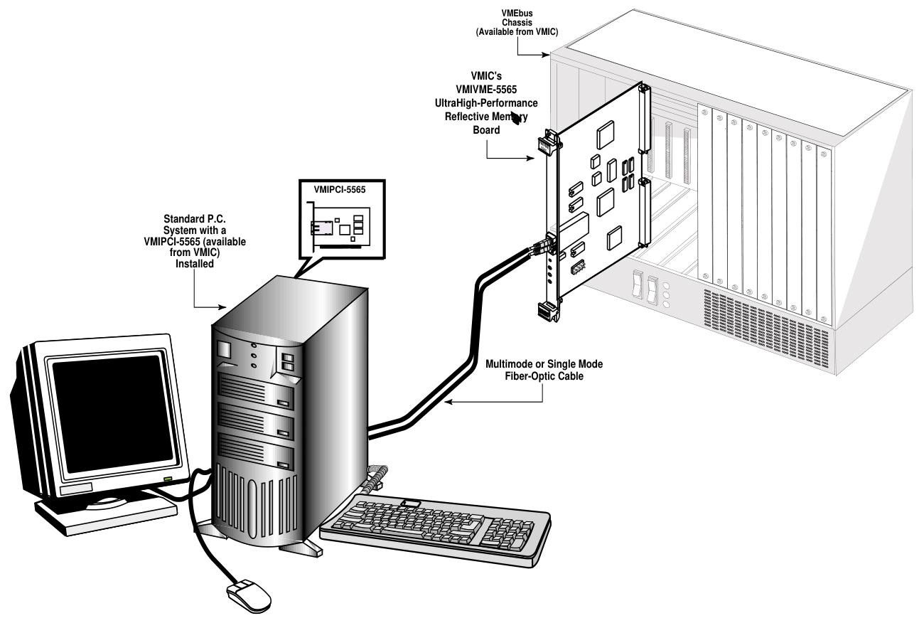
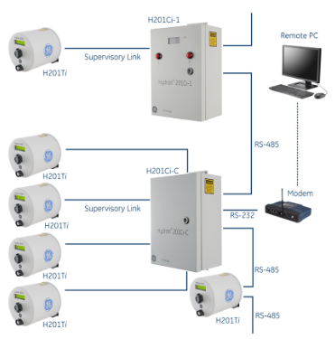
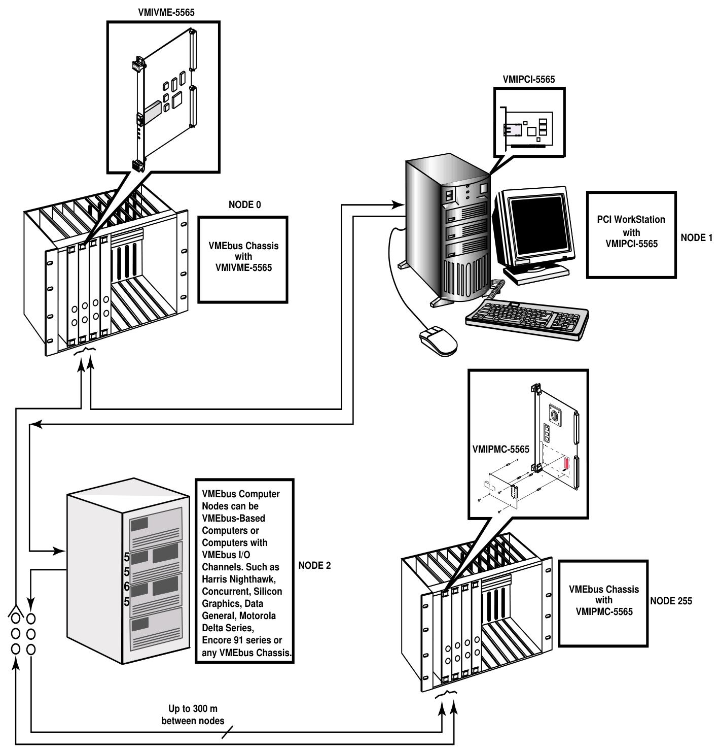
VMIVME-5565 is a member of the VMIC Reflective Memory Real time Fiber Network product series based on VMEbus. It adopts a standard 6U European card shape and can be integrated with VMIMPC-5565 and VMIPCI-5565 of the same series into networks using standard fiber optic cables. Each card in the network is called a node. It enables computers, workstations, PLCs, and other embedded controllers with different architectures and operating systems to share data in real time, with convenient operation. Data is transmitted through written memory (SDRAM), and the onboard circuit automatically transfers the data to all other nodes, almost without the involvement of any host processor or system.

Core Features

A high-speed and easy-to-use fiber optic network with a serial rate of 2.12 Gbaud.

Supports up to 256 nodes.

When using multimode fiber, the connection distance can reach 300 meters, and single-mode fiber can reach 10 kilometers.

Dynamic packet size, with each packet containing 4 to 64 bytes of data.

The transmission rate varies depending on the packet size, with 43 Mbytes/sec for 4-byte packets and 174 Mbytes/sec for 64 byte packets.

Up to 128 Mbyte of SDRAM reflective memory with parity check.

Supports VMEbus DMA.

Four universal network interrupts, each with 32-bit data.

Equipped with error detection function.

Standardize compliance

Compliant with the VMEbus specification (ANSI/IEEE STD 1014-1987, IEC 821 and 297), with the relevant mnemonics A32: A24; D32/D16/D08 (EO): Slave: 39/3D:09/0D。

Working principle

Basic operation: Each node in the network is interconnected in a daisy chain loop through fiber optic cables. The data transmission is initiated by the VMEbus host system writing to the onboard SDRAM. During the writing process, the onboard circuit automatically writes the data and related information into the transmit FIFO, which then forms variable length data packets ranging from 4 to 64 bytes. These packets are transmitted through the fiber optic interface to the receiver of the next board. After receiving, the relevant circuit opens the data packet and stores it in the receiving FIFO, then writes it to the corresponding position of the local onboard SDRAM, and routes the data to its own sending FIFO. This process is repeated until the data returns to the source node and is removed.

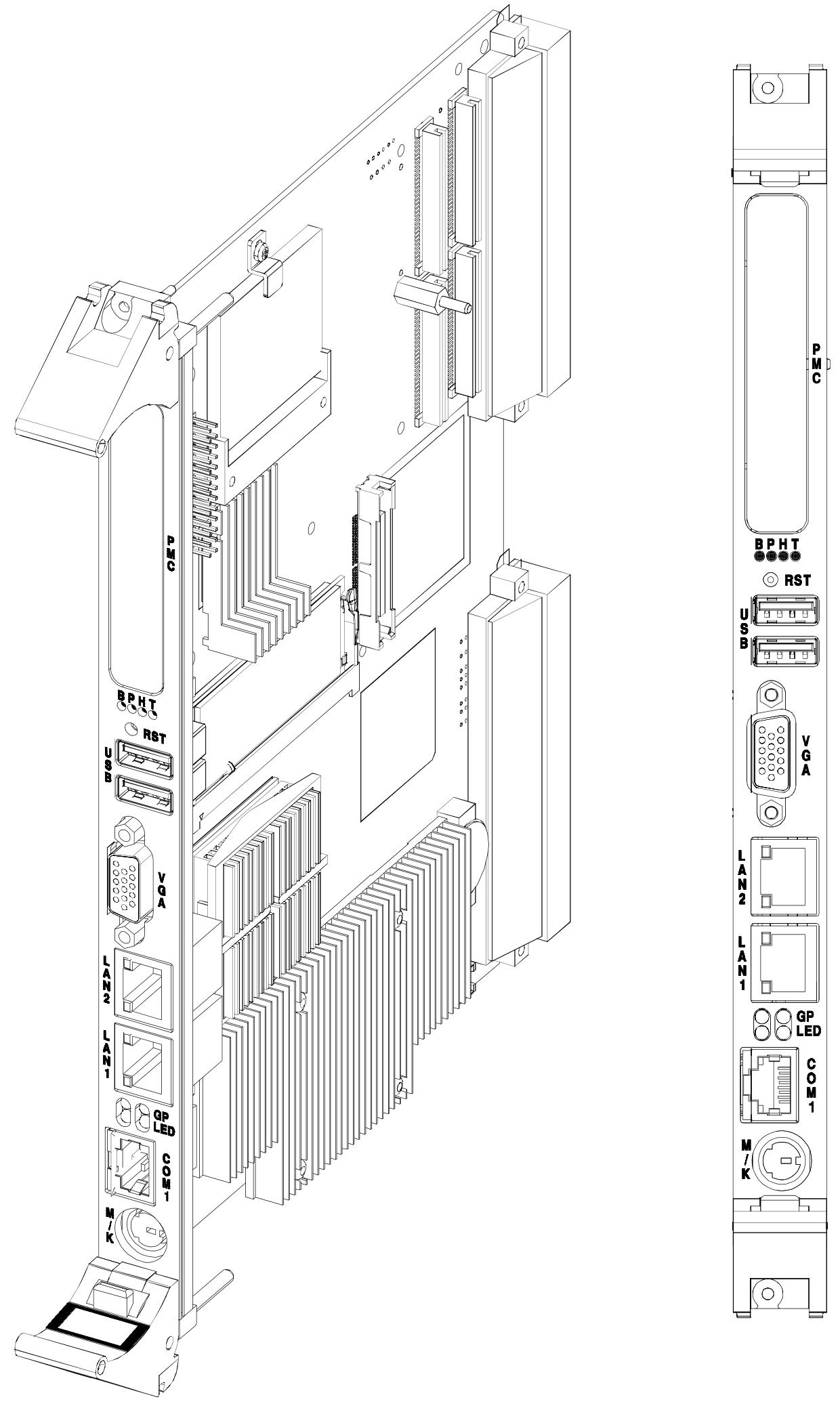
Front panel LED indicator lights: There are three LED indicator lights, with the bottom red being the status indicator light. When powered on, it defaults to “ON” and the status can be switched by writing to bit 31 of the control and status registers; The yellow color in the middle is the signal detection indicator light, which is “ON” when the receiver detects light; The green light at the top is the self data indicator light, which is “ON” when detecting the return of self data.

Register group: including Universe II registers (specific control and status and DMA control registers located in the VMEbus bridge, byte order in small end mode) and Reflective Memory (RFM) control and status registers (implementing unique features of the 5565 series reflective memory board).

Reflective memory RAM: available in two sizes of 64 Mbytes or 128 Mbytes, with parity check function. The parity check function is not enabled when powered on and needs to be enabled through a specific bit setting. When enabled, only 32-bit or 64 bit writes are allowed.

Interrupt circuit: There is a programmable VMEbus interrupt output, and the interrupt source can be separately enabled and monitored through the local interrupt status register (LISR) and local interrupt enable register (LIER).

Network Interruption: capable of transmitting interrupt packets on the network, which can be directed to specific nodes or broadcasted to all nodes, including sender node ID, destination node ID, interrupt type information, and 32-bit user-defined data. The receiving node will store the relevant information in the corresponding FIFO.

Redundant transmission mode: configured through jumper E5, each data packet is transmitted twice in redundant mode, and the receiving node evaluates the transmission situation. Although this mode reduces the probability of data loss, it will lower the effective network transmission rate.

Abnormal packet removal operation: Abnormal packets refer to packets that do not belong to any node in the network. VMIVME-5565 can work as one of the two abnormal master nodes. When an abnormal packet is detected, it will be removed from the ring and relevant flag bits will be set.

Byte order: Due to the tradition of different microprocessor manufacturers, there is a distinction between big endian and small endian. The PCI to VMEbus interface of VMIVME-5565 uses Intel or equivalent bridge chips, adopts small endian byte order, and the interface has external byte order conversion logic, which can achieve independent master/slave hardware byte order conversion.

Configuration and Installation

Unpacking program: Components may be sensitive to electrostatic discharge, so attention should be paid when handling them. After unpacking, check for any damage.

Switch/jumper configuration and position

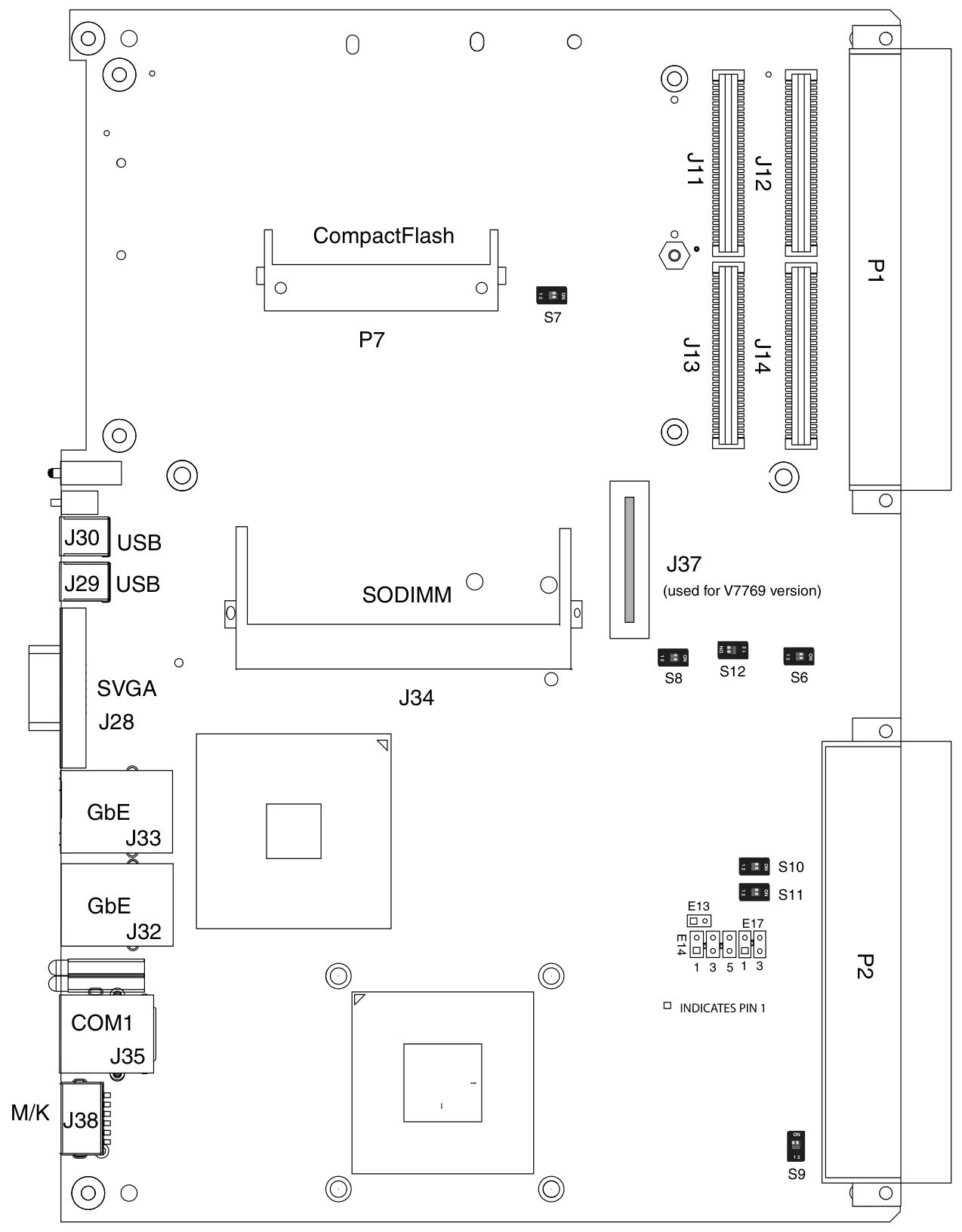
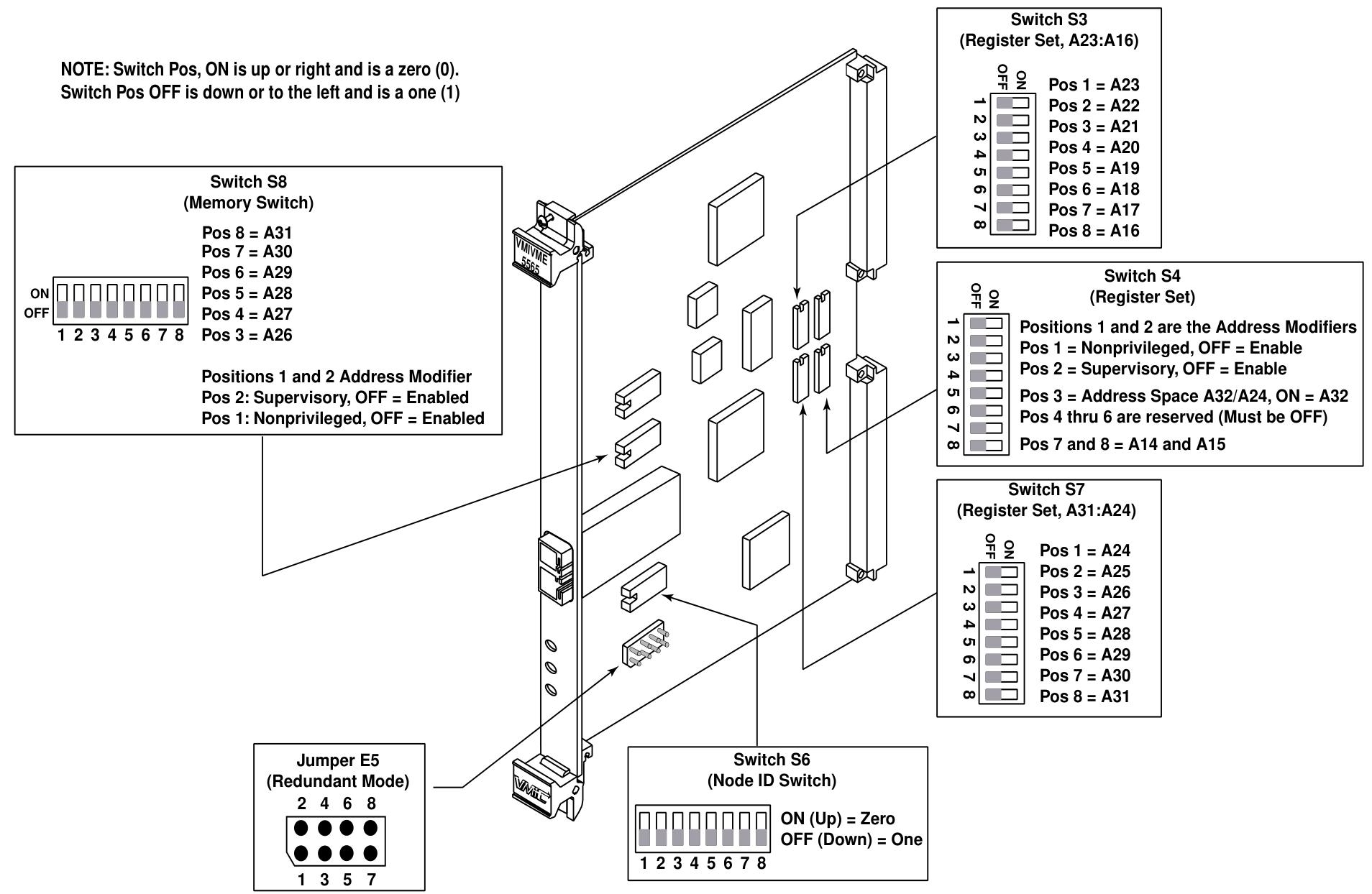
Node ID Switch (S6): An 8-bit switch that sets the node ID within the range of 0 to 255. Each node ID must be unique, and the switch position “ON” corresponds to 0, while “OFF” corresponds to 1.

Jumper E5 (redundant mode configuration): Used to configure redundant or non redundant transmission modes and select abnormal master nodes, with different pin hopping states corresponding to different functions.

Register and memory configuration switch: VMIVME-5565 occupies two independent address spaces on VMEbus. The control and status register spaces can be set as extended address space (A32) or standard address space (A24), and the SDRAM memory space can be set as extended address space (A32). When configuring, address overlap should be avoided. The switch “ON” corresponds to address bit 0, and “OFF” corresponds to address bit 1.

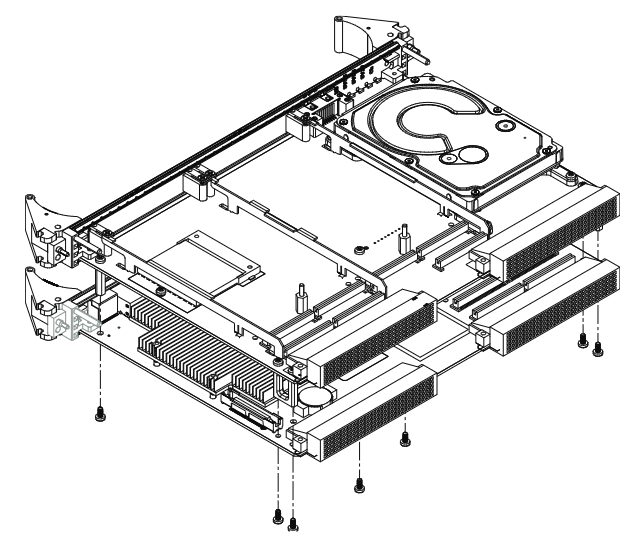
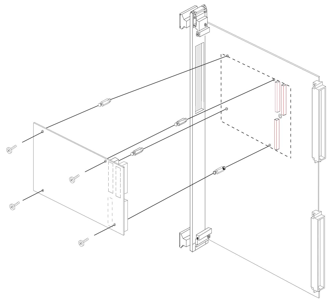
Physical installation: Power off installation, ensure correct switch settings, fix after installation on the chassis, and connect fiber optic cables according to the ring topology.

Front panel description: Optical transceiver, “RX” for receiver, “TX” for transmitter, using “LC” type fiber optic cable, with three LED indicator lights as described earlier. When operating, pay attention to dust prevention and avoid looking directly at the transmitter.

Cable configuration: There are multi-mode or single mode fiber optic interfaces, and cables and connectors have specific specifications.

Connectivity: Nodes are connected in a circular manner.

Programming

RFM Control and Status Register: Located at a specific offset address, it includes local control and status registers, local interrupt status registers, local interrupt enable registers, etc. Each register has different functions and bit definitions.

RFM network registers: including Network Target Data Register (NTD), Network Target Node Register (NTN), Network Interrupt Command Register (NIC), as well as various interrupt sender IDs and data FIFOs, used for generating and receiving network interrupts.

Example of network interrupt handling: including the steps for setting interrupt programs and serving network interrupts.

Universe II registers: divided into Universe II control and status registers and Universe II DMA registers, each with different offset addresses, functions, and bit definitions, which can be used to control and monitor interrupts and DMA transfers.

DMA source and destination addresses: determined by specific registers, transfer direction determined by L2V bits, alignment requirements for addresses, adjustable transfer size and data width, DMA command packet pointer pointing to command packet, DMA startup, VMEbus ownership, completion, and termination all have corresponding operations and mechanisms.

GE VMIVME-3122 High Performance 16 Bit Analog

Product Overview

VMIVME-3122 is a high-performance 16 bit analog-to-digital converter that supports 64 differential or single ended wide range (± 250 mV to ± 10 V) analog inputs, suitable for fields such as factory automation and instrumentation, process control, laboratory instruments, machine monitoring, and data acquisition.

Core Features

Input and Conversion Performance

Supports 64, 32, or 16 differential or single ended inputs, depending on the selected option.

16 bit A/D conversion, software selectable conversion rate, high-performance option up to 100 kSPS, standard performance option up to 50 kSPS.

The software has programmable gains of 1 and 10, which can be fixed for all channels or individually programmed for each channel.

Jumper selectable A/D range: 0 to+5 V, 0 to+10 V, ± 2.5 V, ± 5 V, and ± 10 V.

Scanning and triggering mode

Scan modes: including AutoScan (default, continuously scans all active channels in order), Single Scan (starts a scan of all selected channels once triggered by trigger mode, stops waiting for the next trigger after completion), Random Access (selects, digitizes, and stores a single channel each time the trigger mode is enabled).

Trigger modes: There are Software Trigger (which starts the selected scanning mode by writing the software trigger address), External Trigger (which starts the selected scanning mode by receiving an external trigger through the P2 connector), and Interval Timer Trigger (which starts the selected scanning mode every time the programming time interval expires).

Data storage and access: 1024 word data buffer (16 word deep buffer x 64 channels), dual port register allows VMEbus to access and read the latest stored data at any time, buffer size and block size can be controlled through configuration control registers (CCR).

Other functions

Programmable VMEbus interrupt, which can generate interrupt requests at the end of buffer scanning or during the collection of a specific number of samples.

User programmable interval timer, with a timing interval of up to 687 seconds.

Optional low-pass filter, input with overvoltage protection.

When powered on, it starts in automatic scanning mode with a gain of 1.

Ordering Options

Input filter options (A): 0 for no filter, 1 for 10 Hz (-3 dB), 2 for 50 Hz (-3 dB), 3 for 100 Hz (-3 dB), 4 for 500 Hz (-3 dB).

Channel quantity options (B): 0 is 64 channel high-performance, 1 is 32 channel high-performance, 2 is 16 channel high-performance, 3 is 64 channel standard performance, 4 is 32 channel standard performance, and 5 is 16 channel standard performance.

Input options (C): 0 is a differential analog input channel with a 96 pin non latch connector, 1 is a single ended analog input channel with a 96 pin non latch connector, 2 is a differential analog input channel with a 64 pin latch connector, and 3 is a single ended analog input channel with a 64 pin latch connector.

Functional feature details

VMEbus related

The address modifier response can be jumper selected as A32, A24, or A16 address space, as well as monitoring or user privileges, or both.

Compliant with VMEbus standard ANSI/IEEE STD 1014-1987 IEC 821 and 297.

Reset operation: When the system is reset or the software reset address is written, a board reset occurs. The reset operation automatically establishes default conditions, including automatic scanning mode, channel block size and data buffer determined by the selected option, gain of 1, and conversion rate of 100 kHz (the standard performance option needs to be set to 50 kSPS or lower after reset). After reset, the ADC will undergo a calibration cycle of 41 ms.

Panel indicator: The front panel LED controlled by the program lights up during the reset period and goes off through CSR.

Input characteristics

Accuracy: The maximum error is ± 0.005% reading ± 0.005% range ± 100 µ V.

Stability: Temperature drift is ± 10 PPM (ADC reading)+± 7.5 PPM (ADC range)+± 2.5 µ V, doubling the frequency in single ended applications.

Common mode/floating input protection: In the high-performance option, the low end of each input is grounded through a 22 M resistor; In the standard performance options, users must control the common mode voltage to prevent input fluctuations.

Input noise: (0.4+0.3/G) mV, where G is the PGA gain, noise is independent of filter options.

Other: The maximum input bias current is 40 nA (at zero input), and the minimum input impedance is 5 M Ω (parallel 50 pF).

Transmission characteristics

Resolution: 16 bits, no missing codes.

Channel crosstalk (DC to 1 kHz): The adjacent channels of the high-performance option (391 to 100 kSPS) are -88 dB, and the alternating channels are -110 dB; the adjacent channels of the standard performance option (50 kSPS) are -50 dB, and the alternating channels are -90 dB; the adjacent channels of the standard performance option (35 kSPS) are -90 dB, and the alternating channels are -96 dB.

Input transfer function:

E IN=E LO+E FSR × 65536N ADC, where E IN is the input voltage, E LO is the lower limit of the input range, E FSR is the full-scale input range, and N ADC is the reading of the A/D converter.

Common mode rejection: DC to 60 Hz (350 source imbalance), minimum 90 dB, typical 100 dB at gain 1; minimum 100 dB, typical 120 dB at gain 10; minimum 75 dB common mode rejection in the range of ± 2.5 V and 0 to+5 V, adjustable on-site to the same level as gain 1.

Overvoltage protection: continuous ± 35 V (power on/off), transient ± 80 V (maximum 1 second).

Integral nonlinearity: maximum ± 0.005% (compared to the optimal line), differential nonlinearity: ± 0.0015%.

Physical/Environmental Characteristics

Working temperature: 0 to+65 ° C (standard VME slot), storage temperature: -40 to+85 ° C.

Humidity: 0 to 80% relative humidity, no condensation.

Altitude: The working altitude can reach 3000 meters.

Cooling: forced air convection (standard VME slot).

Size: Double height European card (6U) board, 160 × 233.35mm.

Weight: Maximum 700 g.

Input connectors (P3, P4): can be ordered as 96 pin DIN non latch or 64 pin DIN latch.

Power requirement: Maximum 7.0 A at+5 VDC.

Mean Time Between Failures (MTBF): 135900 hours (217F).

UIOC ®  Support and compatibility signal conditioning board

UIOC ®  Support: Used as a monitoring device in UIOC, UIOC is programmed to scan all 64 channels and set to AutoScan mode during initialization. Users can use UCLIO ™ Language settings allow programmable channel gain and command UIOC to retrieve data from any or all channels, creating and storing channel gain and offset correction factors through a menu driven calibration process.

Compatible signal conditioning board

VMIVME-3417A: 16 channel isolated signal conditioning board with optional current loop termination, providing a full-scale input range of ± 5 mV to ± 10 V, and optional two pole low-pass input filter (cut-off frequency 4, 40, or 400 Hz).

VMIVME-3418:8 channel strain gauge and RTD isolation signal conditioning board, providing a full-scale input range of ± 5 mV to ± 10 V, with optional low-pass input filter (cut-off frequency 4, 40, or 400 Hz).

VMIVME-3419:32 channel signal conditioning board, with programmable gain and built-in test (BIT), accepts a full range input range of ± 5 mV to ± 10 V according to the selected gain of the A/D board, optional low-pass filter (cut-off frequency 4, 40, 400 or 4 kHz) and current loop terminal input resistance.

GE VMIVME-2210 Relay Board

Basic information

VMIVME-2210 is a 64 channel latch or momentary relay board with built-in testing capabilities, suitable for industrial scenarios that require reliable switch control and state maintenance.

Main characteristics

Relay types: There are two versions: latch type and non latch type. Latch type relays can maintain their state even after power failure until reset; Non latch type relays will return to their normal position when powered off or reset, with normally open contacts open and normally closed contacts closed.

Contact configuration:

1 set of C-type contacts (SPDT) connected through a 96 core cable.

One set of A-type contacts (SPST) connected via a 64 core cable.

Data transmission: Supports 8-bit, 16 bit, or 32-bit data transmission.

Fault detection: Supports real-time and offline fault detection and isolation.

Current rating: 2.0A.

Protection function: It has the ability to prevent relay state changes during power on and off, and when used together with the matching panel, it complies with the ANSI/IEEE C37.90.1-1982 surge protection standard.

Ordering Options

A (relay type): 0 represents a latch type relay, 1 represents a non latch type relay.

B (number of channels): 0 represents 64 channels, 1 represents 32 channels.

C: Reserved for future options, default value is 0.

Recommended connector components

The recommended connector components for connecting P3 and P4 are as follows:

Style Description I/O Connector

96 pin IDC mating connector (96 pin large-scale termination) ERNI number 913.031

0.033-inch ribbon cable (96 pin large-scale termination) ERNI number 913.049

96 pin discrete wire mating connector (96 pin discrete) Harting number 09 03 096 3214

Female crimping contact (96 pin discrete) Harting number 09 02 000 8484

Connector housing (96 pin connector) Harting number 09 03 096 0501

PC board connector part number ERNI number 913.216

*The Harting crimping tool part number is 09 99 000 0075. Please refer to the connector specifications and cable conductor dimensions to understand the current carrying capacity.

Function characteristics

Introduction: Provides users with 64 1-group C-type (SPDT) contacts through two 96 pin DIN connectors. Once a latch type relay is set, it will remain in the set state even if the relay is powered off, until it is reset. All three contacts are led out through connectors, namely normally open (N.O.), normally closed (N.C.), and common contact. Normally open and common contacts can be used to create one set of A-type contacts, while normally closed and common contacts can be used as one set of B-type contacts. The normally open contacts are located in row A of the connector, and the common contacts are located in row C of the connector. This arrangement allows 64 core cables to be used for A-type switches.

Board function: Provides 64 sets of C-type latch relay contacts through two 96 pin DIN connectors. An additional set of contacts (normally closed group) is used for built-in testing (BIT). The latch relay maintains its state when powered off until the command changes.

Compliance: Compliant with ANSI/IEEE STD 1014-1987 IEC 821 and 297 VMEbus specifications, with the following mnemonics: A24, A16:3D/39, 2D/29: D32, D16, D08 (EO): Slave device.

GE VMIVME-7648 Single Board Computer

Basic Overview

VMIVME-7648 is an Intel based device ®  Pentium ®  The VMEbus single board computer (SBC) with III processor has high performance and rich functions, suitable for various embedded system application scenarios.

Main characteristics

Processor and Memory

Processor: Adopting Intel Pentium III processor, it offers two options of 933 MHz and 1.26 GHz, both equipped with 256 Kbyte advanced transfer cache (on-chip full speed L2 cache), adopting a dual independent bus architecture, L2 cache and processor clock frequency are the same, improving performance. This processor supports 32-bit addressing and 64 bit data bus, with a superscalar architecture that allows for the execution of three instructions per clock cycle. It also features a dynamic branch prediction unit, independent instruction and data caches, and MMX ™  Technology.

Memory: Supports up to 512 Mbyte of PC-133 SDRAM through a 144 pin SDRAM SODIMM, with onboard DRAM and VMEbus dual port connection.

Display function

Built in AGP SVGA controller, paired with 4 Mbyte external synchronous DRAM cache and high bandwidth 64 bit data interface, supports high-resolution graphics and multimedia quality videos. In single view mode, the screen resolution can reach up to 1600 x 1200 x 256 colors, supporting multiple display modes and different bit depths and frequencies.

Network function

Equipped with two Intel Ethernet controllers (one 82559 and one integrated into the Intel chipset ICH2), supporting 10BaseT and 100BaseTX options through two RJ45 connectors, remote LAN boot, using Lanworks Technologies, Inc.’s BootWare, which can use NetWare, TCP/IP, or RPL network protocols for remote boot. BootWare also has multiple functions.

Interface and Port

The front panel has two 16550 compatible serial ports, and the serial channel has a 16 byte FIFO that supports baud rates up to 1.5 Mbaud, requiring the use of two micro DB-9 to standard DB-9 adapters.

Combination PS/2 keyboard and mouse connector, including Y-shaped adapter cable.

The universal serial bus (USB) of the front panel dual connection hub host controller supports synchronous data transfer, asynchronous message passing, peripheral self identification and configuration, and dynamic (hot) connection.

Onboard Ultra DMA/100 hard drive and floppy drive controller, connected to IDE/floppy disk using VMEbus P2.

Timer and Storage

Provide two 16 bit timers and two 32-bit timers (excluding system timers), which are mapped to the I/O space and can be fully programmed through software.

Software programmable watchdog timer, once enabled, the onboard software must access the timer within the specified time, otherwise it will timeout. User jumper can cause timeout and reset, while software can independently enable timeout causing non shielded interrupt (NMI) or VMEbus SYSFAIL.

32 Kbyte non-volatile SRAM that retains its contents in the event of a+5V power interruption or removal.

Expansion and Interface

Supports IEEE P1386 universal mezzanine card specification, with 5V PCI mezzanine card (PMC) expansion site, providing standard I/O through the front panel of VMEbus, and optional I/O connection to VMEbus P2.

The VMEbus interface is based on Newbridge/Mundra’s Universe IIB high-performance PCI to VME interface, and has functions such as system controller, requester, mailbox, interrupt handler, interrupt handler, etc. It supports multiple arbitration modes, data transfer modes, byte swapping, and enhanced bus error handling capabilities.

Operating System and Software Support

Supports multiple operating systems, such as Windows ®  XP、Windows 2000、VxWorks ®、 Solaris ®、 QNX ®、 Linux ®  And LynxOS ®  Wait and provide corresponding board level support packages (BSP) and software tools, such as IOWorks ®  Software series, etc., facilitate application development.

Physical and Environmental Specifications

Size specifications: using 6U single slot Eurocard format, with a height of 9.2 inches (233.4mm), a depth of 6.3 inches (160mm), and a thickness of 0.8 inches (20.3mm). This standard size design allows it to be easily installed in systems that comply with the VMEbus specification, ensuring compatibility with other devices and ease of system integration.

Power requirements: The working voltage is divided into+5 VDC (± 5%),+12 VDC (± 5%), and -12 VDC (± 5%). Among them, the typical current for+5 VDC is 6A, with a maximum of 7A; the typical current for+12 VDC is 105mA, with a maximum of 200mA; and the typical current for -12 VDC is 50mA, with a maximum of 75mA. Moreover, the currents for+12 and -12 VDC are specified in the case of an open serial connector, providing clear parameter basis for the power supply design of the system and ensuring the stability and reliability of the power supply.

Temperature requirement: The original document indicates that the working temperature range is 0 to+50 ° C. Within this temperature range, the equipment can ensure normal operation. At the same time, it is required that the air flow measured outside the radiator be greater than 350LFM to ensure good heat dissipation and maintain stable performance of the equipment. The storage temperature range is -25 to+80 ° C, which specifies the temperature requirements for the storage environment of the device in non working conditions, ensuring that the device will not be damaged due to temperature issues under different storage conditions. The 51CTO blog shows that the industrial temperature range is -40 ℃ -+85 ℃, which differs from the original document and may be due to temperature ranges under different application scenarios or testing standards.

Relative humidity: The relative humidity requirement is between 10% and 90%, and it is required to be in a non condensing state. Within this humidity range, the equipment can avoid problems such as circuit short circuits and corrosion caused by high humidity, ensuring the stability of the electrical and mechanical performance of the equipment.

Other specifications: The DTB master-slave mode of the VMEbus interface supports multiple data transmission methods, such as BLT32/BLT64, A32/D32, etc; The requester is programmable and supports multiple modes; Interrupt handlers and arbitrators also have corresponding functions and modes. The PMC expansion site connector supports 5V signals and is suitable for Type 1 and Type 2. It uses a 32-bit PCI bus and has a maximum frequency of 33MHz. These specifications ensure the performance and compatibility of the device in terms of data transmission, interrupt handling, and expansion functions.

MTBF: The average time between failures (MTBF) is 118633 hours (Bellcore), which reflects the reliability of the equipment. It means that under normal use, the equipment can operate stably for a long time, reducing the frequency of failures and lowering maintenance costs

GE V7768/V7769 hardware

Basic information

V7768/V7769 is a product launched by GE based on Intel ®  Core ™  The VME single board computer (SBC) with Duo processor adopts the dual slot, passive cooling VME Eurocard external specification, which complies with the current version of the EU RoHS directive (2002/95/EC). V7768 is equipped with Intel ®  Core ™  2 Duo or Celeron ®  The V7769 is a fully functional SBC equipped with an Intel Core 2 Duo processor, both of which use Intel’s 945GM chipset and ICH7-M I/O controller hub. When paired with a Celeron M processor, the front-end bus of the 945GM chipset is 533 MHz, and when paired with a Core 2 Duo processor, it is 667 MHz. Both comply with the VMEbus specification VITA 1-1994 and have transparent PCI to VME bridging capabilities.

Main functions and features

desktop function

Processor and Memory: V7768 is equipped with Intel Core 2 Duo or Celeron M processors, while V7769 is equipped with Intel Core 2 Duo processors; In terms of memory, the maximum capacity is 2.0GB DDR2 SDRAM (one SODIMM).

Display and Interface: Equipped with SVGA port (front I/O), dual Gigabit Ethernet (GbE) (front I/O), one RS232/422 COM port (front I/O), one RS232/422 COM support (rear I/O), two USB 2.0 ports (front I/O), four USB 2.0 supports (rear I/O), supports two SATA connections (rear I/O), V7769 can choose a 2.5-inch SATA hard drive, V7769 has unique dual SAS connectors (front I/O), etc.

Other: including real-time clock/calendar, front panel reset switch, PS/2 keyboard/mouse connection (front I/O), onboard parallel connector, etc.

Embedded functionality

Storage and Expansion: Supports remote boot from the front panel, up to 8GB bootable CompactFlash (optional), PMC site with PCI-X functionality (with VITA 35 P2 I/O, factory installed on V7768 and V7769 motherboards), etc.

Compatibility and Storage: Complies with VITA 1-1994 standard and supports byte swapping, 32KB NVRAM, optional watchdog timer with reset function, PMC expansion site.

Applicable scenarios: Suitable for various application scenarios such as telecommunications, simulation, instrumentation, industrial control, process control and monitoring, factory automation, automatic testing systems, data acquisition systems, etc.

Installation and setup

Unboxing and hardware setup

After opening the box, it is necessary to check whether the items have been damaged during transportation and pay attention to electrostatic protection.

Hardware settings involve various connectors, joints, and switches, such as VME interface connector (P1), USB 2.0 and other related connectors (P2), CompactFlash slot (P7), etc. Users can configure some jumper wires according to their needs, and factory configured jumper wires should not be modified by users. Modifying jumper wires that are not user configured will void the warranty and may damage the equipment.

Installation steps

If using PMC module, connect it to V7768/V7769 before installing the motherboard, and refer to the product manual of PMC module for configuration and settings.

Insert V7768/V7769 into the system controller or peripheral slot of the VME chassis, ensuring proper alignment and secure installation.

The required peripherals can be accessed from the front panel or rear I/O, and each connector is clearly labeled. The detailed pin distribution can be found in Appendix A.

If the system is not pre configured, a keyboard and mouse need to be connected.

V7768 has an optional onboard CompactFlash disk, please refer to Chapter 3 “Embedded PC/RTOS Functions” for configuration details.

If an external driver module is installed, the BIOS setup program must be used to configure the driver type. Refer to Appendix B for proper system configuration.

If there is a driver module, install the operating system according to the manufacturer’s instructions.

BIOS settings

Entering the BIOS setup interface: Pressing the DEL key will enter the BIOS setup utility during system startup, which includes multiple menu options for detailed system configuration.

Main Menu: displays system information such as BIOS version, processor type, clock speed, and supports setting system clock and calendar. The configurable options in the menu are displayed in blue, while the options displayed in gray are not configurable. After selecting an item, its brief description will be displayed on the right side.

Advanced BIOS Setup Menu: Used to configure CPU settings, IDE bus, other external devices, and internal drives. Caution should be exercised during operation, as incorrect settings may lead to system malfunctions. If there is a problem after the change, you can select “Load Failed Safe Defaults” from the Exit menu and restart the system; If a system malfunction prevents access to the BIOS interface, you can refer to the “Installation and Setup” chapter to clear the CMOS.

PCI/PnP Setup Menu: Used to control internal peripheral cards and various interrupts, as well as set the system’s plug and play functionality. Similarly, incorrect settings may cause system failures, and the solution is similar to the advanced BIOS settings menu.

Boot Setup Menu: You can set the priority of starting the device, including starting from a remote network. If the installed driver is not displayed in the menu, check the hardware installation. In addition, basic system related behaviors can be set, such as PS/2 mouse support and whether to use “Quick Boot”.

Security Setup Menu: Provides password settings for both Supervisor and User. If two passwords are used simultaneously, the administrator password must be set first. The system can be configured to require the user to enter a password every time it starts or enters ezPORT settings. When you forget your password, you need to clear the NVRAM and reconfigure it. Please refer to the “Installation and Setup” chapter for specific instructions.

Chipset Setup Menu: Used to select various options for the chipset in the system, such as CPU configuration and north-south bridge configuration. Due to the fact that chipset settings are processor related, extra caution should be taken when changing settings, following troubleshooting methods similar to those in the above menu.

Exit Menu: You can choose to save or discard changes and exit BIOS settings. If the previous BIOS settings cause system failure, you can select ‘Load Failed Safe Defaults’ from this menu and continue restarting.

First Boot Menu: Pressing the F11 key will enter this menu during startup, allowing users to choose to boot from a specific device at once, such as selecting ATAPI CD-ROM Drive when installing the operating system from a CD. This selection is only valid for the current boot. If you are unable to access this menu, you can disable QuickBoot Mode in the Main BIOS settings screen, save the changes, and try again.

GE VMIVME-7807/VME-7807RC Single Board Computer

Basic information

VMIVME-7807/VME-7807RC is based on Intel ®  Pentium ®  The VME single board computer (SBC) with M processor adopts the single slot, passive cooling VME Eurocard external specification and uses Intel technology ®  The advanced technology of 855GME chipset. Among them, VME-780RC aims to comply with the current version of the European Union (EU) Restriction of Hazardous Substances (RoHS) Directive (2002/95/EC).

Main functions and features

standard function

Processor and Memory: Equipped with Pentium ®  M processor, in terms of memory, using one SODIMM can provide 1.0GB DDR SDRAM, and you can also choose 512MB soldered in memory, with a maximum capacity of 1.5GB.

Display function: Built in SVGA controller (connected to the front panel), supporting multiple analog display resolutions; Equipped with a digital video controller (Rear I/O) DVI-D, supporting dual head display function and multiple digital display modes, with a maximum resolution of 1600 x 1200 x 256 colors (single view mode), and providing hotkeys for setting the display.

Network function: Includes 10/100 Mbit Ethernet controller (front panel connection) and dual Gigabit Ethernet supporting front panel or rear I/O, supporting 10BaseT, 100BaseTX, and 1000BaseTX Ethernet standards.

Interfaces and Ports: There are three serial ports (COM2, COM3, and COM4 located in Rear I/O), four USB 2.0 ports (two on the front panel and two on Rear I/O), Serial ATA (SATA) support (Rear I/O), serial port COM1 (front panel connection), Ultra IDE drive support (Rear I/O), etc.

Other features include real-time clock/calendar, front panel reset switch, miniature speakers, keyboard/mouse port (front panel connection), etc.

Embedded PC/RTOS functionality

Expansion function: Provide a PMC expansion slot (PCI-X, 66MHz) with front panel access; Optional P0 and VITA 31.1 interfaces.

Storage and memory: up to 2GB of CompactFlash (optional on auxiliary IDE), 32KB of non-volatile RAM.

Timer and Watchdog: Four software controlled general-purpose timers (two 16 bit and two 32-bit), as well as a programmable watchdog timer with reset function.

Other: Supports remote Ethernet boot and can execute multiple operating systems such as VxWorks ®、 Solaris ™  Or QNX ®  Wait.

Installation and setup

Unboxing and hardware setup

After opening the box, it is necessary to check whether the items have been damaged during transportation and pay attention to electrostatic protection.

Hardware settings involve various jumpers and switches, such as battery enable jumper (E3), system controller switch (S1), password clear/BIOS boot mode switch (S2), etc. Users can configure them according to their needs, but it should be noted that some factory configured jumpers should not be modified by users.

Installation steps

If using PMC module, connect it to VMIVME-7807/VME-7807RC before installing the motherboard.

Insert the board into the system controller or peripheral slot of the VME chassis, ensuring proper alignment and secure installation.

The required peripherals can be accessed through the transition module of the front panel or Rear I/O, which have different interfaces and functions.

If the system is not pre configured, a keyboard and mouse need to be connected.

If an external driver module is installed, the BIOS setup program needs to be used to configure the driver type.

If there is a driver module, install the operating system according to the manufacturer’s instructions.

BIOS settings

The onboard BIOS setup program controls many configuration options, which are stored in a special non-volatile, battery powered storage chip called the “CMOS configuration” of the board. For detailed settings, please refer to Appendix B.

Maintenance and Compliance

Maintenance

If the product malfunctions, it is necessary to first check the software, system configuration, electrical connections, etc. If it needs to be returned for repair, it is necessary to contact GE Fanuc Embedded Systems to obtain a Return Merchandise Authorization (RMA). User level maintenance is not recommended, and the drawings and charts in the manual are for reference only.

GE VMIVME-7750 Single Board Computer

Basic Overview

VMIVME-7750 is an Intel based device ®  Pentium ®  The VME single board computer with III processor has high performance and rich functions, suitable for various embedded system application scenarios.

Main characteristics

Processor and cache: using Pentium up to 1.26 GHz ®  III processor, equipped with 512 KB advanced transfer cache.

Memory: Supports up to 512 MB PC133 SDRAM through a single SODIMM.

Display function: Built in AGP SVGA controller with 4 MB display cache, supports multiple high-resolution display modes, up to 1600 x 1200 x 256 colors (single view mode).

Network function: Dual Ethernet controller, supporting 10BaseT and 100BaseTX interfaces, supporting remote Ethernet boot, using BootWare from Lanworks Technologies, Inc ®, Supports multiple network protocols.

Expansion function: Equipped with PMC expansion slot, supporting IEEE P1386 universal mezzanine card specification.

Storage function: Provides up to 1 GB of IDE CompactFlash memory, accessible through secondary IDE ports, and BIOS supports booting from Flash memory.

Interface and Port: Includes two 16550 compatible serial ports, supporting baud rates up to 115 Kbaud; Equipped with a combined PS/2 keyboard and mouse connector; Provide USB interface for the front panel dual connection hub host controller.

Timer and Watchdog: Equipped with two 16 bit timers and two 32-bit timers (excluding system timers), as well as software programmable watchdog timers.

Non volatile storage: 32 KB non-volatile SRAM that retains its contents in the event of a+5V power interruption or removal.

VMEbus interface: Based on Newbridge/Mundra’s Universe IIB high-performance PCI to VME interface, it has functions such as system controller, requester, mailbox, interrupt handler, etc., supporting multiple data transfer modes and byte swapping.

Ordering Options

Processor (A): Includes different specifications such as 733 MHz, 866 MHz, 1 GHz, 1.26 GHz, some with specific temperature ranges and heat dissipation devices.

SDRAM memory (B): There are options such as 64 MB, 128 MB, 256 MB, 512 MB, etc.

CompactFlash (C): Includes capacities of 64 MB, 128 MB, 256 MB, 512 MB, 1 GB, etc.

Other options (D, E, F): D and E are reserved for future use, while F is a special sales order related option.

Software support

Supports multiple operating systems, such as Windows ®  XP、Windows 2000、VxWorks ®、 Solaris ™、 QNX ®、 LynxOS ®  And Linux ®  Wait and provide corresponding board level support packages (BSP) and software tools, such as IOWorks ®  Software series, etc., facilitate application development.

Physical and Environmental Specifications

Size: 6U single slot Eurocard format, height 9.2 inches (233.4mm), depth 6.3 inches (160mm), thickness 0.8 inches (20.3mm).

Power requirements:+5VDC (± 5%), typical 6A, maximum 7A;+12VDC (± 5%), typical 105mA, maximum 200mA; -12VDC (± 5%), typical 50mA, maximum 75mA.

Working temperature: Standard 0 to 50 ° C, some options have extended temperature ranges such as 0 to 60 ° C, 0 to 40 ° C, 0 to 55 ° C, etc. Specific processors have corresponding air flow requirements.

Storage temperature: -25 to 80 ° C.

Relative humidity: 10% to 90%, non condensing.

Compatible Products

Can be used in conjunction with various GE Fanuc embedded system PMC and VME products, such as floppy disk/hard disk modules, CD-ROM modules, etc., to expand functionality.

GE FANUC S2K series independent motion controller

Equipment Overview

The FANUC S2K series is a high-performance standalone brushless servo or stepper amplifier series that integrates motion controllers and user configurable I/O functionality. The controller can be configured with a rotary transformer or a serial encoder motor feedback model. The encoder based S2K servo model can only be used in conjunction with GE Fanuc S series (SLM, SDM, or SGM) servo motors. The S2K rotary transformer feedback servo controller uses GE Fanuc MTR series (3N, 3S, or 3T) servo motors or third-party motors with appropriate ratings and rotary transformer specifications.

The servo model supports continuous stall torque of 0.84-478 in lb (0.095-54 Nm), while the stepper model supports holding torque of 144-3074 oz in (16.3-21.7 Nm). The servo controller model includes four 230 VAC ratings of 4.3, 7.2, 16, and 28 ampere continuous, as well as two 460 VAC ratings of 7.2 and 20 ampere continuous (the 460 VAC model only provides feedback for the rotary transformer). The peak current of the 230 VAC servo model is twice the continuous rated value, while the 460 VAC servo model is 1.5 times the continuous rated value. The rated value of the stepper controller is 5 amperes.

Support DeviceNet ™  The PROFIBUS communication model includes 14 discrete I/O points. 4.3 and 7.2 ampere servo models and stepper models can also provide 21 I/O points instead of DeviceNet or PROFIBUS communication. All drivers are capable of supporting Modbus/RTU protocol. If the optional Modbus adapter (product number IC800MBUSADP) is used, the standard RS-232 serial port can be used for multi-point applications. This adapter is an externally installed multi-point RS-232 to RS-485 serial port converter.

The S2K series controller is optimized for use with GE Fanuc S series or MTR series servo and stepper motors. If the motor and amplifier are not properly matched, overload and possible component damage may occur. Tables 1-1 to 1-3 show the recommended pairing of components.

The S2K series stepper controller requires a single-phase 115 VAC power supply. The S2K series servo controller models rated at 230 VAC and 4.3 or 7.2 amperes can operate on 115 VAC single-phase or 230 VAC three-phase, while all other models are rated for three-phase input. The 230 and 460 VAC models are designed to operate from three-phase power sources, but can be used with single-phase power sources.

The S series servo motors optimized for the S2K series controller range from 30 W to 5 kW and are rated at 230 VAC to achieve full speed. Using a 115 VAC power supply will result in a reduced operating speed of approximately half of the rated speed.

The 30 to 1000 watt S series servo motors (SLM models only), MTR-3S and MTR-3N series, and all stepper motor models are designed with standard NEMA shaft and flange mounting configurations for easy installation onto existing gear reducers and couplings. The 750 watt S series motor is installed with a super large shaft diameter (0.625 inches) for NEMA 34 to handle the peak torque rating of this model. The S series motor models ranging from 1 to 5 kW (except for the SLM100 1kW motor) and all MTR-3T series motors have metric installation configurations.

All servo motors can be equipped with an optional 24 VDC holding brake. These brakes are spring set, electrically released models designed to maintain static loads. The user must provide a separate 24 VDC brake power supply. The 30-750 watt S series motor has a pigtail cable with a box type connector for connecting the motor power supply, encoder, and brake. The 1000 to 5000 watt S series motors have MS style connectors, and the brake power supply (if needed) is integrated with the motor power supply in a common connector/cable. The MTR series servo motors include MS type connectors for brake power input. The MTR-3N and MTR-3T series brake motors integrate the brake power supply and motor power supply into the same cable. The MTR-3S brake motor requires a separate brake power cable (CBL-30-BT).

The S2K series controller is configured and programmed using Motion Developer software on a personal computer. This software is an independent application that works in the Machine Edition software environment, providing tools for beginners to simplify programming and direct code input for advanced users.

Hardware Overview

Specifications

S2K series controllers are used together with S series or MTR series servo and stepper motors. This chapter contains each specification of these components. Table 2-1 shows the available hardware resources on the S2K controller.

Electrical specifications of stepper controller

The S2K stepper controller (IC800STI105xx) is suitable for use on circuits that can provide symmetrical amperes up to 5000 rms and a maximum voltage of 130 volts, when protected by RK5 class 15A fuses. Table 2-2 summarizes the maximum continuous input power requirements for stepper controllers. The actual input power and current are functions of the motor operating point and duty cycle.

Electrical specifications of servo controller

The servo controller model is suitable for use on circuits that can provide symmetrical amperes up to 5000 rms and a maximum voltage of 250 volts, when protected by RK5 fuses. Table 2-3 summarizes the maximum continuous input power requirements. The actual input power and current are functions of the motor operating point and duty cycle.

Environmental Specifications

Working temperature: 32 to 122 ° F (0 to 50 ° C)

Storage and transportation temperature: -40 to 176 ° F (-40 to 80 ° C)

Altitude: 3300 feet (1000 meters)

Relative humidity (non condensing): 5 to 95%

S2K Communication Specification

Serial communication: 1 available port, supports multi-purpose programming port, format RS-232, maximum addressable unit is 1, communication rate is 1200, 9600, 19200 or 38400 baud, protocol is ASCII or Modbus/RTU (optional Modbus RS-485 multipoint port converter is available); Product Code IC800MBUSADP

DeviceNet communication network: 1 port per unit, supports I/O slave message passing, position controller configuration file, and explicit peer-to-peer message passing, with a maximum of 64 nodes, input power requirement of 11-25 VDC @ 40 mA maximum, communication rates of 125, 250, or 500 KBaud, drop line length of up to 20 feet, fine line trunk length of up to 328 feet, maximum 328 feet at 500 KBaud, maximum 820 feet at 250 Kbaud, and maximum 1640 feet at 125 Kbaud

PROFIBUS communication network: 1 port per unit, supports PROFIBUS configuration files, multicast, and broadcasting, with a maximum addressable unit of 100, no input power requirements, and a communication rate of 9600; 19,200; 45,450; 93,750; 187,500; 500,000; 1,500,000; 3,000,000; 6,000,000; Or 12000000 baud, the maximum length of the serial data link is 3936 feet at 9.6 KBaud

Input and output specifications

Digital input and output: The working range is 12-24 VDC, with a maximum of 30 VDC. The interface format is optical isolation, and the source/drain can be configured by the user. The maximum input turn off voltage is 4 VDC, the minimum on voltage is 10 VDC, and the load is 2 k Ω. The maximum output on resistance is 35 ohms, the maximum load current is 100 mA, and the maximum turn off leakage current is 200 nA. The capture input response time is 30 µ S

Analog inputs: 2 available, operating range+/-10 VDC, resolution of 12 bits, input impedance of 50 k Ω

Analog output: 1 available, user programmable or configurable for speed, current or tracking error, operating range+/-10 VDC, resolution of 8 bits, output current of 5mA

Encoder input and output specifications

Auxiliary encoder input: 1 available, input voltage is 5, 12 or 15 VDC, line receiver is 26LS33, input format is single ended or differential sine or square wave orthogonal, pulse/direction or CW/CCW pulse, maximum line counting frequency is 3 MHz (12 MHz orthogonal),+5 or+12 VDC power output capacity is 0.5 ampere each

Encoder output: 1 available, output voltage is 5.2 VDC+/-1%, line driver is 26LS31, output format is differential square wave orthogonal, pulse/direction or CW/CCW pulse (see Section 3.6.6 (Tracking source format selected by EOT parameters), marked pulse width is 1/5000 of encoder revolutions, maximum line count frequency is 3 MHz (12 MHz orthogonal)

Motor feedback input

Motor encoder input (based on encoder model only): 1 available, resolution of 2500 lines per revolution, line receiver of 26LS33, data input format of differential, square wave, orthogonal, commutation input format of serial (S-series motor), maximum line count frequency of 3 MHz (12 MHz orthogonal)

Motor rotary transformer input (based on rotary transformer model only): 1 available, resolution of 4096 pulses per revolution, maximum speed of 15000 RPM, type of control transmitter, phase shift of ± 5.0 degrees at 5kHz, zero voltage<20 mV at 5 kHz, transformation ratio of 0.5

Motor speed/torque curve

Contains curves for MTR series stepper motors/controllers, S-series servo motors/controllers, and MTR series servo motors/controllers, demonstrating the relationship between motor speed and output torque. The motor can operate continuously at any speed and torque combination within a specified continuous operating range.

Servo motor derating based on ambient temperature

The S series motor generates continuous torque as shown in the speed/torque curve (Section 2.2.2) within a certain ambient temperature limit, depending on the motor model. The following curve describes the continuous torque derating required for operation at ambient temperatures above this rated value and up to a limit of 40oC. The intermittent torque available for each motor does not require derating.

The MTR series servo motors are rated at an ambient temperature of 25oC and are mounted on 10 “x 10” x 0.25 “aluminum heat sinks. For motors operating at higher ambient temperatures, the continuous torque of the motor must be reduced as follows: continuous torque at ambient temperature, toC=rated continuous torque x (155-t)/130.

Sealing of servo motor

The design of S series and MTR series servo motors complies with IP65 protection level (excluding cable connectors on S series 30-750 watt models). All MTR-3N, MTR-3S, MTR-3T1x, MTR-3T2x, and 1-5 kW rated S-series motors include shaft seals as standard functionality, while 30-750 watt S-series motors, MTR-3T4x, MTR-3T5x, MTR-3T6x, and all stepper motors do not provide shaft seals. Adequate precautions shall be taken when installing the motor to ensure proper protection from excessive liquid and spray exposure.

Servo motor maintains brake

The servo motor can be equipped with an optional integrated parking brake. The brake is designed for fail safe operation and must be powered by a 24 Vdc power supply to release the brake.

NEMA motor installation

The MTR series and S series motors have installation configurations as shown in the table below. For dimensional information about these motors (including installation dimensions), please refer to the mechanical drawings in Chapter 3.

The MTR series stepper motors have standard NEMA shaft and flange installation configurations, as shown in Table 2-17 below. For the size information of these motors, please refer to the mechanical drawings in Chapter 3.

S series servo motor vibration test

These motors have two types of vibration tests, namely scanning test and resonance point test.

Scanning test: The motor undergoes a 5G variable frequency test on each of the three axes (X, Y, Z) for eight hours. For the purpose of these tests, the X-axis is parallel to the motor axis, the Y-axis is parallel to the encoder connector, and the Z-axis is at a 90 degree angle to X and Y. In this test, the vibration frequency increased from 20 to 3000 Hz within two minutes, and then decreased from 3000 to 20 Hz within two minutes. This pattern was repeated for eight hours.

Resonance point test: Firstly, identify the resonance frequency with the highest vibration when testing the motor in three directions (X, Y, Z) at a variable frequency of 5 G (20 to 3000 Hz). Then, the motor vibrates 10 million times in each direction (X, Y, Z) at the identified resonance frequency.

GE Hydran 201Ti (Mark IV) Transformer Monitoring Equipment

Equipment Overview

Hydran ™  201Ti is a small and easy to set up continuous dissolved gas analysis (DGA) monitor for oil, which can provide IEEE ®  The basic information used in standard C57.104 can serve as an important first line of defense for transformers, providing early warning of fault situations and reducing the risk of unplanned power outages. It adopts fuel cell technology (referred to as fixed instrument method 3 in the standard) and has two gas sensors to choose from: the world-renowned “Hydran composite gas” sensor (100% responsive to hydrogen and sensitive to carbon monoxide, acetylene, and ethylene) and the more basic “hydrogen only” sensor (focused solely on hydrogen production). This monitoring unit is installed on a single valve and uses dynamic oil sampling, without the need for pumps or additional pipelines to connect to different valves. Due to its simple function and easy to understand information, it has been one of the preferred monitoring devices for many years and ranks among the top in terms of installation volume among all DGA monitoring devices.

Main advantages

Continuously measure critical fault gases to understand the condition of the transformer.

Gas sensors can be selected: traditional “composite gas” sensors or more basic “hydrogen only” sensors.

Remote transmission of gas ppm and gas change rate values to avoid on-site visits and achieve remote monitoring.

The fourth generation design, which has undergone continuous improvement, has sold over 25000 units worldwide.

Application scenarios

Power company: Provide simple and effective solutions for less important transformers, focusing on and prioritizing asset replacement strategies.

Industrial factories: Reduce the risk of process interruptions caused by power failures and minimize costly production downtime.

Convenient asset supervision: permanently installed on a single transformer oil valve, without the need for additional pipelines or pumps; The “composite gas” sensor responds 100% to hydrogen gas (a common fault gas) and is sensitive to carbon monoxide (paper overheating), acetylene (arc), and ethylene (oil overheating), thus covering the main root cause of the fault; The ‘hydrogen only’ gas sensor is simpler and only responds 100% to general faulty gas hydrogen.

Configurable alarms

An alarm is triggered when abnormal levels of faulty gas are detected.

Two alert levels can be set (one for warning and one for alert) to display an increase in severity.

The alarm can be set at the gas ppm level or the hourly or daily gas change rate (ROC).

Automatic self check every 15 days, if a fault is detected (including power failure, oil valve closure, sensor or battery replacement), a service alarm will be triggered.

HMI

Backlit LCD display screen shows gas information.

A keyboard used to stop devices and confirm alarms.

GE’s highly acclaimed Perception ™ Software compatibility, downloadable, trend analysis, and analysis of transformer data.

Mark IV improvements

A thorough overhaul was conducted to improve the durability of the sensor, and new electronic boards and power supplies were used to comply with RoHS standards, while also enhancing the reliability and performance of the equipment.

Equipped with a local USB port, replacing the RS-232 port that is no longer available on most on-site laptops.

Adopting Modbus through isolated RS-485 ®  Protocol communication realizes the digital output of registers.

Controller

Hydran 201Ti can be connected to optional controllers to facilitate communication with multiple units and create local networks.

Ci-1 controller: a single channel controller that can replicate some human-machine interface functions (gas value display, alarm button). It is ideal when the 201Ti is installed in a difficult to reach position on the upper valve of the transformer. It can also lead out alarm relay contacts and analog outputs for easy wiring.

Ci-C controller: capable of receiving up to four 201Ti gas ppm data, providing a single communication point for all four monitoring instruments, without alarm relays or analog outputs, ideal for protecting 3 single-phase transformers and 1 backup transformer.

Through its RS-485 port, up to 32 controllers or 201Ti can be daisy chained, with a maximum chain length (total of all cables) of 1200 meters (4000 feet). All 201Ti connected to any daisy chained controller can be accessed through any controller in the local network, making communication easier, such as by installing only one RS-232 modem.

Technical specifications

Measurement: The fuel cell type sensor is located behind the breathable membrane in contact with the transformer insulation oil, with a measurement range of 25-2000 ppm (volume/volume, hydrogen equivalent), an accuracy of ± 10% reading ± 25 ppm (hydrogen equivalent), and a response time of 10 minutes (90% step change). The “composite gas” sensor has a 100% response to hydrogen gas and varying degrees of sensitivity to carbon monoxide, acetylene, and ethylene, with a repeatability of ± 5% of readings or the larger of ± 5 ppm; The “hydrogen only” sensor only responds 100% to hydrogen, with interference from carbon monoxide, acetylene, and ethylene at concentrations less than 3%, and a repeatability of ± 5% of readings or the larger of ± 10 ppm.

Function: Backlit LCD display screen (2 lines x 16 characters) with keyboard for setting devices and confirming alarms; The USB port (B-type connector) is used for local connection to the laptop configuration system, and the RS-485 (terminal block) is isolated to 2000 Vac RMS for connection to optional controllers and remote communication; Using Modbus via RS-485 ®  Or Hydran protocol outputs gas level (ppm) and gas change rate (ppm per hour or per day); Using 4-20mA output gas level ppm, ranging from 25-2000 ppm, maximum 10V load, isolated to 2000 Vac RMS.

Alarm: 3 different alarms (gas warning (Hi), gas alarm (HiHi), and service alarm (battery, sensor, temperature)), gas alarm can be set on the reached gas level or hourly or daily trend (gas level change rate), equipped with 3 dry touch point relays (Type C, SPDT),NO/NC, 3A@250Vac Resistive load, 3A@30Vdc Resistive load.

Manual sampling: an easily accessible external oil sampling port for glass syringes with a Ruhr plug.

Environment: The working environment temperature is -40 ° C to+55 ° C (-40 ° F to+131 ° F), and the working environment humidity is 0-95% RH (non condensing). When equipped with a finned radiator adapter option, the oil temperature at the valve is -40 ° C to+105 ° C (-40 ° F to+221 ° F), and the oil pressure at the valve is 0-700KPa (0-100psi) (vacuum resistant sensor).

Shell rating: NEMA Type 4X certified, compliant with IP56 requirements.

Power requirements: switchable between 90-132 Vac or 180-264 Vac, 47-63 Hz, maximum 475VA.

Mechanical parameters: cylindrical, can be installed on 1 “, 1.5” or 2 “internal thread NPT valves; The size is 178mm in diameter (7 “) x 180mm in length (7-1/8”); The installation weight is 5.6Kg (12lb); The transportation weight is 6.9Kg (15lb).

Option

Non NPT valve adapter; Fin heat sink adapter (1.5 “), used for ambient temperatures above 40 ° C (104 ° F) or oil temperatures above 90 ° C (194 ° F); Special pipe wrench for sensor installation and disassembly; H201Ci-1 single channel controller; H201Ci-C four channel controller; Accessories/options for the controller.

GE Hydran M2 (Mark III) Transformer Monitoring Equipment

Equipment Overview

Hydran ™  M2 is a continuous online dissolved gas and oil moisture monitoring device for transformers, which can alert staff of faults in transformers, provide critical monitoring information, and reduce the risk of unplanned power outages. By connecting additional sensors, more information can be obtained and correlated with DGA and moisture values for in-depth analysis of transformer status. Its data can be transmitted as raw data through various communication methods, and can also be transmitted using IEEE based methods ®  The on-board calculation of standard transformer mathematical models is converted into useful information.

Main advantages

Continuously measure the dissolved fault gases and moisture in the oil for early identification before potential problems develop into serious transformer faults.

Gas sensors can be selected: traditional “composite gas” sensors or more basic “hydrogen only” sensors.

Built in transformer model calculation based on IEEE standards (only applicable to mineral oil).

Multiple communication options and protocols for easy integration into SCADA or DCS systems.

The validated third-generation design has a large installation base worldwide.

Support new low flammability ester oils and mineral transformer insulation oils.

Application scenarios

Power company: Provide integrated solutions for important medium-sized transformers, focusing on and prioritizing asset replacement strategies.

Industrial factories: Reduce the risk of process interruptions caused by power failures and minimize costly production downtime.

Asset supervision: Easy to permanently install on a single transformer oil valve, without the need for additional pipelines or pumps, and can choose to input other sensors; Only hydrogen “or” composite gas “sensors are optional, where the” composite gas “sensor responds 100% to hydrogen (general fault gas) and is sensitive to carbon monoxide (paper), acetylene (arc), and ethylene (oil); The moisture sensor measures water in the oil, which is the result of insulation paper degradation (producing carbon monoxide and water) or gasket leakage.

Configurable alarms

When abnormal levels of faulty gas or moisture are detected, an alarm can be triggered with two alarm levels (one for warning and one for alarm) to indicate an increase in severity.

The alarm can also be set on the value of the optional analog input card or on the optional calculated transformer model.

Automatic self check every 15 days, and if a fault is detected (including power failure, oil valve closure, sensor failure), a service alarm will be triggered.

Mark III improvements

A thorough overhaul was conducted to improve the durability of the sensor, and new electronic boards and power supplies were used to comply with RoHS standards, while also enhancing the reliability and performance of the equipment.

Suitable for transformers using mineral insulating oil, now also suitable for ester oil (natural or synthetic).

GE’s highly acclaimed Perception ™ Software compatibility, downloadable, trend analysis, and analysis of transformer data.

Transformer model

Hydran M2 provides a mathematical model of mineral oil transformers based on IEEE standards and relevant to on-site experience. Using available sensor inputs, the received data is converted into useful real-time information to further understand the overall health status of the transformer. Possible model output examples include: estimating winding hotspot temperature, moisture content in paper, moisture bubble temperature, insulation aging, overload capacity, cooling efficiency, OLTC temperature difference.

Technical specifications

Measurement: including relevant parameters of composite gas sensors, hydrogen only sensors, and moisture sensors, such as measurement range, accuracy, response time, relative sensitivity, repeatability, etc.

Function: Equipped with a backlit LCD display screen (128 x 64 pixels) and a keyboard for setting devices and confirming alarms; Equipped with digital communication methods such as RS-232 port and RS-485, supporting multiple protocols; There are 5 different alarms that can be set on multiple parameters, equipped with 5 dry contact relays; Equipped with an easily accessible external oil sampling port.

Environment: The working environment temperature is -40 ° C to+55 ° C, and the working environment humidity is 0-95% RH (non condensing). When equipped with a finned radiator adapter option, the oil temperature at the valve is -40 ° C to+105 ° C, and the oil pressure at the valve is 0-700KPa (vacuum resistant sensor).

Shell rating: NEMA Type 4X certified, compliant with IP56 requirements.

Power requirements: 90-132 Vac or 180-264 Vac switch mode universal power supply, 47-63 Hz, maximum 650VA.

Mechanical parameters: It has a 1.5-inch NPT external thread and can be installed on 1-inch or 2-inch NPT internal thread valves using optional adapters; The size is 315 x 219 x 196 mm (12.4 x 8.63 x 7.72 inches); The installation weight is 7.5Kg (16.5lb); The transportation weight is 9.0Kg (20lb).

Option

Including finned radiator adapter, valve adapter, transformer model calculation (only applicable to mineral oil), analog input card, dual digital input card, analog output card, PSTN analog modem, GSM/GPRS wireless modem, network Ethernet communication using copper cable (RJ-45) or multimode optical fiber (ST), oil temperature sensor (magnetic, 4-20mA), split iron core load CT (4-20mA), ambient temperature sensor (4-20mA).

Search for products

Back to Top
Product has been added to your cart