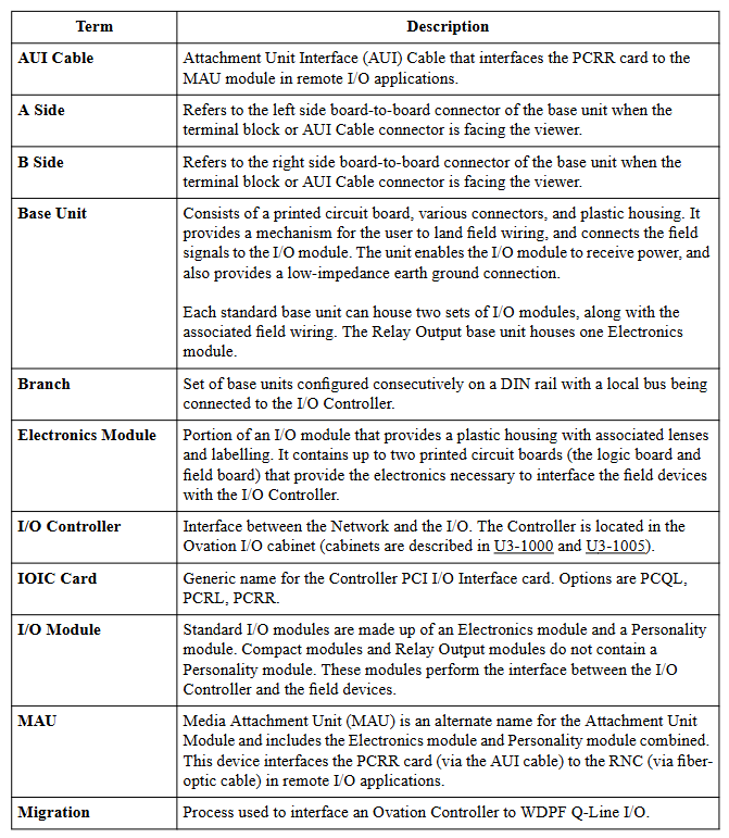
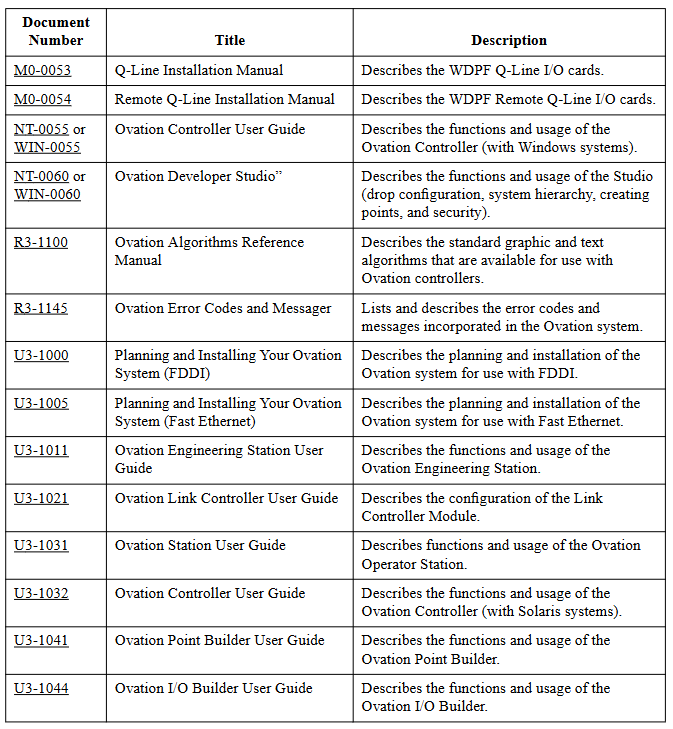
The Ovation I/O Reference Manual (R3-1150 Rev 3) is a reference manual written by Emerson Process Management for the input/output (I/O) modules of Ovation distributed control systems. This manual provides detailed information on the characteristics, specifications, installation, configuration, wiring, and diagnosis of various I/O modules, aiming to provide users with comprehensive guidance on the use of I/O modules, suitable for industrial control fields such as power generation and water supply and drainage.
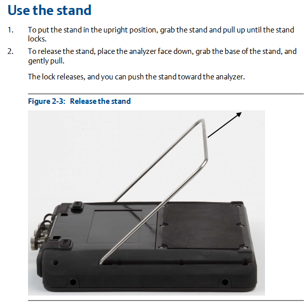
Main content
Noise suppression technology (Section 2)
Analyzed the causes and suppression techniques of electrical noise, including background knowledge of noise, identification methods (based on energy level, frequency, source), noise sources (inductive devices, AC/DC power circuits, etc.), noise classification (high, medium, low, extremely low), noise suppression methods (filtering, isolation, etc. of digital and analog signals), as well as analog signal shielding techniques and common input considerations.
Overview of I/O Modules (Section 3)
Outlined the features of Ovation I/O modules, such as support for local and remote configuration, modular design, DIN rail installation, etc; Introduced the composition of the module (standard module includes electronic module, personality module, and base unit, relay output module includes electronic module and base unit); It also covers the installation, configuration and status of modules, diagnostic LEDs, user replaceable fuses, and personalized module jumpers, and provides environmental specifications for I/O modules.
Detailed Introduction to Various I/O Modules (Sections 4-25)
Detailed explanations were provided for 13 bit analog input module, 14 bit analog input module, high-speed analog input module, analog output module, contact input module, compact contact input module, digital input module, compact digital input module, digital output module, HART analog input module, HART analog output module, link controller (LC) module, loop interface module, pulse accumulator module, etc., including module description, group division, external power supply, technical specifications, terminal block wiring information, on-site connection wiring diagram, address location, and diagnostic LED.
Ovation Local I/O and Remote I/O (Sections 26-27)
Introduced the overview, characteristics, components, cable requirements, configuration, and diagnostic LED of local I/O and remote I/O.
Appendices A-D
Contains supplementary information such as Q-Line card type, Ovation electronic ID, CE mark specifications, and instructions for using external power supply.
Summary of Changes
This revised version has added CE marking information for most chapters, added multiple personalized module fuses in Table 3-3, added relevant chapters and tables for high-speed analog input module, 16 bit HART analog input module, and 14 bit HART analog output module, replaced module group numbers in Table 27-1, added module group numbers for remote node controller module, replaced Appendix C, added warning information to the wiring diagram of the 14 bit analog input module, added part numbers to the warning information of the relay output module, corrected the part numbers of the relay output base component, added a reference to U3-1005 at the mention of U3-1000, defined a new firmware level for valve positioner (RVP), used graphics for RVP calibration, Added configuration commands kServo and kServoDB The troubleshooting content for the valve positioner and MAU subsystem has been added with an optical guide, and all chapters have miscellaneous clarifications and/or corrections.
Core Features
Modularity and compatibility: The I/O module adopts a modular design, which is easy to install, configure, and replace, and is compatible with previous models. It provides migration programs to update the control logic and database of old models.
Reliability and safety: The modules have good isolation performance, fault diagnosis capability, and redundancy design (some modules), which comply with relevant standards (such as IEC 61131-3). Some modules have obtained Achilles Level 1 certification to ensure stable and reliable operation of the system.
Wide applicability: Supports multiple signal types (analog, digital, pulse, etc.) and communication protocols (such as HART) to meet the control needs of different industrial scenarios.
Detailed technical specifications: Each module provides precise technical parameters such as input/output range, resolution, accuracy, sampling rate, isolation voltage, working environment conditions, etc., providing accurate basis for user selection and use.
The HART (Highway Addressable Remote Transformer) high-performance analog input module is a standard Ovation I/O module, updated to the 3rd edition of the Ovation I/O Reference Manual on March 3, 2003, and should be placed between Chapters 14 and 15. It provides 8 globally isolated 4-20mA analog inputs, equipped with HART transceivers, each of which is connected to a dedicated UART through optical isolation communication to maximize HART communication. This module can communicate with HART devices and support “smart” field devices. The analog 4-20mA signal, digital communication, and sometimes power supply of such devices can coexist on the same pair of wires.
Module group
Electronic module: There is only one set of 5X00106G01, which can connect 8 current loop signals with an input range of 4-20mA.
Personality module: There is only one set of 5X00109G01, which includes a printed circuit board component with 8 fuse inputs and user accessible jumper wires. It can be configured with transmitters for on-site or local power supply channels one by one.
Power supply
The logic circuit is powered by a standard+24V Ovation main power supply.
The on-site power supply is provided by a 24V auxiliary power supply, including all 4-20mA loop power supplies, A/D converters, and other output channel components. It can be a standard 24V Ovation auxiliary power supply or an external power supply provided by the user.
It is recommended to use the Ovation cabinet’s auxiliary+24V DC power supply. If an external auxiliary power supply is used, its noise should be ≤ 1.2Vrms.
All modules using auxiliary power sources (including HART modules) must use shielded I/O cables to suppress coupling noise and transients.
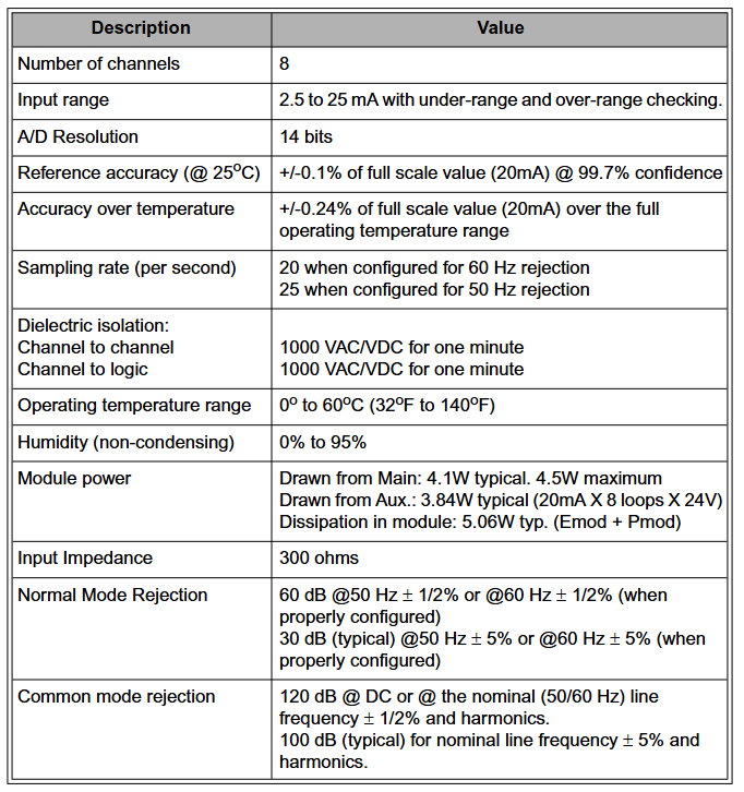
Technical specifications
Number of channels: 8
Input range: 2.5 to 25mA, with under range and over range checks
Full operating temperature range accuracy: ± 0.24% full-scale value (20mA)
Sampling rate (per second): 20 times when configured for 60Hz suppression; 25 times when configured for 50Hz suppression
Dielectric isolation between channels: 1000VAC/VDC, lasting for 1 minute; Channel and logic: 1000VAC/VDC, lasting for 1 minute
Working temperature range: 0 ° C to 60 ° C (32 ° F to 140 ° F)
Humidity (non condensing): 0% to 95%
Module power consumption: main power supply: typical 4.1W, maximum 4.5W; auxiliary power supply: typical 3.84W (20mA x 8 loops x 24V); Module Dissection: Typical 5.06W (Emod+Pmod)
Input impedance: 300 ohms
Common mode rejection ratio: 120dB for DC or nominal (50/60Hz) line frequency ± 1/2% and harmonics; typical 100dB for nominal line frequency ± 5% and harmonics
Personalized module and wiring information
Personality module: Each channel has a 1/20A fuse for loop protection, and each channel has a pair of user accessible jumpers that can be configured as locally or on-site powered transmitters according to the channel. The fuses and jumpers can be accessed from the top of the module.
Wiring information: There is a simplified wiring diagram label on the side of the personality module, indicating the connection method between the on-site wiring and the base unit terminal block. Each channel has two wiring configurations (depending on the transmitter configuration for local or on-site power supply), and relevant abbreviations are defined.
Register Mapping and Function
The module has 16 direct registers, including indirect memory indexes, analog input channel data, calibration registers, channel error bits, module configuration/status registers, HART enable registers, etc. Among them, module status register # 13 (hexadecimal D) can be read through the operator station’s point information window, and word address # 12 (hexadecimal C) is used to report errors in 8 input channels.
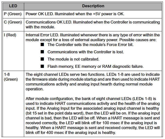
Diagnostic LED
P (green): LED with normal power supply, lights up when the+5V power supply is normal.
C (green): Communication is normal LED, which lights up when the controller communicates with the module.
I (red): Internal error LED, which lights up when any error occurs inside the module (except for loss of external auxiliary power supply). Possible reasons include forced error bits in the controller setting module, loss of communication with the controller, etc.
1-8 (green): Eight channel LEDs indicate firmware status during module startup and HART communication activity and analog input health during normal operation.
Other
The requirements for on-site wiring cables can refer to the HART FSK physical layer specification (HFC_SPEC-54).
The point data register is located at positions 2-9, corresponding to analog input points 1-8 respectively.
The HAI, HAO, and IAH modules are capable of retrieving additional variables from field devices, known as “multivariate”, including PV (primary variable), SV (secondary variable), TV (tertiary variable), and QV (quarterly variable).
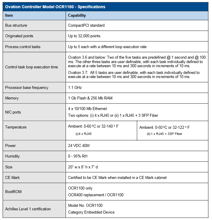
Ovation ™ The Controller Model OCR1100 is a controller in Emerson’s Ovation distributed control system, known for its precise control and excellent performance, suitable for critical task operations such as power generation and water supply and drainage. It can execute simple or complex adjustment and sequential control strategies, complete data acquisition functions, and interface with Ovation network and various I/O subsystems, generating up to 32000 points.
Main characteristics
Reliability and safety: It has the ability to control critical tasks safely and reliably, and can achieve disturbance free automatic fault transfer between redundant controllers; Obtained Achilles Level 1 certification, compliant with IEC 61131-3 standard.
Efficiency: Using Intel processors, it can simultaneously execute up to 5 process control tasks with a wide range of loop speeds (10 milliseconds to 300 seconds), and different software versions have different settings for task loop speeds.
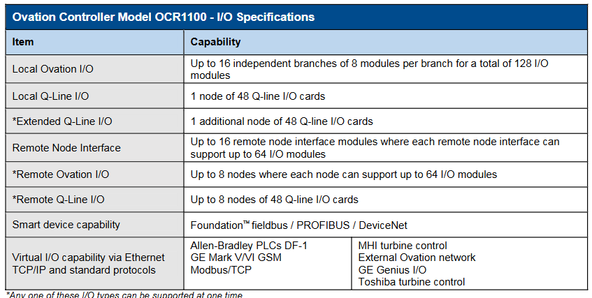
Interface and compatibility: Can interface with local and remote Ovation and WDPF I/O interfaces; Integrate interface with digital bus through Ovation I/O module; Capable of integrating virtual I/O and connecting to third-party OEM systems via Ethernet protocol; Supports multiple smart device protocols, such as Foundation ™ Fieldbus, PROFIBUS, DeviceNet, etc.
Storage and functionality: non-volatile storage applications, point databases, configuration information, and operational adjustment constants; The event sequence function with a resolution of 1 millisecond can record the sequence of digital input state changes and can also be used for control schemes; Sensors/limit checks, alarm processing, engineering unit conversion, database storage, etc. that can handle process points.
Structural features: small size, low power consumption, fanless operation; Adopting an open architecture based on CompactPCI ® Bus design and real-time operating system facilitate the integration of new technologies and protect software investments; The hardware is based on industry standards and uses Intel processors and CompactPCI bus technology, making it easy to upgrade and port.
Controller type
Simulator controller: using simulated I/O instead of actual hardware I/O system, integrating control scheme with process model or simulation interface, can be used for factory acceptance testing, etc.
Advanced controller: executes authorization algorithms with advanced functions, such as autoregression, dynamic matrix, fuzzy logic, etc.
Virtual Controller: Reproduces Ovation hardware controllers using real-time operating systems on Windows based platforms, mainly used for Ovation simulation solutions, without hardware I/O support.
Redundant functions
Redundant configuration: Key components (such as network interfaces, processors, power supplies, etc.) have multi-level redundancy, and the standard hardware configuration is a passive backplane, with a main controller and a backup controller installed.
Working mode: The main controller directly accesses I/O in control mode, performs data acquisition and control functions, and monitors the backup controller; The backup controller performs diagnostics in backup mode, monitors the main controller, and keeps data updated by polling the main controller database.
Automatic fault transfer: When the main controller fails, the backup controller immediately executes the control application program to achieve disturbance free switching. Multiple events can trigger fault transfer, and the fault processor can restore the backup role after repair.
Technical specifications
Basic parameters: The bus structure is based on the CompactPCI standard; Processor reference frequency 1.1 GHz; 1 GB of flash memory and 256 Mb of RAM; Four 10/100 Mb Ethernet NIC ports with two options; The working environment temperature and humidity have corresponding ranges; The size is 20 “w x 8” h x 7 “d; The power supply is 24 VDC 40W.
I/O capability: Supports multiple I/O systems, with up to 16 independent branches for local Ovation I/O, totaling 128 modules; 48 cards per local Q-Line I/O node, and expanding Q-Line I/O can add 1 node; Remote node interfaces also have corresponding support capabilities; Capable of virtual I/O through Ethernet TCP/IP and standard protocols.
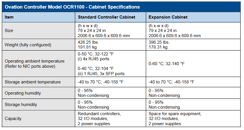
Cabinet specifications: The standard controller cabinet and expansion cabinet have the same size (79x24x24 inches), but there are differences in weight, capacity, etc; There are also regulations on the temperature and humidity range for work and storage.
Other information
The controller and I/O modules are both installed on DIN rails, and the cabinet configuration is flexible with multiple options. Customized cabinets can also be provided.
The hardware platform is constantly evolving and compatible with previous models, providing migration programs to update old model control logic and databases.
Copyright belongs to Emerson from 2017 to 2019. Product information is for reference only and sales are subject to relevant terms. The company reserves the right to modify product design or specifications.
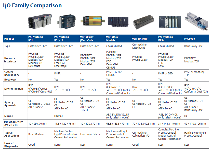
PAC8000 Remote I/O is a fully modular I/O solution suitable for general and hazardous area applications. Based on the carrier system, it supports multiple modules and I/O functions, including intrinsic safety signals. Its open architecture can communicate with various different fieldbuses by selecting appropriate types of bus interface modules (BIM). This product is designed to withstand extreme temperatures, humidity, corrosive substances, impacts, and vibrations, providing full specification performance even in the harshest environments and performing well in ATEX environments. All components can be installed and operated live in Zone 2/Division 2 and ATEX Zone 1 hazardous areas, and I/O includes types that can be directly connected to intrinsic safety (Exi) or increased safety (Exe) field wiring, seamlessly integrated with PACSystems solutions, and connected to RX3i and RSTi EP controllers via PROFINET or Modbus TCP.
Main characteristics
Operation in harsh and hazardous areas: It can operate within the range of -40 ° C to+70 ° C, withstand ISA Level G3 corrosion, 30g impact, and 5g vibration, and is suitable for Class I, Division 2, and Zone 2 hazardous areas. Its I/O module field wiring includes intrinsic safety (Exi) and increased safety (Exe) options, and also supports UL HAZLOC C1D1 and ATEX Zone 1 hazardous areas.
High availability: Supports PROFINET system redundancy (PNSR), enabling synchronized independent controllers to serve I/O and seamlessly transition from active controllers to backup controllers. Controllers can be up to 10 kilometers apart and can handle physical interrupts.
Rich I/O modules: In addition to analog and digital I/O, there are multiple modules to choose from, including options for low-level instruments, AC power supply, and intrinsic safety signals. There are 4, 8, 16, and 32 channel modules, and all modules provide comprehensive diagnostic information.
Easy troubleshooting and machine setup: PAC8000 I/O can be easily configured using the integrated PAC Machine Edition (PME) software. If PROFINET is used, configuring through GSDML files is even simpler. PME software is compatible with all PACSystems CPUs, requiring only one tool for small to large applications and simplifying HMI development.
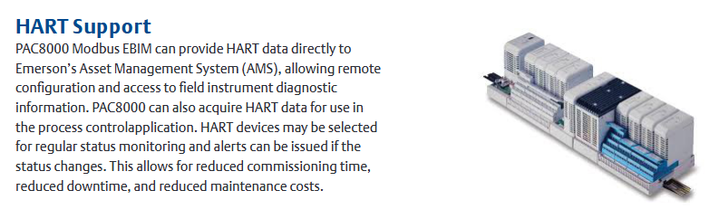
HART support: PAC8000 Modbus EBIM can directly provide HART data to Emerson’s Asset Management System (AMS), allowing remote configuration and access to on-site instrument diagnostic information. It can also obtain HART data for process control applications. HART devices can be selected for routine status monitoring, and alarms can be issued when the status changes, reducing debugging time, downtime, and maintenance costs.
Specification parameters
Installation format: DIN rail.
Network interfaces: PROFINET, Modbus/TCP.
Gateway/Bridge: HART.
Network redundancy: MRP, dual LAN.
System redundancy: PNSR or Modbus/TCP.
I/O redundancy: Dual redundancy.
Media support: Copper cables and multimode optical fibers.
Isolation: Galvanic isolation, DI, DO, AI, AO are all isolated.
Hot swappable: supported.
Environmental parameters: IP20 protection level, operating temperature from -40 ° C to 70 ° C, with normal coating, resistant to ISA Level G3 corrosion, able to withstand 30g impact and 5g vibration.
Institutional certification: UL, UL HAZLOC C1D1, CE, ATEX Zone 1, intrinsic safety certification, as well as classification society certification (such as Lloyd’s Register).
The A6500-LC linear adjustable displacement sensor (LVDT) preamplifier is a single channel device used to connect half bridge inductive sensors or LVDT sensors with CSI 6500ATG. It provides excitation voltage for the sensor and proportionally converts the displacement signal measured by the sensor into an output voltage range suitable for the A6500UM universal measurement card.
Main parameters
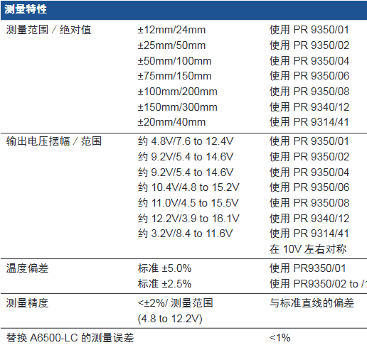
Measurement characteristics
Measurement range/absolute value: There are multiple ranges when used with different types of sensors, such as ± 12mm/24mm when using PR 9350/01, ± 25mm/50mm when using PR 9350/02, etc.
Output voltage swing/range: varies depending on the sensor model, for example, about 4.8V/7.6 to 12.4V when using PR 9350/01, about 9.2V/5.4 to 14.6V when using PR 9350/04, etc., and is symmetrical around 10V.
Temperature deviation: When using PR9350/01, the standard is ± 5.0%, and when using PR9350/02 to/12, the standard is ± 2.5%.
Measurement accuracy: Deviation from standard straight line<± 2%/measurement range (4.8 to 12.2V).
Replace the measurement error of A6500-LC:<1%.
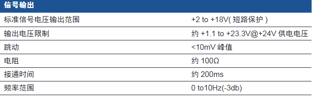
Signal output: The standard signal voltage output range is+2 to+18V (short circuit protection); The output voltage limit is approximately+1.1 to+23.3V @+24V supply voltage; Jumping<10mV peak value; The resistance is about 100 Ω; The connection time is about 200ms; the frequency range is 0 to 10Hz (-3db).
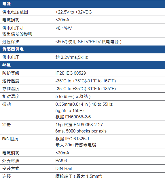
Power supply
Power supply voltage range:+22.5V to+32VDC.
Current loss:<30mA.
The influence of power supply voltage on output signal:<0.1%/V.
Overvoltage protection:<60V (using SELV/PELV power supply).
Sensor supply voltage: approximately 2.2Vrms, 5kHz.
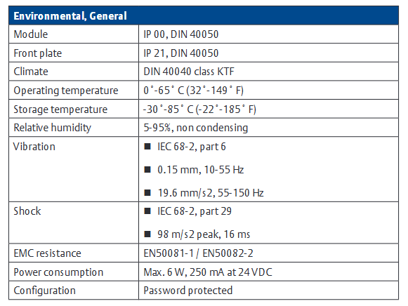
Environmental parameters
Protection level: IP20 IEC 60529.
Operating temperature: -35 ° C to+75 ° C (-31 ° F to 167 ° F).
Storage temperature: -35 ° C to+85 ° C (-31 ° F to 185 ° F).
Relative humidity: 5 to 95% (no condensation).
Vibration: 0.35mm (0.014 in), 10 to 55Hz; 5g,55 to 150Hz, According to EN60068-2-6.
Impact: 15g according to EN 60068-2-27, 6ms, 5000 impacts per axis.
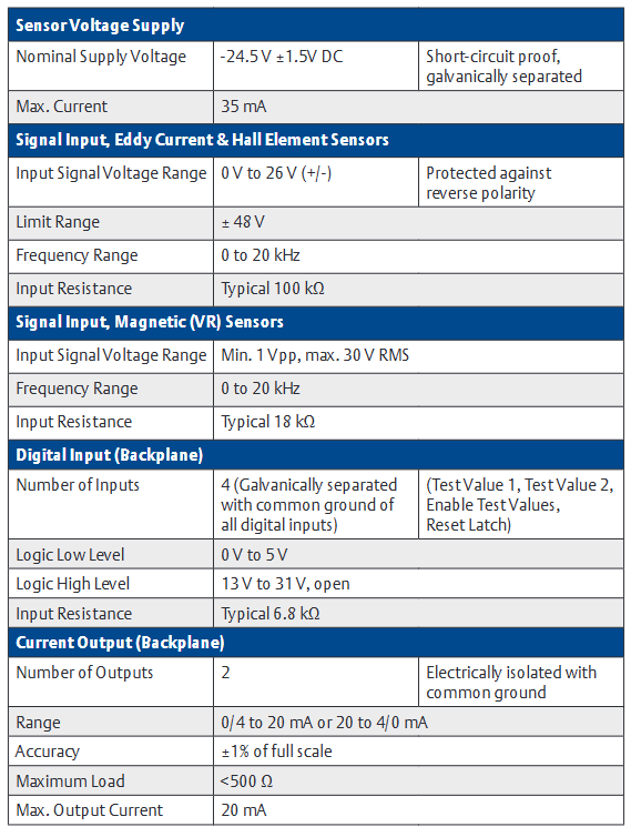
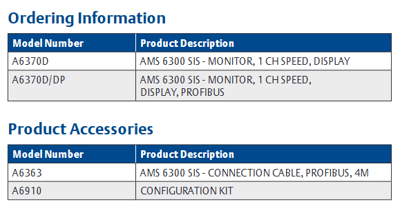
The A6370 monitor is part of the AMS 6300 SIS overspeed protection system and is installed in a 19 inch rack (84HP width and 3RU height) in combination with the A6371 system backplane. A set of AMS 6300 SIS consists of three protection monitors (A6370) and one backplate (A6371), suitable for eddy current sensors, Hall element sensors, and magnetic (VR) sensors.
Main parameters
Sensor voltage supply
Nominal supply voltage: -24.5 V ± 1.5V DC, with short-circuit protection and electrical isolation.
Maximum current: 35 mA.
Signal input
Eddy current and Hall element sensors: Input signal voltage range of 0 V to 26 V (±), with reverse polarity protection, limited range of ± 48 V, frequency range of 0 to 20 kHz, typical input resistance value of 100 k Ω.
Magnetic (VR) sensor: Input signal voltage range minimum 1 Vpp, maximum 30 V RMS, frequency range 0 to 20 kHz, typical input resistance value 18 k Ω.
Digital input (backplane)
Input quantity: 4 (electrically isolated, all digital inputs are grounded), including test value 1, test value 2, enable test value, reset latch.
Logic low level: 0 V to 5 V; Logic high level: 13 V to 31 V (open circuit).
Output quantity: 7 (short circuit protection), including outputs 1 to 6, channel normal (COK).
Logic low level:<100 mV; Logic high level: -2 V (system supply voltage).
Maximum current: 25 mA.
Pulse output
Backboard: 3, open collector emitter, current limiting, electrical isolation; Maximum voltage 31.2 V; maximum current 16 mA at 24 V; frequency range 0 to 20 kHz.
Front panel: 1 (short circuit protection); Voltage ranging from 0 to 5 V (TTL signal); Frequency range 0 to 20 kHz; The typical output impedance is 10 k Ω.
Sensor output (front panel)
Output quantity: 1 (short circuit protection).
Voltage: 0 to 3.9 V, coefficient 0.15 ± 3%.
Frequency range: 0 to 20 kHz.
Typical output impedance value: 10 k Ω.
Communication
USB: Configuration interface, USB B-type.
RS 485: Up to 32 devices with baud rates of 38400, 57600, and 115200 baud.
Profibus DP (A6370D/DP only): up to 31 devices, with a data transmission rate of up to 12 Mbit/s.
Reaction time
Speed:<measurement time+8 ms.
The typical reaction time at 3000 min ⁻¹ is 35 ms in the “once per revolution” mode and 12.5 ms in the “automatic” mode.
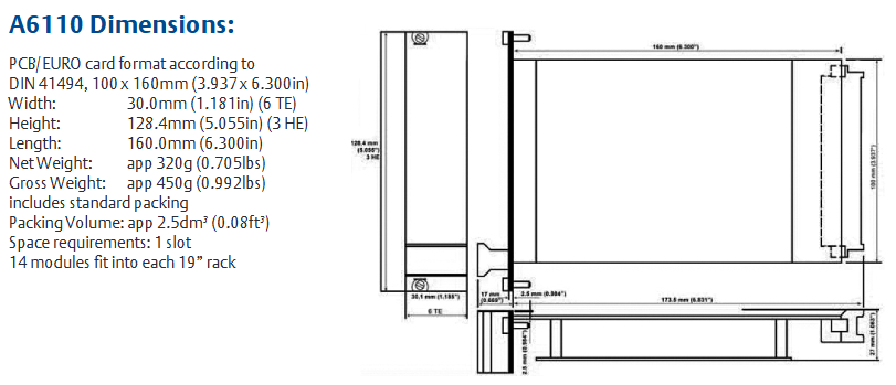
The A6110 axis relative vibration monitor is designed specifically for the most critical rotating machinery in factories and has extremely high reliability. As a 1-slot monitor, it can be used in conjunction with other AMS 6500 monitors to build a complete API 670 mechanical protection monitoring system, suitable for applications such as steam, gas, compressor, and hydro turbine machinery. Its main function is to accurately monitor the relative vibration of the shaft, and drive the alarm and relay by comparing the vibration parameters with the alarm settings, thereby reliably protecting the machinery.
The relative vibration monitoring of the shaft is achieved through displacement sensors, which can be installed inside the bearing box or bearing seat, targeting the rotating shaft. Due to the installation of displacement sensors on bearings, the monitored parameter is the relative vibration of the shaft, that is, the vibration of the shaft relative to the bearing housing. On all sliding bearing machines, shaft relative vibration is an important measurement parameter for prediction and protection monitoring, suitable for situations where the machine housing has a relatively large mass relative to the rotor, and the bearing housing is expected to not vibrate within the machine speed range from zero speed to production state.
AMS 6500 is PlantWeb ® Components of AMS software. PlantWeb will collaborate with Ovation ® And DeltaV ™ The operation integration of process control system and mechanical health status is provided to users; AMS software provides maintenance personnel with advanced predictive and performance diagnostic tools, helping to accurately diagnose machine failures as early as possible.
Main parameters
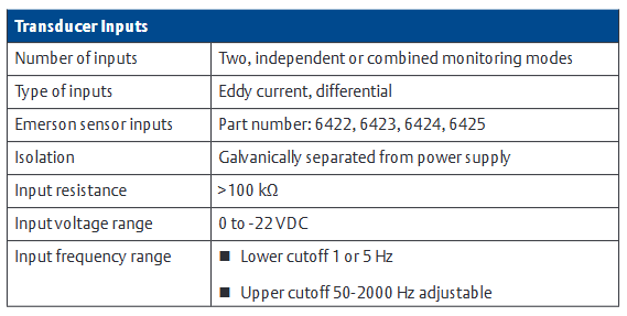
Sensor Input
Input quantity: 2, supporting independent or combined monitoring modes.
Isolation: Galvanically separate from the power supply.
Input resistance:>100 k Ω.
Input voltage range: 0 to -22 VDC.
Input frequency range: lower limit cutoff 1 or 5 Hz, upper limit cutoff 50-2000 Hz (adjustable).
Measurement range
Scope: It can be continuously adjusted through configuration software.
Minimum range: 0-400 mV.
Maximum range: 0-8000 mV.
Sensor power supply: An independent buffer sensor power supply that is diagonally separated from all system voltages and system supply voltages, with open and short circuit protection.
Nominal voltage: -26.7V.
Available current: nominal 20 mA, maximum 35 mA.
Front panel output
Two green LEDs indicate that each channel is functioning properly.
Two red LEDs indicate the alarm and danger status of each channel.
Front panel buffer output: 2, same as sensor input, ± 10 V, load>100 k Ω, frequency range 0.1-5 kHz (-3 dB), 0-16 kHz -3 dB ± 20%.
Mini DIN configuration socket: used for module interface connection for configuration, parameter and status monitoring, RS – 232。
Handle: A panel that facilitates card removal and provides module and sensor recognition.
analysis function
Measurement mode: Hot configurable, including multiple modes such as zero to peak, peak to peak, independent dual channel, or combined dual channel modes.
Analysis parameters: 1/2x, 1 to 10x, and the same phase angle, which can be obtained through ModBus TCP/IP output.
Rear output
Current mode output: Each channel outputs 0/4-20 mA, proportional to the main value, allowing a load of<500 Ω, with an accuracy of ± 1% of full scale, and a stabilization time of 0 to 10 seconds (configurable).
Voltage mode output: Each channel outputs 0-10 VDC, proportional to the main value, with open/short circuit protection, allowing loads greater than 10 k Ω.
Rear buffer output: The original buffer output signal (AC and DC) has open/short circuit protection, with a frequency range of 0.1-16 kHz (-3 dB), 0-16 kHz -3 dB ± 20%, and allows for a load greater than 10 k Ω.
DC voltage output: 0-10 VDC output, proportional to the shaft position (gap), with open/short circuit protection, accuracy of ± 1% of the range, allowing load>10 k Ω.
This document is from FloBoss ™ The user manual for S600+Flow Computer covers various aspects such as security precautions, installation, hardware modules, operation, startup, and troubleshooting, aiming to guide users in correctly installing, configuring, operating, and maintaining the device.
Safety precautions
Pre operation reading: Before operating the equipment, it is necessary to carefully read the manual to understand the safety implications. Improper use may result in damage or injury, and the manual should be placed in a convenient location for reference.
Process protection: Equipment failure may cause the operation process to lose appropriate protection, and additional backup equipment or alternative protection measures need to be considered.
Equipment return: When returning the equipment, it is necessary to ensure that it is cleaned to a safe level that complies with relevant laws and regulations, and to bear the responsibility for any non-compliance.
Grounding requirements: The exposed metal parts of metal casings and electrical instruments must be grounded in accordance with OSHA rules and regulations, and mechanical or pneumatic instruments containing electrical operating equipment must also be grounded.
Electrostatic protection: The equipment contains sensitive electronic components that are susceptible to damage from electrostatic discharge and require proper maintenance and handling.
System training: Trained employees are crucial for successful operations and can receive training in various ways.
Ethernet connection: This automation device is suitable for Ethernet networks without public access, and it is not recommended to connect to public Ethernet networks.
Installation
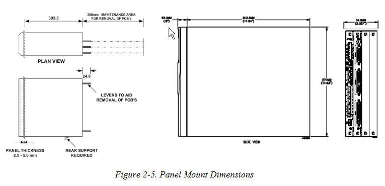
Installation preparation: The installation must comply with local regulations and laws, follow good manufacturing practices, and understand the modular design and main components of the equipment.
Environmental considerations: The device is panel mounted and should be placed in a convenient, comfortable, and safe location. Attention should be paid to the heat dissipation of multiple devices in small spaces.
Required tools: including suitable screwdrivers, wrenches, Allen keys, etc.
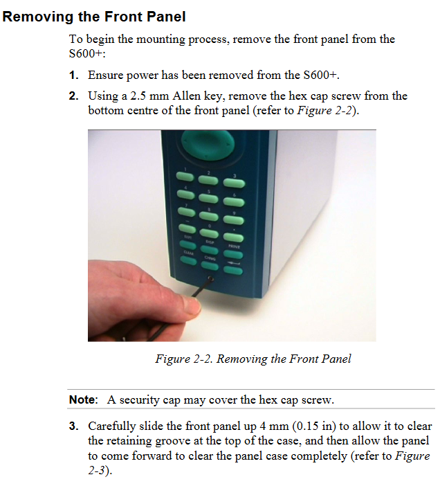
Installation steps: including unpacking inspection, dismantling the front panel, installing the panel installation unit, reinstalling the front panel, etc.
Module installation and disassembly: Follow the correct steps, pay attention to electrostatic protection and power-off operation.
EMC protection installation: Install electromagnetic compatibility protection components according to on-site requirements, such as safety backplates, filter adapters, ferrite fixtures, etc.
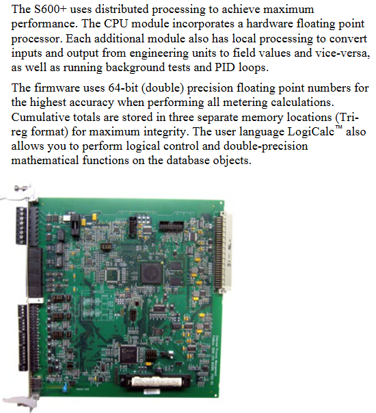
CPU module
Module Introduction: Includes host processor and related peripherals, with multiple connection interfaces on the back. Pay attention to wiring specifications and avoid improper use of instruments for testing.
Power supply: The power connection is a plug-in standard terminal block with input and output voltage specifications, built-in anti surge fuse, and provides stable output voltage.
**Watchdog relay * *: Single pole double throw relay, energized during normal operation, de energized in case of CPU failure.
Onboard battery backup: used to preserve SRAM, CMOS memory area, and calendar clock content, replaceable, with corresponding steps and precautions for replacement.
Communication ports: including RS-232 serial port, RS-422/RS-485 multi drop port, Ethernet LAN port, local operator PC or remote display port, etc. Each port has its own pin definition and connection requirements.
Connectors and jumpers: There are multiple types of connectors and jumpers used for different functional settings. The default configuration is specified, and it is not recommended to modify them without professional guidance.
USB port: Used to export alarm history, event history, and report history information to a USB flash drive.
Input/Output (I/O)
I/O module (P144): It can measure process signals and provide multiple input/output types, such as analog input, analog output, digital input, digital output, etc. Each type has its own pin definition, wiring method, and functional characteristics.
Prover module (P154): designed specifically for various provers, with specific input-output configurations and functions.
HART module (P188): Provides communication between HART devices and S600+, with corresponding connection and wiring methods.
Mezzanine module (P148): Provides pulse input, installed on I/O and prover modules, affecting specific pulse channels.
Front panel
Description: Provides a local interface to view or modify system parameter values and status, including front panel ports, keyboards, LCD displays, etc.
Front panel port: located at the bottom of the front panel, it is the main connection port for transferring configuration files in the Config 600 software, with specific pin definitions.
Keyboard: includes function keys, directional and menu keys, numeric keys, operation keys, alarm LEDs, and alarm keys, each with its own function.
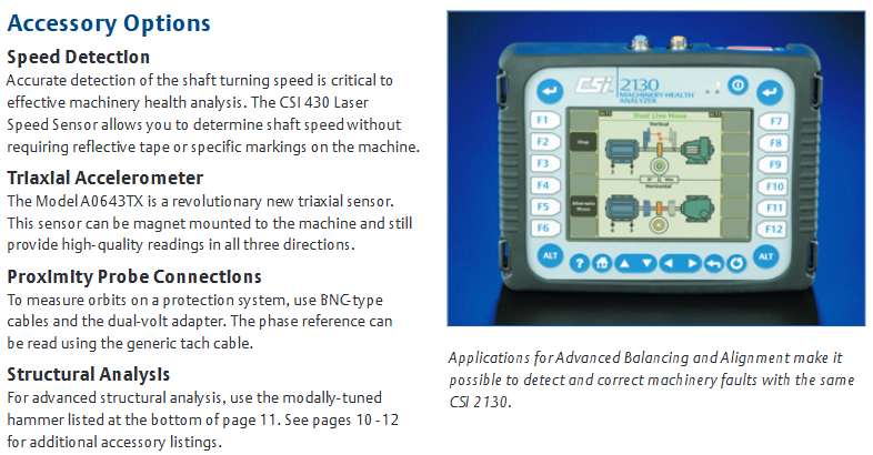
The CSI 2130 Machinery Health Analyzer is a device that integrates data collection, vibration analysis, alignment, and balancing functions, designed specifically to meet the efficient work needs of maintenance departments with reduced personnel and budget. It is easy to operate, can quickly and accurately identify potential equipment failures and identify the root cause, and can also upload data to AMS Suite to provide a unified view of the health status of factory equipment, helping to improve factory availability and reliability.
Core advantages
Efficient data collection: Compared with the previous generation product CSI 2120, the data collection time is reduced by up to 60%. The dual channel option can additionally reduce measurement time by 20% -45% through patented data collection technology, enabling monitoring of more machines and improving work efficiency.
Portable and durable
Equipped with a large color backlit VGA display screen, suitable for various environments.
Small in size and lightweight (4.5 lbs), making it easy to carry over long distances.
Featuring IP 65 protection level and optional security certification, suitable for use in industrial environments.
Easy to operate: With minimal training, it can effectively operate and convert data into actionable equipment health information, such as automatically distinguishing between unbalance and bearing faults, allowing users to immediately focus on critical machine issues.
Embedded intelligence: Even novice users can perform complex diagnostic tests through simple operations, fully utilizing the device’s role on site.
Key functions
Fault detection capability
Using patented PeakVue ® Processing technology can detect stress waves, detect signs of bearing and gear wear at the earliest, provide indications of fault severity, and convert them into reliable trends to determine the optimal maintenance time.
With an excellent frequency range, the patented low-speed technology (SST) can accurately measure low-speed equipment signals, up to 80000 Hz, suitable for high-speed mechanical diagnosis.
On site analysis tools: including waveform autocorrelation, fault frequency superposition, narrowband parameter trend analysis, 14 predefined analysis experts, four quadrant plotting, etc., to assist in in-depth analysis of equipment problems.
Variable speed analysis: During the routine data collection process, all diagnostic tools can be automatically adjusted to adapt to changes in equipment speed and accurately assess potential issues on site.
Predicting catastrophic failures: By collecting signals from online monitoring systems, generating track maps to identify issues such as misalignment and shaft friction, trend data can help detect structural failures.
Monitoring fault points: With the help of line power supply, it can be used as a temporary online monitor to monitor the health status of equipment for a long time, automatically obtaining and storing data.
Capture machine shutdown status: For transient event analysis, a series of vibration snapshots can be collected during equipment startup, shutdown, or process changes, which can be viewed separately or in a waterfall chart.
Linking vibration and process variables: Using dual channel functionality, process information is input as a voltage signal into one channel, while vibration is monitored in the other channel to identify machine problems.
Multi functional configuration
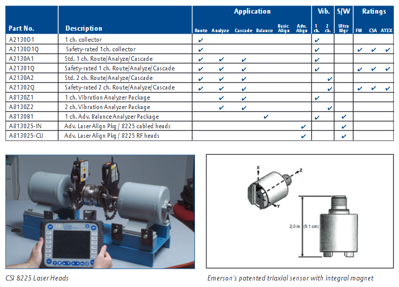
Modular design: It can be configured according to current requirements, and can easily expand functions as requirements change, protecting initial investment. It can be used as a single channel or dual channel analyzer, dedicated field balancer, or laser alignment calculator, and can also add modules for transient and structural analysis.
Advanced cross channel analysis: Standard data collection is a good foundation for identifying equipment failures, and cross channel analysis helps identify the root cause of the failure. Dual channel devices can display tracks, optional advanced cross channel applications can expand functionality, ODS/modal applications make structural analysis simpler, and cross channel data can be analyzed or exported in relevant software.
Advanced transient analysis: expands the functionality of single channel or dual channel devices, allowing for long-term recording of raw vibration signals for post-processing and analysis. It is suitable for diagnosis of turbomachinery, start-up and shutdown, or machines with short repetitive work cycles. The data can be checked on the device or in related software.
On site balancing: Advanced balancing applications make devices powerful on-site balancers, with a graphical user interface guiding operations, basic and advanced modes, special features such as vector averaging and balance monitoring, and the ability to print or store job documents.
Laser alignment: Advanced laser alignment applications provide a graphical driven user interface and wireless operation, with built-in dual inclinometers to automatically determine axis position, real-time movement options, and job documentation available in relevant software.
Motor current analysis: with MotorView in AMS Machinery Manager ® Module coordination, using standard current clamps or patented magnetic flux monitoring, for non-invasive analysis of the rotor and stator condition of induction motors.
Specification parameters
Physical data: The color display screen is a 5.75 “x 4.25” transflexible LCD screen with backlight and a resolution of 640 x 480 pixels; The keyboard has large easy to press keys, 12 soft function keys, and context sensitive help keys; The dimensions are 8 “high x 1.88” deep x 10.25 “wide; Weight 4.5 lbs.
Operating conditions: Sealed casing, IP-65 protection level; The working temperature ranges from 15 to 113 º F (-10 to 50 ° C).
Power supply: Nickel hydrogen battery, 4.5 ampere hours, 7.2 V; typically used for 8 hours (longer when backlight is turned off), data can be saved when battery voltage is low; Equipped with an “intelligent charger” that can discharge, quickly charge, trickle charge, and also serve as a continuous power source; Charging time is 3 hours.
Quality assurance: NIST traceable calibration; There is a safety rating version approved for use in Class I, Zone II, Groups A, B, C, and D. The performance specifications of the safety rating version are the same as those of the standard model.
Safety certification: CSI 21302Q has obtained multiple safety certifications such as FM, CSA, ATEX, etc.
Analysis and routing specifications
Analysis experts: including various interactive data acquisition settings such as high-frequency, high-resolution, and bearing/gear fault analysis.
Data analysis speed: 400 lines/1000 Hz spectrum is 0.14 seconds/average; The 1600 line/1000 Hz spectrum is 0.5 seconds/average.
Analytical ability: noise floor PeakVue、 Demodulation SST、 There are corresponding performance indicators for dual channel, cross channel, and dynamic analysis; The signal range, frequency range, low-frequency response, resolution, average, average quantity, integration, triggering, anti aliasing and other parameters are also clearly defined.
Amplitude units: metric or imperial, acceleration, velocity, displacement, or user programmable.
Frequency units: Hz, CPM, Orders.
Scaling: Both the X and Y axes are linear or logarithmic.
Window: Hanning or Uniform.
Cursors: single cursor, harmonic cursor, moving harmonic cursor, edge band cursor.
Memory: 512 MB internal storage, equipped with a secure digital memory card slot, with almost unlimited memory.
Signal input: including power input, non power input, input impedance, tachometer, pseudotachometer, three-axis, output and other parameters.
Balance specifications
Basic mode: Provides pre configured tasks for balancing single and double planes, and a full calculator mode.
Advanced mode: up to 4 planes, up to 8 sensor inputs, up to 6 different speeds, automatic unit conversion, automatic weight distribution, trial weight estimation.
Special function: Vector averaging eliminates background vibration; The balance monitor automatically detects secondary mechanical faults; The graphical user interface provides data stability indicators, displays real-time imbalance vectors, and eliminates weight placement confusion.
Advanced mode: Quick specification alignment checker, manual scanning, two-way mode (uncoupled axis), vertical machine alignment, C-plane alignment, straightness measurement, enhanced soft foot detection, data averaging, custom machine configuration, custom tolerance values, additional real-time movement options, uploading jobs to software.
Communication: Standard measurement via cable, no cable measurement, optional RF (where allowed).
Special features: thermal growth compensation, real-time machine movement, Jackshaft application, recording annotations and observation results.
Accessories Options
Including speed detection (such as CSI 430 laser speed sensor), three-axis accelerometer, proximity probe connection, structural analysis tool, power supply, cable, housing, screen protector, various sensors, adapters, current clamps, battery packs and other accessories, can be selected according to needs.
This document is AMS 2140 Machinery Health ™ The user guide for Analyzer covers the basic introduction, operation methods, functional applications, data processing, and other aspects of this portable vibration analyzer. It is suitable for vibration analysts, reliability data collection technicians, and reliability engineers who monitor rotating machinery in process factory environments.
Introduction to analyzer
Basic equipment: including firmware media, Micro USB cable for connecting to AMS Machinery Manager, power supply for charging battery pack, screen protector, shoulder strap, etc.
Appearance and buttons
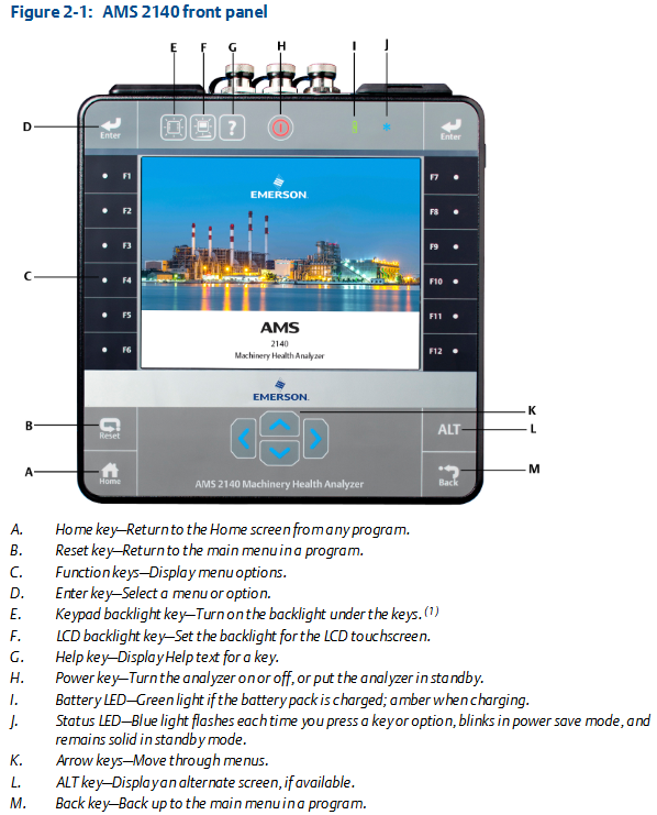
Front view: Includes Home key, Reset key, Function key, Enter key, Keyboard backlit key, LCD backlit key, Help key, Power key, Battery LED, Status LED, Arrow key, ALT key, Back key, etc. Each key has its specific function.
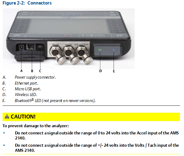
Top view: There are power connectors, Ethernet ports, Micro USB ports, wireless LEDs, Bluetooth LEDs (not available for newer models), etc.
First power on: The battery pack needs to be activated first, connect the provided power cord to the power outlet and analyzer, then press and hold the power button to turn on the device. After turning on, you can set the time and date.
battery pack
For rechargeable lithium-ion battery packs, they can usually be used continuously for more than 8 hours on a single charge, and a warning will be issued when the battery level is low.
The battery pack is in storage mode when it leaves the factory and needs to be activated according to the steps.
There are many usage and maintenance precautions, such as using only Emerson battery packs and chargers, environmental temperature limitations for charging and operation, temperature and power requirements during storage, etc.
External battery charger: It can charge the battery pack separately, with corresponding charging steps and precautions, such as ensuring good ventilation and temperature restrictions in the charging environment.
Power on and off: Press and hold the power button to operate, and you can also perform a hard restart and enter standby mode.
Main screen: Contains information such as time and date, Bluetooth connection status, battery level, supported channels, etc. There are two alternating screens displaying different programs and settings options.
Backlight: LCD backlight and keyboard backlight can be set, with different adjustment methods and energy-saving settings.
Touch screen: can be locked/unlocked, calibrated, supports gesture operation and on-screen keyboard input.
Menu navigation: Navigating through touch screen and function keys, with ALT screen for entering text and viewing help information.
Settings: Key buzzer, standby timer, backlight timer, print mode, low battery warning level, etc. can be set.
Memory card: It can be inserted into an SD memory card to store routing or job files, with steps and precautions for insertion and removal.
Bluetooth: If supported by the analyzer, it can be used to connect related devices and requires pairing, connection, and other operations, with different status icons.
Utility programs: including file utilities (for copying, deleting, and moving files), memory utilities (for viewing memory information, etc.), and battery utilities (for viewing battery status, etc.).
Cleaning the analyzer: Suitable cleaning products should be used in non hazardous areas to avoid the use of corrosive or abrasive substances.
Four channel input adapter: expandable analyzer function, with connection and usage methods.
Multiple inputs: The analyzer supports collecting data from multiple channels simultaneously, with connection options for different input quantities.
Dangerous place use: Different labeled analyzers have different applicable places, and there are specific precautions when using them.
Transfer files with AMS 2140
AMS Machinery Manager data transfer: can manage files in the analyzer, achieve routing and job transfer, storage, etc.
Independent data transfer application: suitable for computers without AMS Machinery Manager installed, capable of transferring files but with certain limitations.
Communication settings: including compatible AMS Machinery Manager versions, changing analyzer IDs, setting connection types (USB, Ethernet, wireless), etc.
Routing and Jobs: Routing and jobs can be loaded from AMS Machinery Manager, or transferred from the analyzer to AMS Machinery Manager or computer folders.
Analyzer firmware and programs: You can view version numbers, upgrade firmware, add or upgrade programs.
Screenshot: Screenshot can be taken and saved.
Start screen: The main screen image can be changed.
Printing: You can create a cover page and print charts to AMS Machinery Manager or a storage card.
Routing
Routing Overview: Routing is a list of devices and measurement points selected from a certain area of the AMS Machinery Manager database, which can be used to collect data and transmit it back to the database.
Manage routes: including viewing loaded routes, activating routes, deleting route data or routes, etc.
Set data collection and display parameters, such as setting plot type, enabling/disabling automatic advancement to the next measurement point, setting high-frequency detection average value, etc.
Tachometer: It can set tachometer parameters, save and call settings, etc.
Multiple inputs and measurements: Data can be quickly collected using multi-channel functionality and three-axis accelerometers.
Collecting routing data: Collect data step by step, including monitoring real-time vibration data, re measuring, skipping devices or points, etc.
Annotation: Annotations can be created, deleted, or added to routing measurement points.
Draw routing data: The collected data can be drawn and modified.
Run analysis to collect routing measurement point data: If abnormal data is found, the analysis program can be opened to further collect data.
View routing measurement point settings and history: You can view stored data, group status, trend history, etc.
Routing report: The routing report can be printed to AMS Machinery Manager or storage card.
Chart
View full screen chart: The chart can be displayed in full screen.
Select activity chart: Use the button to select the activity chart and operate it.
Switch chart type: Switch between different chart types based on the collected data type.
Add/Remove cursor: You can add and move a cursor to analyze data.
Change cursor type: There are multiple cursor types to choose from, suitable for different analysis needs.
Change the ratio of the x and y axes: You can set parameters such as the axis scale.
Expand or compress X-axis: You can zoom in or out of the X-axis to view data.
View the highest frequency peak on the spectrum: List the highest peak and view it.
Set RPM: Set RPM for routing points.
View the failure frequency on the chart: You can view the frequency related to equipment failures.
Analysis and Advanced Analysis
Analysis Overview: Can be used to collect data for troubleshooting, with different analysis experts and manual analysis modes.
Manage assignments: including creating, opening, editing, deleting assignments, etc.
Set display parameters, such as setting overlap rate and selecting the data type to be displayed when collecting spectra.
Multi input measurement: Multiple inputs can be used simultaneously to collect data, with corresponding setting methods.
Sensors and inputs: The number of inputs and sensor parameters can be set.
Tachometer: The setting method is similar to that in routing.
Common data collection parameters include Fmax and Fmin, resolution lines, window, average, PeakVue, demodulation, trigger, etc.
Collect data using analysis experts: Different analysis experts are suitable for different troubleshooting tests, with corresponding usage methods and recommended uses.
Collecting data through manual analysis: Different analysis modes can be set, such as waveform, spectrum, overall, etc., and relevant parameters can be set.
Monitor real-time vibration data in analysis: Monitor through Bluetooth devices, but do not store audio.
Re measure in analysis: data can be collected again.
Storing data to routing or analysis jobs: Data needs to be manually saved.
View previously collected data in the analysis: View temporarily stored data.
Print analysis charts to AMS Machinery Manager or storage card: Follow the corresponding steps.
Reset analysis default values: Reset the settings of the analysis program.
Advanced laser alignment
Overview of Basic and Advanced Laser Alignment Applications: Can be used for horizontal and vertical machine alignment and straightness measurement, with different modes and application scenarios.
Setting up lasers and sensors: including installing brackets, installing lasers and sensors, turning on equipment, adjusting laser beams, pairing sensors, etc.
Manage homework: can create, activate, copy, edit, delete homework, transfer homework, etc.
Set homework parameters, such as homework mode, alignment method, operation mode, etc.
Horizontal alignment: including steps such as inputting machine dimensions, obtaining alignment data, checking soft feet, viewing and adjusting machines.
Vertical alignment: Similar to horizontal alignment, there are corresponding steps and parameter settings.
Straightness measurement: including inputting contour dimensions, obtaining straightness data, viewing surface contours, etc.
Chart: You can view tolerance charts, etc., to analyze the alignment situation.
Transfer alignment tasks: can transfer tasks and tolerance tables, print summary reports.
Advanced Transient
Advanced Transient Overview: It can collect large and complete time waveforms for analyzing the behavior of equipment under changing conditions.
Manage assignments: including creating, activating, editing, deleting assignments, etc.
Sensors and inputs: Set the number of inputs and sensor parameters.
Tachometer: The setting method is similar to other modules.
Select a part of the complete transient waveform: set the number of displayed data points, lines, etc.
Set the number and type of charts to display in advanced transients: Select the type of chart to display.
Set data collection parameters such as Fmax, sampling rate, sample size, etc.
Collect transient data: Follow the steps to collect data, which can be remeasured or deleted.
Plotting data in advanced transients: displaying and analyzing collected data, printable charts.
ODS/Modal
ODS/Modal Overview: Cross channel ODS and modal data can be collected to determine the modal characteristics of elastic structures.
Manage assignments: including creating, activating, editing, deleting assignments, etc.
Sensors and inputs: Set the number of inputs and sensor parameters.
Tachometer: The setting method is similar to other modules.
Set Chart: Set the type and format of the displayed chart.
Set up homework: including setting measurement parameters, homework modes, collection parameters, etc.
Collect ODS/modal data: Collect data step by step, and perform related operations such as changing polarity, deleting data, etc.
Display data of ODS/modal measurement points: View collected data.
Print ODS/modal charts to AMS Machinery Manager or storage card: Follow the corresponding steps.