The MMS 677X series dual channel bar chart indicator (including MMS 6771 and MMS 6772) belongs to the MMS 6000 series machine monitoring system and is used to display the measurement results of the MMS 6000 module. With a dual channel design, the MMS 6000 monitor can display data from two channels simultaneously. The bar chart resolution is 100 scale lines, corresponding to a range of 0… 100% or ± 50%, and can present measurement results at a resolution of 1%. It adopts a 19 inch design.
Technical parameters
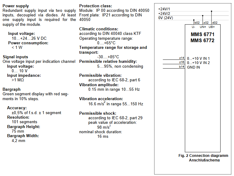
power supply
Power supply method: Redundant power supply is achieved through two power inputs, which are separated by diodes. At least one power input is required to power the module.
Input voltage: 10…+24… 26 V DC.
Power consumption:<1 W.
signal input
Each indicator channel has one voltage input.
Input voltage: 0… 10 V.
Input impedance:>1 M Ω.
bar chart
Display type: Green segment display, with red segments every 10%.
Accuracy: ± 0.5% ± 1 segment of full scale.
Resolution: 101 segments.
Bar height: 75mm.
Bar chart width: 4.2 mm.
Environment and Protection
Protection level: The module complies with the IP 00 standard of DIN 40050; The front panel complies with the IP21 standard of DIN 40050.
Climate conditions: Complies with DIN 40040 KTF grade.
Working temperature range: 0…+65 ° C.
Storage and transportation temperature range: -30….+85 ° C.
Allowable relative humidity: 5… 95%, no condensation.
Allowable vibration: in accordance with IEC 68-2 Part 6, vibration amplitude within the range of 10… 55 Hz is 0.15 mm; vibration acceleration within the range of 55… 150 Hz is 16.6 m/s ².
Allowable impact: Complies with IEC 68-2 Part 29, with a peak acceleration of 98 m/s ² and a nominal impact duration of 16 ms.
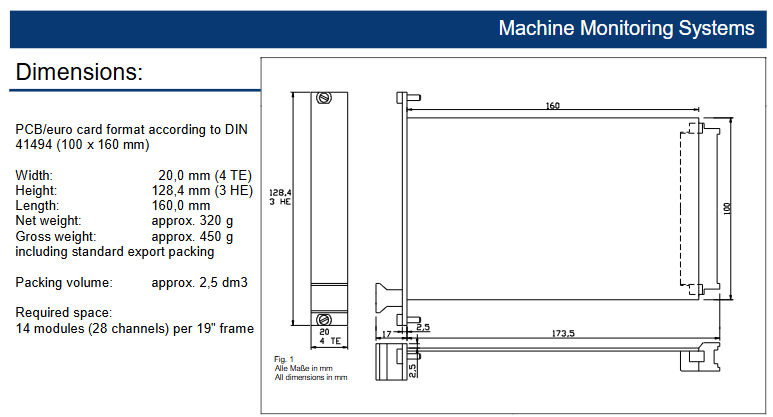
Size and weight
Size: Using PCB/European standard card format that complies with DIN 41494 standard (100 x 160 mm); Width 20.0 mm (4 TE); Height 128.4 mm (3 HE); Length 160.0 mm.
Weight: Net weight approximately 320 g; Gross weight (including standard export packaging) approximately 450 g; Packaging volume approximately 2.5 dm ³.
Space requirement: Each 19 “rack can accommodate 14 modules (28 channels).
Order Information
MMS 6771 Bar Chart Indicator (0… 100%): Order Number 9100-00067.
MMS 6772 Bar Chart Indicator (± 50%): Order Number 9100-00075.
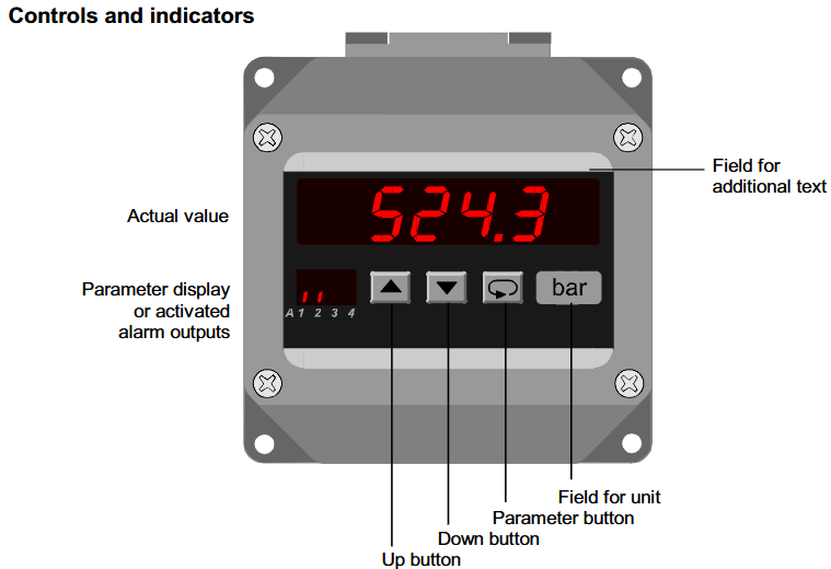
Martens Standard Signal Instrument S 1010 is designed to measure industrial standard signals of 0/4… 20mA or 0… 10VDC. It has a built-in transmitter power supply and can be directly connected to 2-wire and 3-wire transmitters (such as those used for pressure or temperature measurement). Its indication range and decimal point can be freely programmed within the range of ± 9999 (0) digits, suitable for signal measurement and monitoring in industrial sites.
Main characteristics
Display function: Equipped with a 14.2mm red LED display screen, the indication range is ± 9999 (0) digits, and the indication range and decimal point can be freely programmed.
Alarm output: Up to 2 alarm outputs, the switch performance of the alarm output can be programmed to the minimum or maximum function.
Analog output: It can generate analog output signals proportional to the input signal, including 0… 20mA/0… 10V DC, 4… 20mA/2… 10V DC. The output will automatically switch from current signal to voltage signal according to the load.
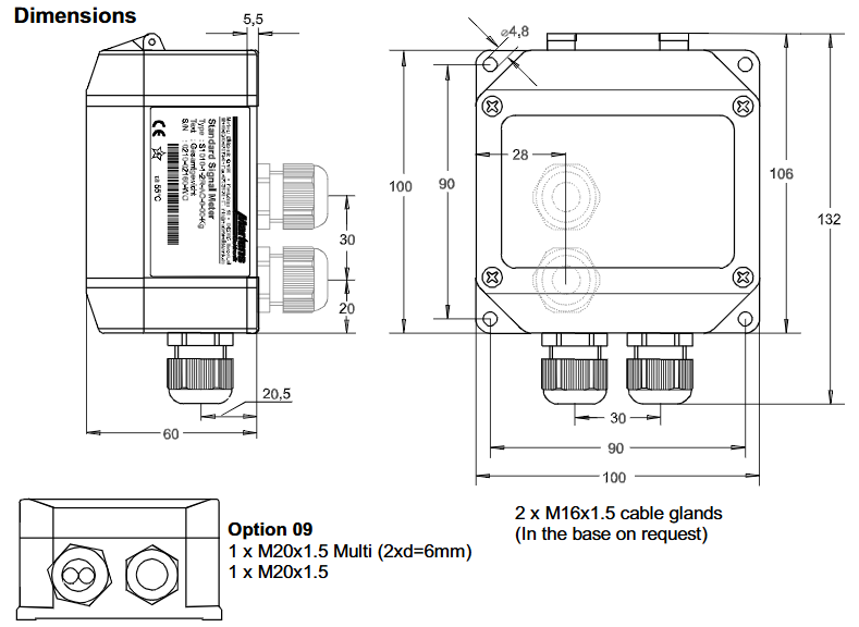
Shell and Protection: The on-site shell with snap on cover is used, equipped with 2 M16x1.5 cable glands (other specifications can refer to option 09 or customized as needed), and the protection level is IP65.
Other functions: Parameters can be programmed through the front film keyboard; Equipped with digital filtering function, it will continuously average the last 16 measurement values and display the results on the screen after activation.
Technical parameters
power supply
Power supply voltage: 230V AC ± 10%, 115V AC ± 10%, 24V AC ± 10%, or 24V DC ± 15%.
Power consumption: maximum 3.5VA, 5VA with analog output.
Working temperature: -20…+55 ° C (standard), with an extended temperature range available upon request.
Rated voltage: 250V (according to VDE 0110, between input/output/supply voltage), overvoltage category III.
Test voltage: 4kV between input/output/supply voltage.
Electromagnetic compatibility: Complies with EN55022, EN60555, IEC1000-3/4/5/11/13 standards.
input
Current input: 0/4… 20mA, Ri=10 Ω.
Voltage input: 0… 10V, Ri>100k Ω.
Accuracy:<0.1% ± 2 digits.
Temperature coefficient: 0.004%/K.
Transmitter power supply: U ₀ about 24V, Ri about 150 Ω, maximum 50mA (25mA with relay and analog output).
display
Display screen: red LED, 14.2mm.
Display range: ± 9999 (0), with leading zero suppression.
Parameter display: 2 red LEDs, 7mm (parameter and output indicator).
output
Relay: SPDT, 250V AC<250VA<2A, 300V DC<50W<2A.
Analog output: 0/4… 20mA (load ≤ 500 Ω), 0/2… 10V (load>500 Ω), not isolated from input, automatically switches output types according to load.
Accuracy: 0.1%; Temperature coefficient 0.01%/K.
other
Shell: Made of polyamide material, containing glass fiber PA6-GF15/15, keyboard made of polyester material.
Protection: IP65 (enclosure), IP20 (terminals), compliant with German BGV A2 anti touch standard.
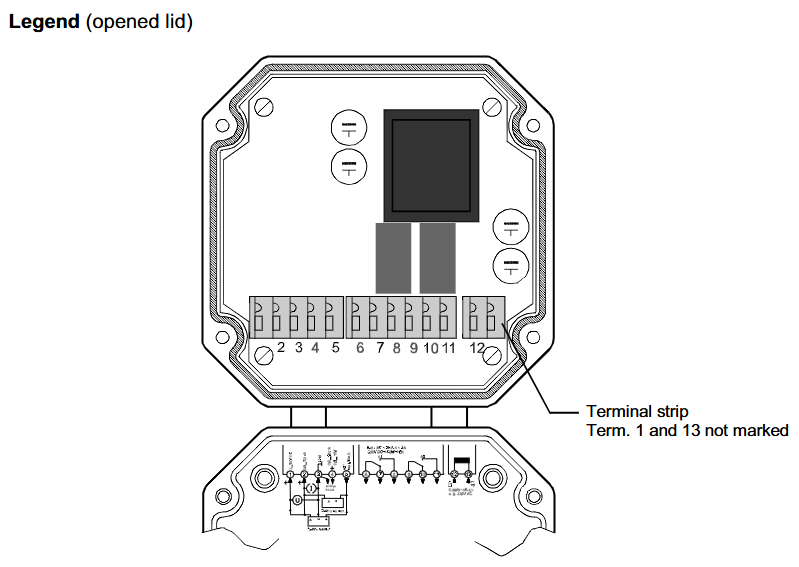
Operation and Configuration
Operation level: The device operation is divided into 2 levels. After the power is turned on, the device initializes and displays “Int”. After initialization, it enters the working level and can pre select the alarm output set point (if any). Press and hold the parameter button for more than 2 seconds to enter the configuration level of the program, where all parameters defining device functions can be programmed. If the configuration is completed or no button is pressed for more than 2 minutes, the program will return to the working level. Long press the parameter button for 2 seconds to exit the configuration level at any time.
error code
If the input signal exceeds the programmed measurement range by more than 3%, the A/D converter will be overloaded and the display screen will flash at a frequency of about 1Hz.
Error 1 “indicates an EEPROM test error. Pressing the parameter button will reload the EEPROM copy, and the device will operate according to factory settings. If the copy is invalid, the device needs to be sent to the factory for repair.
Loc “indicates program lock, refer to configuration page 7.
Parameter settings: The work level can display actual values, alarm output indicators, adjust display brightness, display maximum/minimum readings, set alarm output setpoints, etc; The configuration level can set parameters such as digital filtering, indication correction, input signal, fixed zero point, decimal point position, starting and ending values of indication range, alarm output set point, hysteresis, analog output, factory setting code, program lock, etc.
Order Code
The ordering code consists of multiple parts, representing input, alarm output, analog output, supply voltage, options, units, and additional text:
Input: 1 represents input standard signal 0/4… 20mA, 0… 10V DC, built-in transmitter power supply 24V DC maximum 50mA.
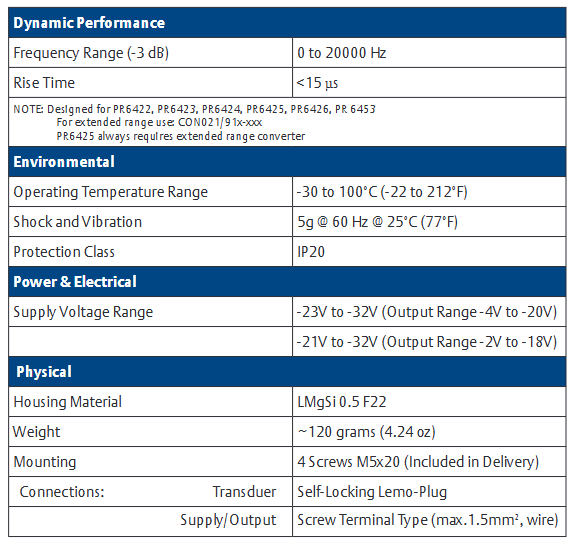
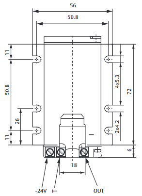
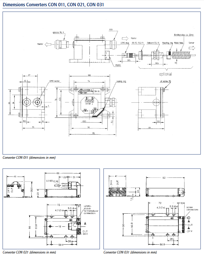
CON021 is a vortex signal converter designed specifically for critical turbomachinery applications such as steam turbines, gas turbines, water turbines, compressors, pumps, and fans, used to measure radial and axial shaft displacement, position, eccentricity, and velocity/key phase.
Main performance parameters
dynamics
Frequency range (-3 dB): 0 to 20000 Hz.
Rise time:<15 µ s.
Applicable sensors: PR6422, PR6423, PR6424, PR6425, PR6426, PR 6453; PR6425 requires the use of an extended range converter, which can be CON021/91x xxx.
environmental parameters
Working temperature range: -30 to 100 ° C (-22 to 212 ° F).
Shock and vibration: 5g @ 60 Hz at 25 ° C (77 ° F).
Protection level: IP20.
Power supply and electrical parameters
Power supply voltage range: -23V to -32V when the output range is -4V to -20V; -21V to -32V when the output range is -2V to -18V.
physical parameters
Shell material: LMgSi 0.5 F22.
Weight: Approximately 120 grams (4.24 ounces).
Installation method: 4 M5x20 screws (included upon delivery).
Connection: The sensor adopts a self-locking Lemo plug; The power/output adopts screw terminal type (maximum 1.5mm ² wire).
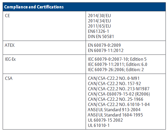
Compliance and Certification
Compliant with CE 2014/30/EU, 2014/34/EU, 2011/65/EU, EN61326-1, DIN EN 50581 and other standards.
ATEX certification: EN 60079-0:2009, EN 60079-11:2012.
The AMS 6500 Classic system is a system developed by Emerson for the protection and condition monitoring of rotating machinery. It includes multiple protection cards and can achieve comprehensive monitoring and protection of key rotating machinery such as steam turbines, gas turbines, compressors, and water turbines. It complies with international standards such as API 670 and is PlantWeb ® A part of the digital factory architecture that can be integrated with Ovation ® And DeltaV ™ Process control system integration provides machinery health status information and diagnostic tools for operators and maintenance personnel.
Introduction to Main Protection Cards
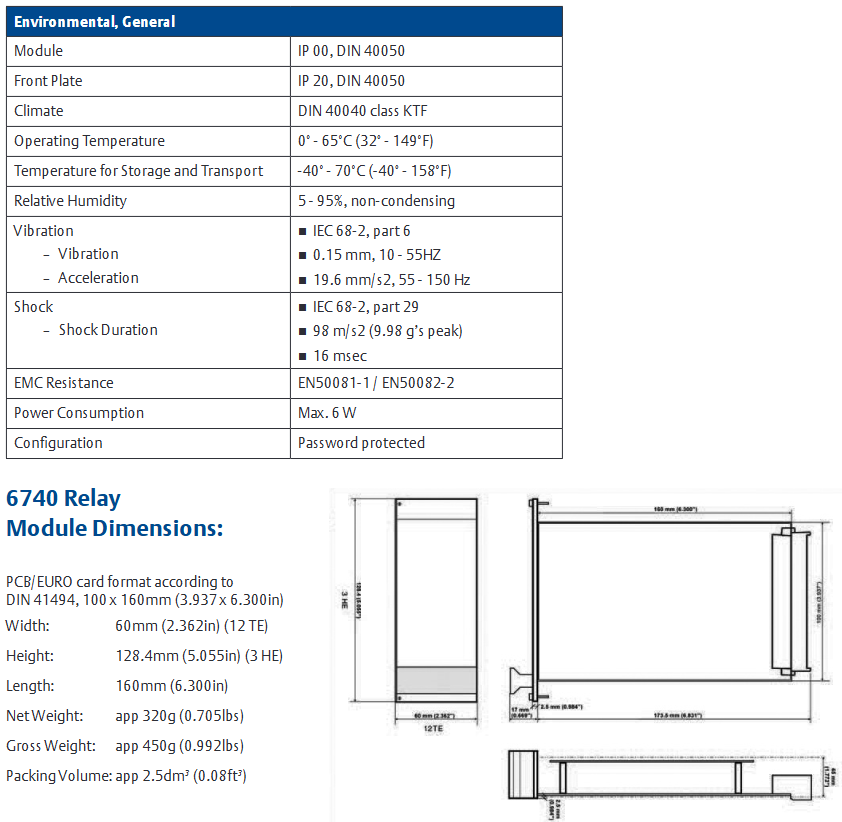
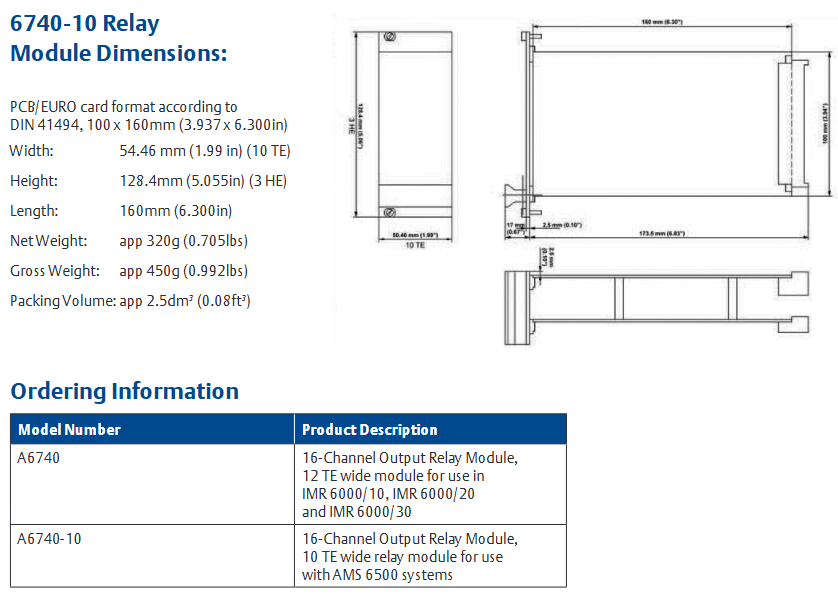
A6740/A6740-10 16 channel output relay module
Purpose: To build a complete API 670 mechanical protection monitor in conjunction with AMS 6500, which can take clear, alarm, or danger signals from any channel as input and output them from output relays through Boolean logic and time delay.
Features: 3U size, 2-slot plug-in module, compliant with API 670 standard, hot swappable; A6740 is 12TE wide and suitable for IMR6000 series racks, while A6740-10 is 10TE wide and suitable for IMR6500 series racks; It has 60 inputs, 30 logical expressions, and 16 relay outputs.
Technical parameters: The relay is a redundant and configurable mechanical relay, with a control voltage of 13-32 VDC and a contact load of 48V, 1A. It can be selected as normally open/normally closed, normally powered on/off, and single pole double throw (SPDT); Logic supports multiple types and can define up to 30 logical expressions; Time delay of 0-30 seconds.
Environment and dimensions: working temperature of 0 ° -65 ° C, storage and transportation temperature of -40 ° -70 ° C, relative humidity of 5-95% (non condensing); A6740 is 60mm wide (12TE), A6740-10 is 54.46mm wide (10TE), 128.4mm high, and 160mm long.
A6125 shell piezoelectric vibration monitor
Purpose: Used to monitor the vibration of the casing from acceleration sensors, drive alarms and relays by comparing vibration parameters with alarm settings, and protect machinery.
Features: Dual channel, 3U size, 1-slot plug-in module, compliant with API 670 standard, hot swappable; Support remote selection of limit multiples and trip bypasses; There is buffering and proportional output before and after.
Technical parameters: Two independent differential inputs, input type is piezoelectric (accelerometer or speedometer), input resistance>100 k Ω, input voltage range -5 to+15 VDC; The frequency range varies depending on the type and configuration of the sensor; The sensor is powered by a constant current of 2-8mA and 30 VDC.
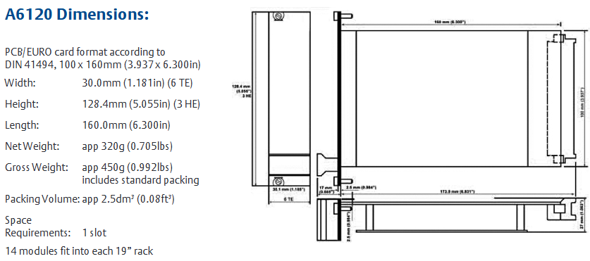
Environment and dimensions: working temperature 0 ° -65 ° C, storage temperature -30 ° -85 ° C, relative humidity 5-95% (non condensing); Width 30.0mm (6TE), height 128.4mm, length 160.0mm.
A6120 Shell Seismic Vibration Monitor
Purpose: Used in conjunction with electric seismic sensors to monitor the seismic vibration of the casing, and achieve mechanical protection by comparing vibration parameters with alarm settings.
Features: Dual channel, 3U size, 1-slot plug-in module, compliant with API 670 standard, hot swappable; Support remote selection of limit multiples and trip bypasses; There is buffering and proportional output before and after.
Technical parameters: Two independent channels, input type is electric (electromechanical), input resistance>100 k Ω, input voltage range -5-+15 VDC; Adjustable frequency range; Increase coil current by 0-8mA, configurable, with an accuracy of ± 0.5%.
Environment and size: Same as A6125.
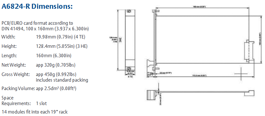
A6824/A6824-R ModBus and Rack Interface Module
Purpose: Read the parameters of all AMS 6500 modules, output through ModBus TCP/IP and/or ModBus RTU (serial), and build a complete API 670 mechanical protection monitor.
Features: 3U size, 1-slot plug-in module, compliant with API 670 standard, hot swappable; Password protected user configuration; A6824 is 6TE wide with no redundancy options, while A6824-R is 4TE wide with optional redundancy.
Technical parameters: ModBus RTU (serial) baud rate 19.2 kbaud, data bit 8, parity bit, stop bit 1; ModBus Ethernet has RJ45 sockets and 10BaseT; Default IP address 192.168.255.1, subnet mask 255.255.255.0.
Environment and dimensions: working temperature 0 ° -65 ° C, storage temperature -30 ° -85 ° C, relative humidity 5-95% (non condensing); A6824 is 30mm wide (6TE), A6824-R is 25mm wide (4TE), 128.4mm high, and 160mm long.
Other protection cards
A6620 Process Input Monitor: Four channel, monitoring process inputs such as temperature, pressure, load, etc. The input type is voltage or current, with alarm output and multiple output modes.
A6312/A6312-8 Speed and Keyphase Monitor: Dual channel, monitoring speed, phase, zero speed, and rotation direction, configurable as redundant mode.
A6630 Temperature Monitor: Multi channel, input RTD and thermocouple temperature sensors, providing temperature protection.
A6210 Thrust Position, Differential Expansion, and Rod Position Monitor: Dual channel, capable of operating in thrust position, differential expansion, or rod position modes.
A6410 Valve and Shell Expansion Monitor: Dual channel, monitoring valve position and shell expansion.
General characteristics
Most modules comply with the API 670 standard, support hot plugging, and are easy to maintain.
Equipped with self inspection function, it can monitor hardware, power input, hardware temperature, sensors, cables, etc.
Provide multiple output modes, such as 0/4-20 mA current output, 0-10 V voltage output, etc., and the output has open/short circuit protection.
Support password protection configuration to ensure system security.
Order Information
Each protection card has a corresponding model and product description, such as A6740 which is a 12TE wide 16 channel output relay module suitable for IMR 6000/10 and other racks; A6125 is a dual channel housing piezoelectric vibration monitor, etc., which can be ordered according to specific needs.
The above summary covers the purpose, characteristics, technical parameters, environment and size, and ordering information of the AMS 6500 Classic system’s main protection cards, which helps to comprehensively understand the protection card functions of the system.
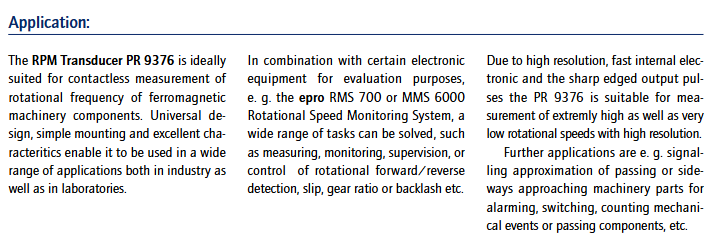
PR 9376 is an RPM sensor used for non-contact measurement of the rotational frequency of ferromagnetic mechanical components, with the following features:
The structure is sturdy, with a frequency range of 20kHz and a mechanical resolution (modulus 1) of 1.5mm. The output pulse voltage is high, and the pulse rise/fall time is only 1 µ s. The output has short-circuit protection function, and the working temperature range is -30…+100 ° C.
Widely applicable in industrial and laboratory scenarios, it can be used in conjunction with electronic evaluation equipment such as epro RMS 700 or MMS 6000 speed monitoring systems to complete measurement, monitoring, monitoring or control tasks such as rotation direction detection, slip, gear ratio, backlash, etc. It can also be used to issue proximity signals, alarms, switch control, count mechanical events, etc. Due to its high resolution, fast response internal electronic components, and sharp output pulse edges, it can measure extremely high and low speeds with high precision.
Working principle and structure
Working principle: The sensor head is a differential sensor composed of two series connected magnetic sensitive semiconductor resistors, installed above a small permanent magnet. The two resistors in the electronic part of the sensor form a Wheatstone bridge, which controls the subsequent DC switching amplifier with fast push-pull short-circuit protection output. When the trigger mark made of soft iron or steel approaches the sensor vertically, it interferes with the internal magnetic field, causing the bridge to become unbalanced and the output voltage to switch to a high level; When the trigger marker passes by, the bridge becomes unbalanced in reverse and the output signal returns to a low level. The output pulse has sharp edges and can be capacitively coupled with subsequent electronic devices even at the lowest triggering frequency.
Construction: High quality electronic circuits are packaged in a sturdy stainless steel casing, and the connecting cables are insulated with polytetrafluoroethylene. If necessary, flexible metal tubes can be added for protection.
Technical parameters
Measurement related
Measurement principle: Differential magnetic field sensor.
Trigger method: Non contact triggering through mechanical triggering of markers, with the trigger marker material being soft iron or steel.
Trigger frequency range: 20kHz.
Allowable gap: For St 37 material, it is 1.5mm.
Trigger marking size limit: standard module 1 gear (involute profile, St 37 material); Special trigger wheels need to refer to the chart.
output parameters
Output type: Short circuit protection push-pull output stage, load can be connected to measurement zero or power supply.
Output pulse voltage: Under a load of 100 (2.2) K and a 12V power supply, the high level is 10 (7) V and the low level is 1 (1) V.
Pulse rise and fall time:<1 μ s (no load and within all frequency ranges).
Power supply voltage: 8… 31.2V DC, can withstand up to 1 second without damage at 34V.
Allow ripple: 10% of the power supply voltage.
Current consumption: 25mA at 25 ° C, 24V power supply, and no load.
Mechanical and environmental parameters
Mechanical structure: stainless steel shell, encapsulated electronic circuit, sensor head material made of synthetic resin (reinforced with closed brass tube), cable insulated with polytetrafluoroethylene (optional flexible metal tube protection).
Weight: PR9376/00 with/without packaging is 330g/210g; PR 9376/20 with/without packaging is 530g/410g (both including installation kit).
Environmental conditions: reference temperature 25 ° C; operating temperature -30…+100 ° C; maximum withstand temperature (within 30 seconds, without damage) 120 ° C; storage temperature -40…+100 ° C; protection level IP 66 (compliant with DIN 40050 standard).
Other information
Reference measurement precautions: If used for reference measurement (with only one mark or collar on the shaft), relevant instructions must be followed to ensure normal operation in harsh industrial environments, a flat sensor surface, and oil and water resistant installation through standard cable sealing sleeves.
Order number: PR 9376/00 (without metal cable protection) is 9408-093 76001; PR 9376/20 (with metal cable protection) is 9408-093 76201.
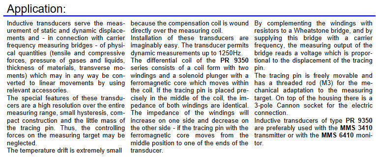
The PR 9350/.. Series linear displacement sensor is an inductive sensor mainly used to measure static and dynamic displacement, and can also be combined with carrier frequency measurement bridge to measure physical quantities that can be converted into linear motion (such as tension, pressure, material thickness, etc.). It has the characteristics of high resolution across the entire range, small hysteresis, sturdy structure, low control target force, wide measurement range (± 12 to ± 150 mm), high accuracy, and sealed packaging.
Working principle
The differential coil of the sensor consists of a coil holder with two windings and a solenoid plunger with a ferromagnetic core that moves within the coil. When the tracing needle is precisely located in the middle of the coil, the impedance of the two windings is the same; When the probe with a ferromagnetic core moves from the middle position towards one end of the sensor, the impedance of one winding will increase, while the impedance of the other winding will decrease. By using resistors to supplement the winding into a Wheatstone bridge and providing a carrier frequency to the bridge, the measured output of the bridge will obtain a voltage proportional to the displacement of the stylus. The tracing needle can move freely and comes with an M3 threaded rod for mechanical adaptation to the measurement target. There is a 3-pole Cannon socket on the top of the housing for electrical connection.
Technical parameters
Sensitivity: Within the rated measurement range, the bridge output for every 1V supply voltage is 270 mV/V.
Supply voltage: 5 Vrms.
Linear error: 2% of the total range (relative to the ± range limit of the sensor).
Carrier frequency: 3-5 kHz.
Allowable ambient temperature: -20… 0…+120 ° C.
The effect of temperature on sensitivity: 0.1%/K.
Nominal inductance: 20+20 mH when the solenoid plunger is in the middle position; 7+26 mH at maximum displacement; 13+26 mH at 50% displacement; 5+5 mH when withdrawn.
Capacitor: 250 pF per winding.
Standard attachments: Cannon MS-3106E10SL-3S connector, solenoid plunger with M3 threaded rod.
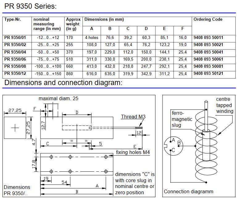
Parameters of each model
Model nominal measurement range (mm) approximate weight (g) size (mm) order code
System Overview: The PR 9376 series is a non-contact vibration and displacement measurement system based on the principle of eddy current. It consists of sensors, extension cables, and preamplifiers, and is used to monitor parameters such as shaft vibration, shaft displacement, key phase, and speed of rotating machinery. It is suitable for large rotating equipment such as steam turbines, generators, and compressors.
Core Features
By using the eddy current effect, non-contact measurement can be achieved, which is not affected by the medium and has high measurement accuracy.
The working temperature range is wide, and the sensor can operate in an environment of -30 ° C to+150 ° C. The working temperature of the preamplifier is -5 ° C to+65 ° C.
Having good linearity and stability, the linear error is usually less than 1%, and the long-term stability error is less than 0.1% per year.
Supporting multiple installation methods, radial or axial installation can be selected according to on-site requirements.
Technical parameters: The measurement range usually includes various specifications such as 0-2mm and 0-5mm; The sensitivity is generally 8mV/μ m or 4mV/μ m; The frequency response range is wide, covering 0-10kHz, meeting the measurement needs of different devices.
MMS 6000 monitoring module
Module function: The MMS 6000 monitoring module is the core component of the rotating machinery status monitoring system, which can be used in conjunction with PR 9376 series sensors to achieve real-time collection, processing, and analysis of equipment vibration, displacement, temperature, and other parameters.
Main Features
Capable of multi-channel input, capable of monitoring parameters from multiple measurement points simultaneously.
Built in multiple signal processing algorithms, capable of filtering, amplifying, integrating, differentiating, and extracting effective feature parameters from raw signals.
Support alarm function, can emit sound and light alarm signals according to preset thresholds, timely reminding operators of equipment abnormalities.
Equipped with data storage and communication functions, monitoring data can be stored locally or uploaded to the upper computer system for easy historical data query and trend analysis.
System application and precautions
Application scenario: Widely used for monitoring the status of large rotating machinery in industries such as power, petrochemicals, and metallurgy, helping users detect potential equipment failures in advance, reducing downtime, and improving equipment reliability.
Precautions
When installing sensors, it is necessary to ensure that the distance between the sensor and the object being measured is within the effective measurement range, in order to avoid affecting the measurement accuracy due to the distance being too close or too far.
The length and model of the extension cable should be selected according to the requirements of the sensor and preamplifier to ensure stable signal transmission.
Regular calibration and maintenance are required during system operation to ensure the accuracy and reliability of measurement data.
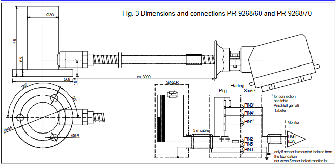
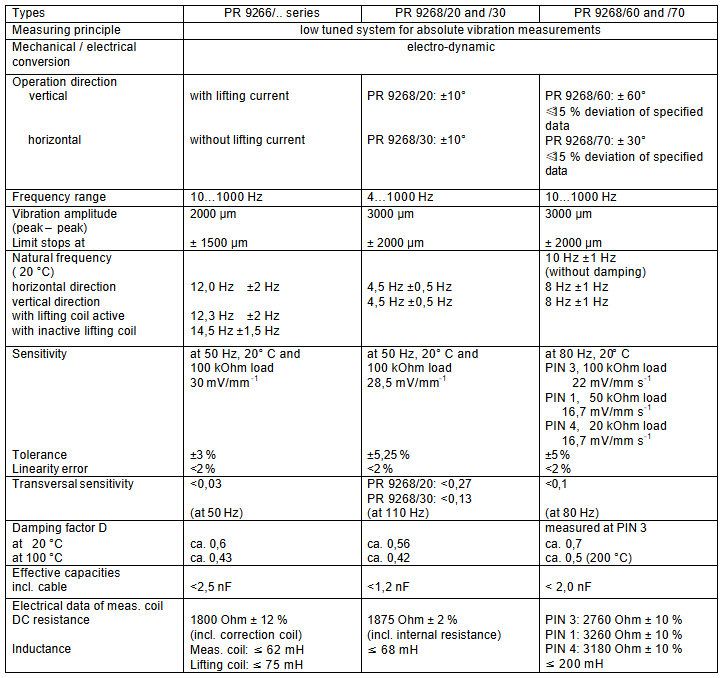
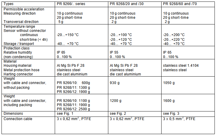
The PR 9266/.. And PR 9268/.. Series electric absolute vibration sensors are designed specifically for measuring the absolute vibration of machines and are part of the MMS 6000 and MMS 3000 rotating machinery monitoring systems. Its working temperature range can reach 200 ° C, using seismic function principle, easy installation, high sensitivity, sturdy structure suitable for industrial applications, with splash proof characteristics, protection level of IP 55 or IP 65, with two frequency ranges of 10 Hz to 1000 Hz and 4 Hz to 1000 Hz. When used in conjunction with safety barriers (Zone 1), the safety level is EEx ib II B/II C.
Application scenarios
The absolute vibration can be measured in frequency ranges of 10… 1000Hz and 4… 1000Hz, with vibration amplitudes of up to 2mm and 3mm (peak to peak), respectively. It can provide an electrical signal proportional to the vibration velocity. Suitable for various types of turbomachinery, fans, compressors, gearboxes, pumps, coal mills, and other machines. Among them, PR 9268/60 and PR 9268/70 are particularly suitable for high-temperature environments, such as gas turbine applications, and also include electrical adaptation, which can replace the original AEG Kanis Group’s MMG 033 and MMG 1033 absolute vibration sensors, and provide three different sensor sensitivities according to the type of measurement amplifier.
Functional Principles and Design
Measurement element: composed of seismic mass blocks with coils, suspended on diaphragm springs, moving in the circular gap of permanent magnets, and guided by diaphragm springs in the longitudinal direction (measurement direction) of the measurement element.
Working mode: The sensor operates above the resonance frequency (different models have resonance frequencies between 4 and 13 Hz), while the seismic mass remains stationary. Due to the vibration of the sensor housing, an electrical signal proportional to the vibration velocity is generated.
Damping: The damping of the measuring element is achieved through a damping cylinder or external device, with a damping value of about 0.6 and good linear characteristics throughout the entire frequency range.
Special design: Measurements below the resonance frequency can be corrected by corresponding amplitude response; When the vibration amplitude is too high, the mechanical limiter will reduce the maximum amplitude of the seismic system; Each sensor is designed for a measurement direction (vertical or horizontal). The PR 9266/.. Series sensor has an additional lifting coil, which adjusts the center position of the seismic element by inputting a lifting current of up to 7mA into the coil; The PR 9268/.. Series sensors can directly input the boost current into the measurement coil, but this current must be separated from the measurement signal. The measurement amplifier of MMS 6000 supports the operation of absolute bearing vibration sensors and provides boost current.
Vibration amplitude (peak to peak) and limiter position: 2000 µ m, limiter at ± 1500 µ m 3000 µ m, limiter at ± 2000 µ m 3000 µ m, limiter at ± 2000 µ m
Damping coefficient (20 ° C/100 ° C): approximately 0.6/approximately 0.43, approximately 0.56/approximately 0.42, measured at PIN 3, approximately 0.7/approximately 0.5 (at 200 ° C)
Allowable acceleration (measurement direction/lateral): 10 g continuous, 20 g short-term/5 g 10 g continuous, 20 g short-term/2 g 10 g continuous, 20 g short-term/2 g
Temperature range (sensor without connector, continuous/short time (<4h)/storage and transportation): -20…+150 ° C/-20…+170 ° C/-40…+70 ° C -20…+100 ° C/-20…+120 ° C/-40…+70 ° C -20…+200 ° C/-20…+220 ° C/-40…+70 ° C
Protection level/relative humidity (non condensing): IP 65/0… 100% IP 55/0… 100% IP 65/0… 100%
Materials (shell/metal protective hose/Hart connector): Al Mg Si Pb F 28/stainless steel/die cast aluminum Al Mg Si Pb F 28/stainless steel/die cast aluminum stainless steel 1.4104/stainless steel/die cast aluminum
Connecting cable: 3 x 0.62 mm ², PTFE, 3 x 0.62 mm ², PTFE 3 x 0.5 mm ², PTFE
Ordering Instructions
The order model format is PR 926X/X-XX0, and the meanings of each part are as follows:
The PR 9266 series corresponds to the number “6”, and the PR 9268 series corresponds to the number “8”.
Base type: 0 for no base, 1 for triangular base, 2 for cubic base.
Measurement direction: PR 9268/20 is vertical, PR 9268/30 is horizontal, PR 9268/60 is vertical (high temperature 200 ° C), PR 9268/70 is horizontal (high temperature 200 ° C).
Cable length: 0 is 3m, 1 is 5m, 2 is 8m, and 3 is 10m.
Cable end (only PR 9268/60 and/70 with Hart connector): 0 is Hart connector, 1 is open cable end.
Flexible metal protective tube: 0 with strap, 1 without strap.
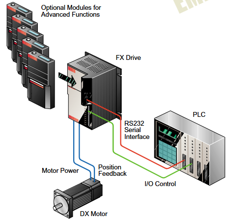
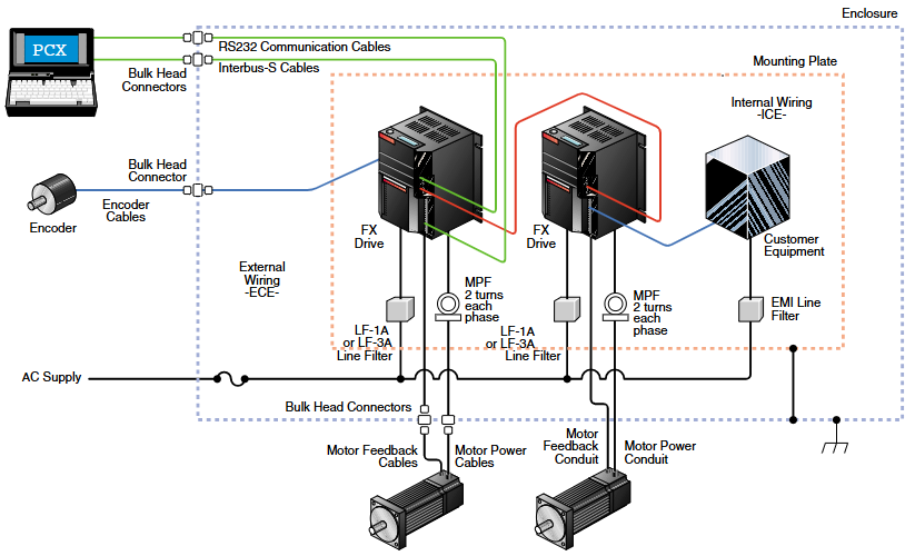
Overview of FX Series Positioning Servo Drive System
The FX series positioning servo drive system is a servo solution with over ten years of application history. By combining FX drivers with PCM modules, it can solve various common applications and is the foundation of the “Motion Made Easy” series solutions. This system is based on the 2000 Emerson Motion Control Servo Solution Catalog information and adopts a fully digital design, suitable for multiple torque ranges. It is compatible with DX series (0-120 lb in) and BL series (120-1000 lb in) rotary transformer feedback servo motors, and some models have UL certification, Canadian UL certification, and CE certification.
Core Features
Flexible power and torque: Supports multiple power inputs and can provide continuous torque from 0-1000 lb in. Some models have IP65 protection and brake versions.
Convenient programming: Use Emerson Motion Control’s PCXWin or DOS version PCX software, with fill in the blank operation for easy programming.
Rich I/O and operation modes: Standard equipped with 8 inputs and 4 output lines (10-30 VDC), supporting sinking or sourcing modes; The operating modes include integral locator, simulated speed, simulated torque, and pulse follower.
Scalability: Application modules can be installed to increase I/O, memory, and special application functions. The basic module can start up to 100 steps of motion sequence programs, and adding application modules can reach 1024 steps.
Communication and Storage: Equipped with RS-232 communication interface, with a maximum baud rate of 19.2 Kbaud, it can daisy chain up to 31 FX drives on a single communication link; Non volatile memory can store up to 32 sets of index parameters.
Other features: Supports linear or modified sine motion curves, can be scaled in user-defined units such as inches, feet, millimeters, etc., has auxiliary logic power supply to maintain critical driving information in case of bridge power loss, is equipped with LED display for displaying operation and diagnostic status, and offers a two-year extended warranty.
CE marking FX system
Certification and Scope: Compliant with EMC Directive 89/336/EEC and bearing the CE mark, with a continuous torque range of 8-120 lb in, a peak of 200%, and a maximum duration of 1.5 seconds. The amplifier is UL certified and the motor is UL approved, providing complete motion control system components.
Configuration and wiring: The CE marked FX driver has the same functionality and performance specifications as the standard FX driver, and is set using PCX programming software; There are two system wiring methods that meet CE grounding and shielding requirements, both requiring power lines and motor power filters.
Application module
The FX series offers a variety of application modules that can be easily installed on any FX driver front-end, enabling advanced positioning functions such as phase synchronization, proportional control, web control, and rotary tool cutting. It is programmed using the same PCX software as the basic FX driver, with parameters stored in non-volatile memory and movable between different drives. The main application modules include:
PCM-11 motion program controller: suitable for various applications such as composite indexing and packaging machinery.
PCM-14 slip compensator: used for slip compensation, automatic coil feeding and other scenarios.
PCM-15 proportional controller: capable of implementing functions such as flying shears and electronic spools.
Other modules, such as PCM-16 phase synchronization controller and PCM-17 random feed controller, each have their specific application areas.
Operation mode
Position control mode: The microprocessor executes user-defined motion control functions and can store multiple indexes. After adding application modules, the index storage capacity and functions can be expanded.
Pulse sequence following mode: Each received pulse generates incremental axis rotation, which can directly replace existing stepper positioning systems.
Simulation mode: includes two options: simulated speed and simulated torque, and all motion and system limitations are effective in this mode.
Software and Programming
PCX programming software: intuitive and simple, no need for advanced programming language knowledge. After the user inputs the motion parameters, the software completes the relevant operations and can complete the system settings in a short time.
Configuration and parameter settings: including driver parameter configuration, motion parameter definition (such as jogging, indexing, etc.), I/O settings, etc.
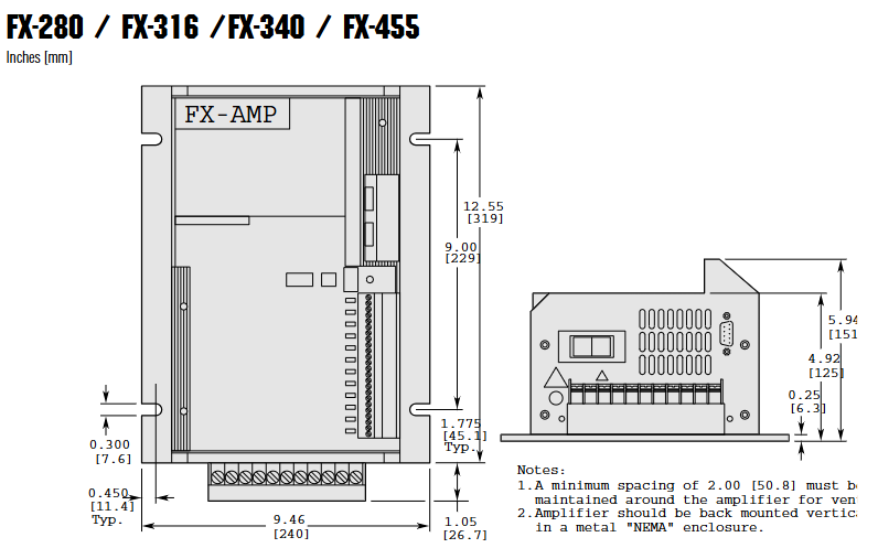
Specifications and Performance
System specifications: Different models of FX drivers have specific parameters in terms of recommended line current, motor torque, motor rotor inertia, rated power, maximum motor speed, and the shortest time to reach maximum speed.
Brake specifications: Each model of brake has clear data on maintaining torque, inertia, weight, coil voltage and current, engagement and release time, etc.
Driver specifications: including input power supply voltage, control mode, serial interface, programming method, diagnostic indicators, noise immunity, I/O circuit specifications and capacity, resolution, performance, motor housing, environmental specifications, etc.
Options and attachments
Including operator interface terminals, synchronous encoders, serial interface cables, external shunt resistors, main frequency generators, AC line filters, 525 programmable motion controllers, as well as various cables and miscellaneous accessories, it can meet different application needs.
Ovation ™ The control system is a key component of Emerson PlantWeb’s digital architecture, a distributed control and SCADA system designed specifically for the global power generation and drainage industries. It combines Emerson’s over 50 years of professional experience in complex operations control and management, and can enhance the availability, reliability, and environmental compliance of factories for users, helping to achieve operational excellence and sustainable competitive advantages.
Core advantages
Progressiveness and adaptability of technology
Using commercial off the shelf technology to provide a powerful and adaptable platform, giving users greater operational flexibility.
Support the gradual evolution of the system, which can be modified and expanded with process expansion or technological progress to avoid rapid system obsolescence and protect engineering investment.
high reliability
Build hardware platforms, operating systems, and network architectures based on industry standards to reduce maintenance costs, and the hardware can be gradually upgraded.
The controller has a fully redundant design to ensure the reliability and safety required in harsh applications.
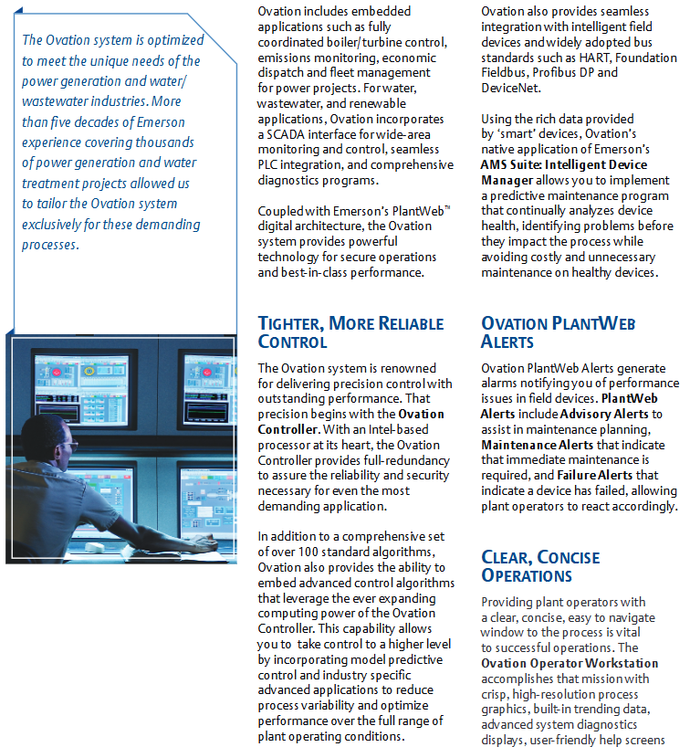
Excellent control performance
With over 100 standard algorithms and the ability to embed advanced control algorithms, it can be combined with model predictive control and industry-specific advanced applications to reduce process fluctuations and optimize performance under full range factory operating conditions.
Seamless integration with intelligent field devices and widely adopted bus standards such as HART, Foundation fieldbus, Profibus, DeviceNet, etc.
Convenient operation and programming
The operator workstation provides a clear, concise, and easy to navigate process view, including high-definition process graphics, built-in trend data, advanced system diagnostic displays, and more.
The engineer workstation provides an intuitive and easy-to-use graphical interface, and its development studio adopts drag and drop functionality and object-oriented system configuration methods to reduce the learning curve and simplify development.
System composition and functions
hardware components
Controller and I/O: A fully redundant controller and I/O component based on Intel processors, designed to be compact and modular, reducing footprint and power consumption, supporting multiple digital buses and remote I/O.
Workstation: The operator workstation adopts a ready-made desktop PC and standard Windows operating system; Engineer workstation integrates operator workstation functions and system configuration tools.
Software and Applications
Includes tools such as control builder, graphics builder, security builder, AMS suite (Intelligent Device Manager) for predictive maintenance, and OPC connectivity functionality.
Equipped with embedded applications, such as boiler/turbine coordination control and emission monitoring for power generation projects; SCADA interface and PLC integration for water supply, drainage, and renewable energy applications.
Network and Connectivity
Adopting unmodified Fast Ethernet as the control and information highway, it supports connection with almost all Ethernet devices, has multi network capabilities, and can integrate multiple Ovation systems.
Supports multiple standard data exchange protocols (such as OPC, NetDDE, ODBC, etc.) and provides direct connections with PLC and OEM control systems.
Ovation Security Center provides additional security features and services to enhance and manage system network security.
PlantWeb Architecture Integration
As a key component of PlantWeb’s digital architecture, Ovation offers a range of integrated products and features that enable asset management, process control, and management execution through intelligent field devices, industry standard platforms, and integrated modular software. The PlantWeb architecture can reduce installation costs for new projects, improve factory efficiency, and support multiple digital device communication protocols.
Applicable fields
Mainly targeting the power generation and water supply and drainage industries, it has been successfully applied in thousands of related projects and can meet the control needs of complex processes in these industries.