Call us 24/7uaedcs@163.com
Welcome to the official website of CNIACS Automation Technology Co., Ltd!
Call us 24/7uaedcs@163.com

HIMA HIMax Safety Control System

System Overview and Core Positioning

HIMax is a flexible safety control system platform launched by HIMA, designed specifically for critical production processes. Its core value lies in balancing “high safety” and “full lifecycle availability” – meeting SIL 3/PL e (some scenarios support SIL 4 CENELEC) safety level requirements, and supporting hardware/software changes during system operation (such as module replacement and program updates) without interrupting production. The system is adaptable to both centralized and distributed applications, and can be flexibly configured based on I/O points, response time, and fault tolerance requirements. It covers a full range of scenarios from small safety applications (such as single machine interlocking) to large complex systems (such as oil and gas pipeline control), and is typically used in safety critical areas such as emergency shutdown (ESD), fire and gas monitoring (F&G), and high pressure protection (HIPPS).

Core advantages and technological highlights

(1) Full lifecycle availability design

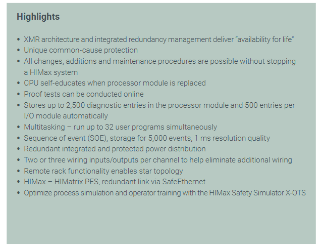
Continuous operation capability

Adopting XMR (eXtended Modular Redundancy) architecture and integrated redundancy management, key modules (such as CPU and system bus) support hot plugging and can be replaced without downtime;

The CPU module has a “self-learning function” that automatically adapts to system configuration after replacement, reducing manual intervention time;

Online Proof Test: supports testing of safety functions during operation without the need to pause production, in compliance with IEC 61508 standard requirements.

Flexible scalability and compatibility

Modular design: Supports applications ranging from small (X-CPU 31 module) to large (X-CPU 01 module), with flexible expansion of I/O points through the expansion rack. A single system can support a maximum of a large number of I/O channels;

Cross system integration: Establish redundant links with HIMatrix controllers through SafeEthernet, support remote rack deployment in star topology, and adapt to distributed factory layouts;

Historical data storage: The processor module can store 2500 diagnostic records, and each I/O module can store 500 records. The SOE (Sequence of Events) function supports storing 5000 events with a resolution of 1ms, making it easy to trace faults.

(2) Security and Performance Assurance

Security Design and Certification

Safety level: Complies with SIL 3 (IEC 61508/61511), PL e (EN ISO 13849-1), and some scenarios (such as railway and maritime) have passed SIL 4 certification (EN 50126/50129);

Explosion proof and environmental adaptability: Supports explosion-proof standards such as ATEX Zone 2 (T4), IEC Ex Zone 2 (T4), UL Class I Div 2, and can withstand tropical environments (ANSI/ISA-S 71.04 Class G3). The working temperature range covers industrial scene requirements;

Common cause fault protection: Reduce the risk of common cause faults through hardware isolation and software redundancy algorithms, ensuring that a single fault does not affect the system’s safety functions.

High performance control capability

Multi tasking: supports running 32 user programs simultaneously, meeting the segmented control requirements of complex processes;

Fast response: The resolution of the sequence of events (SOE) is 1ms, the accuracy of analog processing (such as 4-20mA signals) is high, and it is suitable for high-speed control scenarios (such as turbine machinery control TMC);

Dual logic support: Simultaneously compatible with both “De energy to trip” and “Energize to trip” safety control logics, adapted to different industry safety standards.

Hardware module classification and key parameters

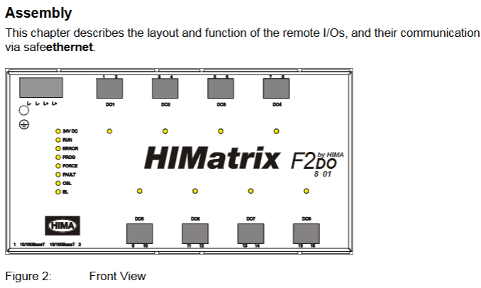
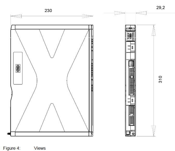
The HIMax module is divided into a central module and an input/output (I/O) module, with a unified size of 310 × 29 × 230mm for easy rack installation and replacement. The core module functions are as follows:

(1) Central module (control and communication core)

Module type, model, core function, applicable scenarios

The processor module X-CPU 01 has high performance, supports complex control algorithms, and has redundant configurations for large systems and critical controls such as HIPPS and TMC

Lightweight design of processor module X-CPU 31, cost optimized for small and medium-sized safety applications such as single machine interlocking and fire and gas monitoring

The system bus module X-SB 01 manages system bus communication and supports redundant buses (dual module configuration) for all systems, ensuring reliable bus communication

Communication module X-COM 01 has 4 RJ-45 interfaces, 2 9-pin D-Sub interfaces, and supports 6 protocol systems for communication with third-party devices (such as PLC, HMI, SCADA)

(2) I/O module (signal acquisition and control execution)

Digital Input Module

Covering multiple voltage levels and functional requirements, the core models are as follows:

X-DI 64 01/51: 64 channel 24VDC, 01 type supports SIL 3, 51 type is standard;

X-DI 32 01/02/03/04/05: 32 channels, supporting 24VDC (SIL 3), 8.2VDC (proximity switch+line monitoring, SIL 3), 48VDC (SIL 3), 24VDC (with SOE, SIL 3), 8.2VDC (proximity switch+line monitoring+SOE, SIL 3) respectively;

X-DI 32 51/16 01:32 channel 8.2VDC (standard type), 16 channel 120VAC (SIL 3), compatible with different types of field sensors.

Analog Input Module

Focusing on industrial standard analog signals, supporting isolation and monitoring functions:

X-AI 16 51:16 channel, supports 0/4-20mA, ± 280mV signals, galvanic isolation, compatible with thermocouples (TC) and Pt100 temperature sensors;

X-AI 32 01/02/51: 32 channels 4-20mA, Type 01 with line monitoring (SIL 3), Type 02 with line monitoring+SOE (SIL 3), Type 51 is standard.

Counter module

X-CI 24 01/51:24 channel, maximum counting frequency 20kHz, 01 type supports SIL 3, 51 type is standard, suitable for speed and pulse counting scenarios (such as encoder signal acquisition).

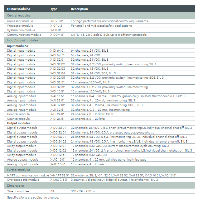
Digital/Relay Output Module

Emphasize safety control and fault monitoring:

X-DO 32 01/51:32 channel 24VDC/0.5A, 01 type with short circuit monitoring+single channel shutdown (SIL 3), 51 type with output protection+group shutdown;

X-DO 24 01/02:24 channels, supporting 24VDC/0.5A (line monitoring+single channel shutdown, SIL 3) and 48VDC/0.5A (line monitoring+single channel shutdown, SIL 3) respectively, SIL 3);

X-DO 12 01/51:12 channel 230VAC/DC, 01 type with current measurement+cycle counting (SIL 3), 51 type is standard type;

X-DO 12 02:12 channel 24VDC/2A, equipped with short circuit monitoring and single channel shutdown (SIL 3), suitable for high-power loads.

analog output module

X-AO 16 01/51:16 channel 4-20mA, 01 type supports paired galvanic isolation, 51 type is standard, used to control actuators such as valves and frequency converters.

Special function module

X-HART 32 01:32 HART modems, supporting cooperation with X-AI/X-AO series modules to achieve HART protocol communication (SIL 3);

X-MIO 7/6 01: Overspeed trip module, including 3 counter channels, 4 digital inputs, 5 digital outputs, and 1 relay channel (SIL 3), suitable for turbine and motor overspeed protection.

Software and Programming Support

(1) Programming Tools and Languages

Adopting the HIMA unified engineering tool SILworX, it supports multiple programming methods that comply with the IEC 61131-3 standard:

Function Block Diagram (FBD): intuitive drag and drop programming, suitable for logic control;

Sequential Function Diagram (SFC): used for sequential control scenarios (such as step flow);

Structured Text (ST): a high-level programming language suitable for complex algorithms;

C code (optional): Meets customized control requirements and requires HIMA certification.

(2) Communication Protocol and Integration Capability

The X-COM 01 communication module supports running 6 protocols simultaneously, covering security and standard communication requirements:

Safe communication: SafeEthernet (HIMA safety protocol, used for redundant communication between systems), PROFIsafe (industrial safety protocol);

Standard communication: OPC DA/A&E, Modbus TCP (master/slave), PROFINET, PROFIBUS DP (master/slave), Modbus RS485 (master/slave), TCP/UDP transceiver, SNTP (time synchronization);

Customized communication: ComUserTask (CUT), supports user programming of custom protocols (RS422/RS485 interface), HART over IP (supported by V7 version), compatible with third-party smart devices.

Compliance certification and typical applications

(1) Global Compliance Certification

The system has passed multiple international safety and industrial standard certifications, covering major global market demands:

Safety standards: IEC 61508(SIL 3)、IEC 61511(SIL 3)、EN ISO 13849-1(PL e)、EN 62061(SIL 3)、EN 50126/50129(SIL 4);

Industry standards: EN 298 (Burner Control), EN 54-2 (Fire Alarm), NFPA 72/85/86 (North American Fire and Boiler Standards), ANSI/ISA-84.00.01 (Process Safety);

Explosion proof and Environmental Protection: ATEX Zone 2(T4)、IEC Ex Zone 2(T4)、UL 508、CSA-C22.2 No.142、FM Class I Div 2、Achilles Level I( Network security);

Special fields: DNV (Maritime), Lloyd’s Register (Classification Society), Russia EAC (Russian Market), ABS (Marine Equipment Certification).

(2) Typical application scenarios

Process industry: Emergency Shutdown System (ESD), Fire and Gas Monitoring System (F&G), High Voltage Protection System (HIPPS), Pipeline Management and Control (PMC);

Energy and Power: Turbomachinery Control (TMC), Boiler Protection and Burner Control System (BCS);

Transportation and infrastructure: railway level crossing control, rail vehicle safety control;

General industry: equipment interlocking, safety door control, robot protection.

Summary

The HIMax system is centered around “safety and reliability,” “flexible scalability,” and “full lifecycle availability.” Through modular hardware, redundant architecture, multi protocol support, and comprehensive certification, it has become an ideal safety control platform for critical production processes. It not only meets strict safety standards, but also reduces downtime losses through uninterrupted operation and maintenance, online testing, and other designs, adapting to the full scenario requirements of complex systems from small and medium-sized to large. It is widely used in industries such as petrochemicals, energy, and transportation that require high safety and availability.

HIMA HIMatrix F2 DO 8 01 Remote I/O Module

Safety regulations and environmental requirements

(1) Core security requirements

Expected use and protective measures

The module is a SELV/PELV safety ultra-low voltage device, which poses no direct danger to itself. For use in Ex areas (such as Zone 2), additional explosion-proof requirements must be met (such as installation in enclosures with protection levels above IP54);

ESD protection: Only personnel with knowledge of electrostatic protection are allowed to operate. ESD wristbands should be worn during work, and when idle, they should be stored in anti-static packaging to avoid static electricity damaging the internal circuits of the module.

Residual risk and emergency response

Residual risk sources: engineering design defects (such as wiring errors), user program vulnerabilities (such as failure to configure fault safety logic), hardware failures (such as relay adhesion), which need to be avoided through compliant configuration and regular testing;

Emergency principle: The module is an integral part of the safety system, and in the event of a malfunction, all outputs must be switched to the “power-off safety state” (such as relay disconnection). It is prohibited to perform operations that obstruct the safe operation of the system in emergency scenarios (such as forcibly activating outputs).

(2) Environment and installation conditions

Specific parameter specifications for the required type

The protection level IP20 (IEC 60529) needs to be installed inside the control cabinet to prevent dust and condensation. Ex Zone 2 requires additional enclosure protection

If the working temperature exceeds 0…+60 ° C, it needs to be downgraded to avoid oxidation of relay contacts and overheating of the circuit

Storage temperature -40…+85 ° C must be met during transportation or idle to avoid component damage

Pollution level II (IEC/EN 61131-2) is applicable to non-conductive dust environments to avoid short circuit risks

Evaluation of heat dissipation and insulation performance is required in high-altitude areas with an altitude of less than 2000 meters

Supply voltage 24 VDC (-15%…+20%) ripple factor ≤ 15%, requires independent power supply (recommended PELV/SELV power supply), equipped with 10A delay fuse

Product Description and Core Features

(1) Basic characteristics of module

Functional positioning and compatibility

Role: As a remote I/O, unable to run user programs independently, requiring SafeEthernet to receive controller instructions and expand the digital output interface of the HIMax/HIMatrix system;

Safety certification: certified by T Ü V, supporting SIL 3(IEC 61508/61511/62061)、Cat. 4(EN 954-1)、PL e(EN ISO 13849-1), Simultaneously comply with explosion-proof and industrial standards such as ATEX Zone 2 and UL 508;

Model difference: Divided into “F2 DO 8 01 (adapted to ELOP II Factory, part number 98 2200407)” and “F2 DO 8 01 SILworX (adapted to SILworX, part number 98 2200481)”, the hardware is the same, only the software adaptation is different.

Core Components and Security Design

Relay output circuit: Each output is equipped with 2 forced guide contact safety relays and 1 standard relay, with a built-in 3.15A fuse (limiting switch current to 60% of rated value, in compliance with VDE 0116), and the contacts support 250 VAC/250 VDC voltage, which can be used for safe shutdown control;

Fault response mechanism: When an output fault is detected (such as relay adhesion or abnormal voltage), only the corresponding output is cut off for a single fault, and all outputs are cut off for an overall module fault. At the same time, the ERROR LED is activated and a fault code is reported;

Self testing function: supports MOT (maintenance testing) and FTT (fault tolerance time) testing, can detect safety switches, relay voltage, temperature thresholds, etc., to ensure output reliability.

(2) Hardware Structure and Interface

Core parameters

|Category | Parameter Value | Description|

|——|——–|——|

|Output channel | 8 channels | Each independent relay, normally open contact (NO), potential isolation|

|Output capacity | 250 VAC/250 VDC, maximum 3 A | Switching life under Ohmic load ≥ 3 × 10 ⁶ times|

|Communication Interface | 2 × RJ-45 (SafeEthernet) | Supports 10/100 Base-T, auto negotiation rate/duplex, auto crossover (no need for crossover)|

|Supply current | Maximum 0.6 A | 24 VDC supply, power dissipation 18-46 W (depending on load)|

|Dimensions (H × W × D) | 114 × 207 × 86 mm (including fasteners) | Weight approximately 1.3 kg, supporting 35 mm DIN rail installation|

Grouping and meaning of LED indicator lights

There are 4 sets of LEDs in the front-end of the module, which perform a full light test when powered on. The status meanings of each indicator light are as follows:

Working voltage light (24 VDC, green): normally on indicates normal power supply, off indicates no voltage;

System lights (red/yellow, multiple lights):

Red light (ERROR): Constant light indicates that the module has entered the ERROR STOP state (such as hardware failure), slow flashing indicates loading the operating system;

Yellow light (Initiat/STOP/RUN): Constant light indicates corresponding status, slow flashing indicates loading configuration or forced function activation;

Communication light (green/yellow next to RJ-45): Green light constantly on indicates full duplex, flashing indicates conflict; A constant yellow light indicates a normal physical connection, while a flashing light indicates data transmission;

I/O light (DO 1-8, yellow): normally on indicates that the output is powered on (relay is engaged), and off indicates that the output is powered off (safe state).

Reset button function

Reserved reset hole in the upper left corner of the module (triggered by an insulating pin), only used for scenarios where the administrator account is forgotten or the IP address does not match: When restarting, press and hold the reset button for ≥ 20 seconds to restore the default parameters (IP: 192.168.0.99; SRS: 60000.200.0 (SILworX)/60000.0.0 (ELOP II Factory)), and clear the user account (only the default administrator account is retained, password is empty).

Installation and configuration process

(1) Module installation and wiring

Installation prerequisites

It needs to be fixed on a 35 mm DIN rail with reserved heat dissipation space around it (high power dissipation, avoid being adjacent to heating equipment);

Ex Zone 2 installation requires additional requirements: enclosure protection level ≥ IP54 (compliant with EN 60529), enclosure must be labeled with a “power off operation only” warning, equipped with a 10A delay fuse, PELV/SELV power supply, and reference to EN 60079-15 standard (terminal wiring, creepage distance, etc.).

Wiring specifications

Power wiring: Connect the positive terminal of the 24 VDC module to the “+” terminal and the negative terminal to the “-” terminal. It needs to be powered independently to avoid being in line with the power circuit;

Relay output wiring: Each output corresponds to 2 terminals (such as DO1 corresponding to terminal 1/2, A/B contacts), which are normally open contacts. The load needs to be equipped with external fuses according to the voltage type (DC loads require additional anti reverse protection);

Communication wiring: The RJ-45 interface is connected to a SafeEthernet network, supporting daisy chain topology, and requires the use of CAT 5e or higher shielded cables (shielded layer single ended grounding to reduce interference).

(2) Software configuration configuration

SILworX configuration (version ≥ 7)

Core Parameters (Module tab):

Basic parameters: Configure module name, IP address, subnet mask (default 192.168.0.99), SRS (system rack slot address, default 60000.200.0);

Fault monitoring: Enable MOT/FTT testing, configure temperature threshold (output cut-off in case of overheating), read fault codes (e.g. 0x0001 indicates module fault, 0x0400 indicates first level overheating).

Channel configuration (DO 8: Channels tab): Assign global variables to each output (DO1-DO8), set output values (1=power on, 0=power off), and monitor single channel faults (such as 0x10 indicating relay 1 feedback error).

ELOP II Factory configuration (version<7)

Assign system signals to output channels through the “Signal Editor”, with configuration parameters similar to SILworX. The core difference lies in the signal mapping method (based on “signal name channel” association rather than variable allocation), and the fault code is consistent with the state definition (such as Mod. Error Code 0x0010 indicating configuration error).

Operation, maintenance, and troubleshooting

(1) Daily operation and diagnosis

operation monitoring

Real time status can be viewed through LED: the RUN light is always on to indicate normal operation, the ERROR light is on to indicate a fault, and the I/O light corresponds to the output status;

Detailed diagnosis: Read fault logs (such as relay adhesion, communication interruption) through programming tools, support online viewing of output feedback values (ensure that instructions are consistent with actual status).

Common faults and solutions

|Fault phenomenon | Possible causes | Troubleshooting steps|

|All outputs are unresponsive (all I/O lights are off) | 1 The module has not entered the RUN state; 2. Power supply failure; 3. Communication interruption | 1 Check the system light (whether it is in RUN state); 2. Measure 24 VDC power supply; 3. Check the Ethernet light (whether there is a physical connection)|

|Single output fault (ERROR light on, fault code 0x10) | 1. Relay 1 feedback error; 2. Contact adhesion | 1 Power off and restart module; 2. Check the load circuit (whether there is a short circuit); 3. Module replacement verification|

|Communication interruption (communication light off) | 1 IP address conflict; 2. Cable malfunction; 3. Controller offline | 1 Check if the module IP and PADT are on the same network segment; 2. Replace the communication cable; 3. Confirm whether the controller is operating normally|

(2) Maintenance and Lifecycle Management

regular maintenance

Operating system update: Utilize system downtime to load the latest version of the operating system through programming tools (modules must be in STOP state), and backup configuration before updating to avoid data loss;

Proof Test: Conducted every 10 years, the test includes relay output on/off, fault response (such as simulating overheating), and communication link integrity. Refer to the HIMA Safety Manual (HI 800 023 E).

Scrap and transportation

Scrap: Industrial users need to dispose of modules containing electronic components in accordance with environmental protection requirements. They can contact HIMA to sign a scrap agreement, which prohibits the arbitrary disposal of modules containing electronic components;

Transportation/Storage: Original anti-static packaging should be used to avoid mechanical impact, and the storage temperature should be maintained at -40…+85 ° C to avoid humid environments.

Key terms and compliance

Core Terminology

SafeEthernet: The HIMA secure communication protocol ensures the safety of data transmission between the controller and remote I/O (compliant with SIL 3 requirements);

SRS (System. Rack. Plot): Module addressing method used to locate the position of remote I/O in the system (default 60000.200.0);

MOT (Maintenance Test): Maintenance testing to check the hardware status of safety relays, feedback loops, etc;

FTT (Fault Tolerance Time): The maximum time a module can maintain a safe state after detecting a fault.

Compliance certification

The module complies with multiple international standards, and core certifications include:

Safety standards: IEC 61508 (SIL 3), IEC 61511 (SIL 3), EN ISO 13849-1 (PL e);

Explosion proof standards: ATEX Zone 2 (EN 60079-15), UL Class I DIV 2;

Industrial standards: UL 508, NFPA 79, EN 54-2 (fire alarm).

HIMA HIQuad X Safety System

System Overview and Positioning

HIQuad X is a programmable electronic safety system launched by HIMA. As an upgraded version of the HIQuad system with over 30 years of application history, it integrates mature HIQuad I/O technology and high-performance HIMax system architecture, suitable for scenarios with strict safety requirements and the need to ensure system availability (such as process industries and energy fields). The system supports centralized and distributed deployment, and is compatible with various I/O modules including intrinsically safe SIL 3 modules. It is programmed using SILworX engineering tools to meet safety function requirements such as “de energize to trip” and “energize to trip”.

Typical application scenarios

HIQuad X is mainly aimed at process industries and safety critical fields, with typical applications including:

Continuous and batch production equipment: safety interlock control for chemical reaction vessels and pharmaceutical production lines;

Burner and boiler protection: realize safety functions such as flame monitoring, emergency shutdown due to overheating and overpressure;

Oil and gas pipelines: pressure and flow anomaly detection and emergency cutoff control;

Other industrial scenarios that require compliance with SIL 3 safety level, such as nuclear power auxiliary systems and safety monitoring in petrochemical storage tank areas.

Core advantages

(1) System level advantages

Improvement of engineering and operation efficiency

Adopting the Unified Engineering Platform (SILworX) to reduce the cost of switching between multiple tools;

Support fast reload of application programs, hardware configurations, and communication parameters to shorten fault recovery time;

Optimize diagnostic functions (such as real-time monitoring of module status and fault location prompts) to reduce maintenance and troubleshooting difficulties.

Performance and flexibility optimization

Shorten the system cycle times and improve real-time control response speed;

Accelerate REAL data computation efficiency to meet high-precision process control requirements;

Supporting a hybrid architecture of single loop (Mono) and redundant loop, flexibly adapting to different availability requirements, and reducing device footprint;

Supports multitasking and can run up to 32 applications simultaneously, meeting the requirements for complex control logic splitting.

Security and compatibility guarantee

Continuing HIMA’s mature safety concept and meeting the highest SIL 3 safety level requirements;

Compatible with 24 existing HIQuad I/O modules, no need to replace I/O hardware or field wiring during upgrades, reducing renovation costs and downtime;

F-CPU 01 operates without interference with the I/O module, avoiding mutual influence between core control and signal acquisition;

Cross connection between modules is supported to enhance system redundancy and availability.

(2) Highlights of modernization upgrade

Compared to traditional systems, HIQuad X has significant advantages in upgrade scenarios:

Shorter transformation cycle: No need to redeploy I/O wiring, reducing on-site construction workload;

High hardware reuse rate: directly compatible with existing HIQuad I/O modules, reducing upgrade costs;

Enhanced scalability: supports longer system buses, better electromagnetic compatibility (EMC stability), and adapts to complex industrial environments;

Optimization of operating experience: Improved tactile feedback design (such as module insertion and removal feel, button operation feedback) enhances operational convenience.

System architecture and core parameters

(1) Differences between two major system models

The HIQuad X is divided into two models, H51X and H41X, with core configuration differences as shown in the table below:

Model: Maximum I/O Expansion Rack Number, Single System: Maximum I/O Module Number, Applicable Scenarios

H51X 16 with 256 large complex systems (such as large petrochemical parks and centralized control of multiple units)

H41X 1 set of 28 small and medium-sized systems (such as single production line, independent equipment safety control)

(2) Key components and functions

Component model type, core functions and parameters

The F-CPU 01 processor module is suitable for H51X/H41X, including 2 RJ-45 interfaces, supporting SIL 3 safety level, and implementing core control logic operations

The F-COM 01 communication module integrates Ethernet, Profibus DP, and serial communication functions, including 2 RJ-45 interfaces and 1 9-pin D-Sub interface (including 2 RS 485 channels), supporting both secure and standard protocols

F-IOP 01 I/O processing module SIL 3 level, with redundant system bus, responsible for I/O signal acquisition and control instruction execution

F-PWR 01 power module outputs 24 VDC/5 VDC, with a power of 50 W, suitable for the main power supply of H41X/H51X systems

F-PWR 02 (optional) watchdog power module is only suitable for H51X expansion rack, ensuring stable power supply for expansion units

F-BASE RACK 01 basic rack 19 inch specification, 4U height, suitable for H51X system

F-BASE RACK 02 basic rack 19 inch specification, 4U height, including 12 I/O module slots, suitable for H41X system

The F-FAN 01 system fan has a 19 inch specification and a height of 1U, providing heat dissipation for the rack and ensuring stable operation of the module

Communication function and protocol support

(1) Advantages of Communication Architecture

Hardware and connectivity flexibility

Both F-CPU 01 and F-COM 01 are equipped with two Ethernet interfaces, supporting redundant communication;

F-COM 01 supports up to 10 modules to establish interference free point-to-point connections with F-CPU 01, expanding communication capacity;

Support the use of complete IP address segments, configurable subnet masks and virtual local area networks (VLANs) to achieve network segmentation isolation and enhance communication security.

Secure Communication and System Interconnection

Implementing secure communication between HIMA systems through the SafeEthernet protocol, supporting secure integration of HIQuad X with HIMax, HIMatrix systems, and RIO (Remote I/O);

Integrate HIPRO-S V2 protocol to establish secure connections with existing HIQuad F 8627X systems, ensuring compatibility during upgrades of older systems;

Support PADT (Programming and Debugging Tool) to communicate with the system through SILworX, enabling program download and diagnosis.

Classification of supported communication protocols

The communication protocols of HIQuad X are divided into “safety related protocols” and “standard protocols”, which are implemented through different modules:

Protocol type supports the core purpose of protocol implementation module

Secure communication protocols SafeEthernet, HIPRO-S V2, SNTP (time synchronization) F-CPU 01/F-COM 01 for secure data transmission, time synchronization, and interconnection with legacy HIQuad systems

Standard communication protocols Modbus TCP (master/slave), Profibus DP (slave), Modbus RTU (master/slave), COM User Task (CUT, custom protocol programming) F-COM 01 and third-party devices such as SCADA systems HMI、 Non safety data exchange of smart meters

Compliance and Certification Standards

HIQuad X complies with multiple international safety and industrial standards, ensuring compliant applications in different regions and industries worldwide. Core certifications include:

Safety integrity standards: IEC 61508 (maximum SIL 3), IEC 61511 (maximum SIL 3 for process industries), EN ISO 13849-1 (maximum PL e);

Industry specific standards: EN 50156 (railway applications), EN 298 (burner control), EN 12067 (oil and gas pipelines), EN 54-2 (fire detection and alarm), NFPA 72/85/86 (North American fire and boiler standards);

Explosion proof standard: EN 60079-15 (ATEX Zone 2, non explosion proof area);

Network security standard: IEC 62443 (SL1, to be published).

Summary

As an upgraded version of the HIMA safety system, the core value of HIQuad X lies in * * “balancing safety and availability, upgrading and compatibility” * *: it not only meets the highest SIL 3 safety level requirements, but also improves system availability through flexible architecture, fast reloading, and optimized diagnostics; Simultaneously compatible with existing HIQuad I/O modules and communication protocols, significantly reducing the cost of upgrading old systems, suitable for various industrial scenarios that require high safety and efficiency.

HIMA HIMax X-SB 01 System Bus Module

Safety regulations and environmental requirements

(1) Core security requirements

Expected use and protective measures

The module is used to assemble safety related controller systems and must comply with SELV/PELV safety ultra-low voltage standards. Additional explosion-proof measures must be taken for use in Ex areas;

ESD protection: Only personnel with knowledge of electrostatic protection are allowed to operate. ESD wristbands should be worn during work, and when idle, they should be stored in anti-static packaging to avoid damage to the module caused by static electricity.

Residual risk and emergency response

Residual risk sources: engineering design defects, user program errors, wiring faults, which need to be avoided through compliant configuration and regular testing;

Emergency principle: The module is a component of the safety system, and in the event of a malfunction, the system must enter a safe state (such as emergency shutdown). It is prohibited to perform operations that obstruct the safe operation of the system in emergency situations.

(2) Environment and installation conditions

Specific parameter specifications for the required type

The protection level IP20 (IEC 60529) needs to be installed inside the control cabinet to prevent dust and condensation water

If the working temperature exceeds 0…+60 ° C, it needs to be downgraded to avoid module overheating

Storage temperature -40…+85 ° C must meet this range during transportation or idle use

Pollution level II (IEC/EN 61131-2) is applicable to non-conductive dust environments

Evaluation of heat dissipation and insulation performance is required in high-altitude areas with an altitude of less than 2000 meters

Supply voltage 24 VDC (-15%…+20%) ripple factor ≤ 5%, requires independent power supply

Product Description and Core Features

(1) Basic characteristics of module

Functional positioning and compatibility

Slot 1 and Slot 2 can only be inserted into the HIMax motherboard, supporting two operating modes:

Single module (Mono mode): Only one system bus works;

Dual module (Redundancy mode, recommended default): 2 redundant system buses to improve availability;

Safety certification: certified by T Ü V, supporting SIL 3(IEC 61508/61511/62061)、Cat. 4(EN 954-1)、PL e(EN ISO 13849-1), Data transmission adopts security related protocols.

Fault response mechanism

If a system bus fails, the redundant bus will automatically take over communication (dual modules need to be pre configured) to ensure uninterrupted data transmission; The module has built-in self detection function, which can identify hardware/software faults and power supply abnormalities. Fault information is displayed through LED indicator lights and SILworX diagnostic interface.

(2) Hardware Structure and Interface

core component

Security related processor system: 1oo2 architecture (1 out of 2), controls and monitors a single system bus (Slot 1 corresponds to bus A, Slot 2 corresponds to bus B), the operating system and fault logs are stored in non-volatile memory and can be read through SILworX;

Interface configuration:

Number of Interface Types, Functions, and Parameters

PADT service interface 1 connects to programming and debugging tools (10/100 Base-T, does not support automatic crossover, point-to-point requires crossover, IP address can be configured)

System bus interface (Up/Down) 2 connects to other baseboards (supports automatic crossover, requires CAT 5e or above Ethernet cable, RJ-45 interface)

Diagnostic interface (Diag) 1 reserved for future expansion use

Grouping and meaning of LED indicator lights

There are a total of 6 sets of LEDs on the front end of the module, and a full light test will be conducted when powered on. The status meanings of each indicator light are as follows:

Module status indicator lights (Run/Error/Stop/Init):

Run (green): Constant light indicates normal operation (RUN state), slow flashing (600ms on/600ms off) indicates STOP/OS_SOWNLOAD state;

Error (red): Constant light/slow flashing indicates detection of internal faults (such as hardware failure, power supply abnormality);

Stop (yellow): Constant light indicates STOP/valid configuration, slow flashing indicates STOP/invalid configuration;

Init (yellow): Constant light indicates Initiate initialization, slow flashing indicates LOCKED locked state.

Redundant indicator lights (Ess/Red):

Ess (yellow): Always on indicates single bus operation (removing modules can cause system failure), slow flashing indicates redundant configuration but backup modules are unavailable;

Red (yellow): Always on indicates redundant operation (bus ID synchronization successful), off indicates no redundancy.

Other indicator lights: Rack connection light (Up/Down, green/yellow indicates physical/logical connection status), Slot light (3-18, green indicates slot has module and connection is normal), Ethernet light (PADT/Up/Down/Diag, green flashing indicates data transmission, yellow indicates speed/duplex mode).

​(3) Key technical parameters

Category parameter values

Maximum power supply current 0.65 A

Dimensions (H × W × D) 310 × 29.2 × 230 mm

Weight approximately 1.2 kg

Maximum relative humidity of 95% (without condensation)

Installation and configuration process

(1) Module installation and removal

Installation prerequisites

It is necessary to cooperate with the dedicated connector board on the motherboard (slot 1 on the left board and slot 2 on the right board), and label the number of supported slots (10/15/18 slots) and slot IDs on the connector board;

It is necessary to install matching fan components to ensure forced heat dissipation (refer to the HIMax system manual). The time to open the fan bracket cover during operation should be less than 10 minutes to avoid heat dissipation failure.

Operation steps

Installation: Open the fan bracket cover → Insert the top of the module into the hook guide → Rotate the module downwards until it locks into place → Tighten the fixing screws → Close the cover and lock it;

Disassembly: Open the cover plate → Loosen the screws → Rotate the module upwards to detach from the guide rail → Remove the module → Close the cover plate.

(2) SILworX configuration configuration

Core Parameters (Module tab)

Network parameters: configure IP address, subnet mask, default gateway, rate mode (recommended automatic negotiation), flow control mode (recommended automatic negotiation);

Safety related parameters:

MAC Learning: Default “Conservative” (ARP cache locking for at least one aging cycle to prevent ARP spoofing), “Tolerance” mode is suitable for scenarios that require fast updates of MAC addresses;

ICMP mode: default “Echo Response” (supports ping testing, balancing security and diagnosis), “No ICMP Responses” has the highest security but cannot ping detect.

Routing Configuration (Routing tab)

Supports up to 8 routing entries, requiring configuration of destination IP address, subnet mask, and gateway for cross network communication (such as connecting to other baseboards or external devices).

Operation, Maintenance, and Lifecycle Management

(1) Daily operation and diagnosis

operation monitoring

The module does not require direct operation and can be remotely controlled through the PADT tool. The running status can be viewed in real-time through the LED (such as the Run green light indicating normal), and detailed fault information (such as IP address conflicts and bus interruptions) can be read on the SILworX diagnostic interface.

Fault handling

Common faults: IP address conflict (PADT and H/F/Col lights flashing slowly at the same time) → Reconfigure IP; Bus transient interference (Up/Down lights flashing slowly) → Check cable connection or replace CAT 5e cable;

Initialization phase fault: If the fault still reports after initialization (such as the Error light being constantly on), it is necessary to check the module power supply, configuration parameters, or replace the module.

(2) Maintenance and scrapping

regular maintenance

Operating system update: Load the latest version of the operating system during system downtime (modules need to be in STOP state, refer to SILworX online help);

Proof Test: It needs to be performed every 10 years to ensure that the module’s safety functions are functioning properly (see HIMax Safety Manual HI 801 003 E for detailed procedures).

Transportation, storage, and scrapping

Transportation/Storage: Original factory packaging (anti-static and flame-retardant) is required to avoid mechanical impact and static electricity;

Scrap: Industrial users need to dispose of modules containing electronic components in accordance with environmental protection requirements. They can contact HIMA to sign a scrap agreement, which prohibits the arbitrary disposal of modules containing electronic components.

KOLLMORGEN Saia PCD Series I/O Modules

Basic Information

Core scope

Covering five major categories of modules: digital input/output modules, analog input/output modules, digital hybrid I/O modules, counting and motion control modules, and special function modules (such as weighing and thermocouple modules), while distinguishing the differences between PCD2 and PCD3 series modules (such as the addition of cage spring terminals and higher anti-interference levels in PCD3), supporting industrial standard signal types such as 24V DC/115-230V AC input and 0-10V/0-20mA analog signals. Some modules have electrical isolation (up to 500V isolation voltage) and short-circuit protection functions.

Version and compatibility

Document historical version updates focus on module function supplementation (such as adding PCDx.B160/W380/G200 modules in ENG07), parameter correction (such as adjusting product status section in ENG09), and the latest version of ENG10 optimizes PCD3.A810/W800 power consumption parameters; In terms of hardware compatibility, the PCD2 module needs to be compatible with CPU hardware version H or above, while the PCD3 module supports RIO remote IO systems (some modules such as H210/H31x are currently not compatible).

Core module classification and technical parameters

(1) Core parameters of PCD2 series modules

1. Digital input module

Module model, number of input channels, signal range, response time, electrical isolation, wiring method

PCD2.E110 8 24V DC 8ms without 10 pole screw terminal

PCD2.E160 16 24V DC 8ms without 34 pole ribbon cable connector

PCD2.E500 6 115-230V AC 10ms (pull in)/20ms (release) with (2.5kV optocoupler isolation) 10 pole screw terminal

PCD2.E610 8 24V DC 10ms with (1kV AC isolated) 10 pole screw terminal

2. Digital output module

Module model, output channels, rated current signal range, protection function

PCD2A300 6 2A/channel 10-32V DC without short circuit protection, requires external 12.5A fast melting

PCD2.A400 8 0.5A/channel 5-32V DC without short circuit protection, load resistance ≥ 48 Ω

PCD2.A200 4 2A/channel (relay) 250V AC/50V DC varistor+RC component contact protection

PCD2.A410 8 0.5A/channel 5-32V DC electrical isolation (1kV AC), without short circuit protection

3. Analog input module

Module model, channel number, resolution, signal type, accuracy (25 ℃)

PCD2.W100 4 12 bit 0-10V/-10~+10V ± 0.1% ± 1LSB

PCD2.W220 8 10 bit Pt/Ni1000 temperature sensor ± 3LSB

PCD2.W305 7 12 bit 0-10V ± 0.15%

PCD2.W745 4 16 bit J/K type thermocouple ± 0.4 ℃ (0-100 ℃)

4. Counting and motion control module

Module model, function, highest frequency, number of axes, encoder support

PCD2.H100 pulse counting 20kHz incremental encoder (phase A/B)

PCD2.H150 SSI interface 500kHz 1 absolute encoder (SSI protocol)

PCD2.H210 stepper motor control 19.45kHz 1 24V DC encoder

PCD2.H310 servo motor control 100kHz 1 24V DC incremental encoder

(2) Core Upgrade of PCD3 Series Modules

The PCD3 series optimizes terminal design, anti-interference performance, and functional expansion based on PCD2, with the following core differences:

Module type: PCD2 series features: PCD3 series upgrade points

The screw terminal of the digital input module (with a maximum wire diameter of 1.5mm ²) has added cage spring terminals (such as 24 pole terminals for E165, supporting a wire diameter of 1.0mm ²), and the anti-interference level has been raised to IEC 61000-4-4 (± 2kV capacitive coupling)

The 8-bit resolution of the analog output module is mainly increased from the W6x0 series to 12 bit resolution, with an output delay of ≤ 10 μ s and support for -10~+10V bipolar signals

The motion control module only supports local IO H32x series, supports DSP processors, realizes S-curve trajectory planning, and supports 250kHz encoder input

Wiring compatibility only supports fixed terminals, supports PCD3.K010/K106 connection cables, and modules can be directly cascaded (maximum distance of 2.5m)

(3) Electrical isolation and safety characteristics

Isolation type and level

Digital isolation module (such as PCD2. E610/PCD3. E610): using optocoupler isolation, isolation voltage 1000V AC (1 minute), no isolation between channels, suitable for strong interference environments (such as near frequency converters);

Analog isolation module (such as PCD2. W3x5/PCD3. W3x5): adopts DC/DC isolation, isolation voltage of 500V, supports 7-channel analog signal acquisition, suitable for signal isolation in process control (such as chemical equipment).

Safety Specifications

High voltage modules (such as PCD2, E500, PCD3, E500115-230V AC input) need to be separately equipped with fuses (1A/250V), and are prohibited from being connected together with low voltage signals (≤ 50V);

The contact protection of relay output modules (such as A200/A210) needs to be matched with the load type: inductive loads require external current diodes, and capacitive loads require series current limiting resistors to avoid contact arc damage.

Installation and wiring specifications

(1) Mechanical installation requirements

Installation environment

Working temperature: 0-55 ℃ (if it exceeds 40 ℃, the output current should be reduced by 2% for every 1 ℃ increase);

Protection level: IP20 (IEC 60529), to be installed inside the control cabinet to avoid dust and condensation water;

Installation spacing: Reserve ≥ 25mm heat dissipation space on both sides of the module for vertical installation (allowing ± 15 ° tilt), and additional fixation is required for heavy-duty modules (such as PCD2. H32x).

Terminal installation

Screw terminal: torque 0.7-0.8Nm (compatible with M3 screws), wire diameter 0.5-2.5mm ²;

Cage type spring terminal (PCD3 specific): No tools required, directly insert the wire (maximum 1.0mm ²), press the release button when pulling out, and increase wiring efficiency by 30%.

(2) Key specifications for electrical wiring

Power supply and grounding

Digital module: 24V DC power supply needs to be supplied separately (ripple ≤ 10%), PE wire cross-section ≥ 1.5mm ², single point grounding is used (grounding resistance ≤ 1 Ω);

Simulation module: The signal ground and power ground are wired separately, and the analog signal cable adopts twisted pair shielded wire (single end grounding of the shielding layer) to avoid parallel connection with the power cable (spacing ≥ 200mm).

Typical wiring example

Digital input (source wiring): PCD2.E110 module E0-E7 is connected to the sensor signal,+24V is connected to the positive pole of the external power supply, and the negative pole of the sensor is connected to the module GND. The LED lights up to indicate that the input is valid;

Analog output (current type): PCD3.W410 module A0 connected to actuator (such as valve positioner), external 24V DC power supply positive pole connected to actuator, negative pole connected to module A0 terminal, select 4-20mA signal range through jumper;

Isolation module: The PCD2.E610 module needs to be separately connected to a 24V isolation power supply, and the signal end should be completely isolated from the PLC system ground to avoid common ground interference.

Function configuration and programming support

(1) Hardware configuration

Address setting

Digital module: Set the CANopen station address (1-99) and baud rate (10-1000kbit/s) through the DIP switch on the front-end of the module. After setting, restart the 24V power supply to take effect;

Expansion card configuration: Multifunctional modules such as PCD2.G410 need to be plugged into a communication expansion card (such as a PROFIBUS card) through Slot 1/2, and the module will automatically recognize it after power on. If it is not recognized, the locking status of the card buckle needs to be checked.

Signal filtering

Digital input: Select the filtering time through the internal jumper of the module (such as PCD2.E111 supporting 0.2ms/8ms switching), and select a short filtering time for high-frequency signals (such as encoders);

Analog input: PCD3.W380 supports software configuration of digital filtering (50/60Hz notch filtering) to suppress power grid interference, with a filtering time constant of 2.4ms.

(2) Software Configuration (PG5 Environment)

tool support

Saia PG5 software (version ≥ 2.3) is required to configure module parameters through the “Device Configurator”:

Motor configuration: Select the motor model (such as AKM series servo motor), automatically load rated current, inductance and other parameters, and execute “Motor Probe” to optimize the current loop gain;

Safety configuration: The STO function needs to be associated with a safety controller and set a periodic testing interval (≤ 8 hours, meeting SIL CL3 requirements);

Linearization of analog signals: The PCD2-W745 thermocouple module requires the selection of thermocouple type (J/K type), and the software automatically compensates for the cold junction temperature (compensation accuracy ± 0.2 ℃).

Programming Example

Counting function: PCD2.H100 reads the counting value through the IL command “RD-DIGIAL-IO-0TO15”, and sets “WR-DIGIAL-OUTPUT0TO15” to trigger the counter reset;

Servo control: PCD2.H310 sets the target position through the FB function block “MC_SoveAbsolute”, and the parameter “Position” is filled in with the number of pulses (to match the electronic gear ratio).

Troubleshooting and Maintenance

(1) Common faults and solutions

Troubleshooting steps for possible causes of fault phenomena

No response to digital input (LED not lit) 1. Power supply not working; 2. Loose wiring; 3. Input signal exceeds the range. 1. Measure the 24V voltage at the X4A terminal of the measurement module; 2. Re tighten the terminal screws (torque 0.8Nm); 3. Check the sensor output (e.g. NPN sensor needs to output a low level)

Simulated output deviation exceeds tolerance 1. Calibration parameters are lost; 2. Load impedance mismatch; 3. Signal distortion caused by interference. 1. Perform “Analog Calibration” through PG5 to recalibrate; 2. Confirm load resistance: voltage output ≥ 3k Ω, current output ≤ 500 Ω; 3. Add shielding layer grounding (single ended grounding)

Relay output contact adhesion: 1. Load current exceeds the set value; 2. Contactless protective components; 3. Frequent switching: 1. Measure the load current (such as A200 maximum 2A/channel); 2. Inductive load connected in parallel with 1N4007 freewheeling diode; 3. Reduce switching frequency (recommended ≤ 10 times/minute)

The frequency of the counting module is abnormal. 1. The encoder cable is too long; 2. Signal interference; 3. Improper setting of filtering time: 1. Cable length ≤ 10m (signal repeater is required for over distance); 2. Use twisted pair shielded wires (with the shielding layer grounded); 3. Set the filtering time to 1/5 of the signal period (e.g. 10 μ s for a 20kHz signal)

(2) Regular maintenance project

Standard requirements for maintenance project cycle operation content

Terminal inspection every quarter: 1. Tighten screw terminals (torque 0.7-0.8Nm); 2. Clean the terminal dust and ensure that the terminal is free from oxidation and looseness, with a contact resistance of ≤ 10m Ω

Module temperature monitoring: 1. Measure the temperature of the heat sink every month; 2. Check the fan speed (e.g. PCD2.H32x fan ≥ 2500rpm), the temperature of the heat sink is ≤ 75 ℃, and the fan has no abnormal noise

Calibration verification every six months: 1. Analog input: Input standard signal (such as 5V/10mA), read module values; 2. Analog output: Set 50% output, measure actual value deviation ≤ ± 0.5% (if exceeded, recalibration is required)

Monthly safety function testing: 1. Trigger the STO function and check if the motor torque is cut off; 2. After testing the safety relay contacts and activating STO, the motor has no torque, and the contact response is ≤ 10ms

Product lifecycle and spare parts management

Product status classification

The manual specifies the status of modules “Active”, “Outphased”, and “Repair phase”:

The maintenance period for discontinued modules (such as PCD2.G400/G410) is until December 31, 2018, and there will be no spare parts supply thereafter;

Alternative solutions: Replace PCD2.W100 with PCD2.W380, and PCD2.H222 with PCD3.H222.

Recommended spare parts list

It is recommended to reserve 1-2 sets of key spare parts, with the following matching models:

Module type/common model/spare part model

Digital input module/PCD3.E110/PCD3.E111 (compatible and responsive)

Analog output module/PCD2.W410/PCD3.W410 (terminal upgrade)

Relay module/PCD2.A200/PCD3.A200 (same function, higher anti-interference)

Counting module/PCD2.H100/PCD3.H110 (maximum frequency increased to 100kHz)

Kollmorgen S700 series digital servo amplifier

Basic Information

Core positioning: The S700 series is a high-performance digital servo amplifier that supports 208-480VAC three-phase input (S7xx0 model) or 110-230VAC single/three-phase input (S7xx6 model), integrates CANopen and EtherCAT bus interfaces, and comes standard with dual channel STO (Safe Torque Off) function (up to SIL CL3/PLe level). Additional functions such as PROFIBUS, SERCOS, DeviceNet can be achieved through expansion cards. It is recommended to use it with Kollmorgen motors and direct connection to loads is prohibited for operation.

Version and hardware adaptation: The document corresponds to hardware version 02.20 and requires firmware version ≥ 5.18 (ND1/NDO data structure). The functional differences between different hardware versions mainly lie in DC bus parallel capability and memory compatibility (support for memory cards at 02.10 and above). For older versions (such as 00.20/01.21), reference should be made to the corresponding manual revision.

Core technical characteristics and classification of amplifiers

(1) General Technical Parameters

Category parameter item specification

Power characteristic input voltage S7xx0:3 × 208V-10%~3 × 480V+10% (50/60Hz); S7xx6:1×110V-10%~3×230V+10%(50/60Hz)

The maximum DC bus voltage is 900VDC (S7xx0) and 455VDC (S7xx6), with an undervoltage fault of 100VDC and an overvoltage fault of 900VDC (S7xx0)/455VDC (S7xx6)

Rated output current of 1.5-24ARMS (e.g. S70102 is 1.5ARMS, S72402 is 24ARMS), peak value of 4.5-72ARMS (lasting for 2 seconds)

Motor adaptation motor types: synchronous servo motor, asynchronous motor, DC motor, linear motor

Motor inductance range S7xx0 (320VDC bus): 50-200mH; S7xx6 (160VDC bus): 7-30mH

Feedback supports rotary transformers, SinCos encoders (EnDat 2.1/2.2, BiSS-C, HIPERFACE), incremental encoders (ROD), SSI encoders

Control characteristic switch frequency 8kHz (output stage)

Control cycle current loop 62.5 μ s, speed loop 62.5 μ s, position loop 250 μ s (optional 125 μ s)

Safety function dual channel STO (SIL CL3/PLe), supporting extended safety functions such as SS1/SS2/SOS/SLS (requires safety expansion card)

Environmental adaptability: Operating temperature range of 0-40 ℃ (rated working condition), with a reduction of 2.5%/℃ required for 40-55 ℃

Storage temperature -25-70 ℃

Humidity 95% relative humidity (no condensation)

Altitude ≤ 1000m (no downgrading), downgrading 1.5%/100m for 1000-2500m

Protection level IP20 (IEC 60529)

(2) Model classification and key parameters

The S700 series is divided into two sub series based on rated output current and input voltage, with the following differences in core parameters:

Subseries models rated output current (ARMS) peak output current (ARMS/2s) input voltage DC bus voltage (VDC) weight (kg) heat dissipation method

S7xx0 (three-phase input) S70102 1.5 4.5 3 × 208-480VAC 900 4.4 Forced air cooling

S70302 3 9 3 × 208-480VAC 900 4.4 forced air cooling

S70602 6 18 3 × 208-480VAC 900 4.4 forced air cooling

S71202/S7120S 12 24/30 3 × 208-480VAC 900 5.5 forced air cooling

S72402/S7240S 24 48/72 3 × 208-480VAC 900 5.5 forced air cooling

S7xx6 (single/three-phase input) S70162 1.5 4.5 1 × 110-230VAC/3 × 110-230VAC 455 4.4 Forced air cooling

S70362 3 9 1 × 110-230VAC/3 × 110-230VAC 455 4.4 Forced air cooling

S70662 6 18 1 × 110-230VAC/3 × 110-230VAC 455 4.4 Forced air cooling

S71262/S7126S 12 24/30 1 × 110-230VAC/3 × 110-230VAC 455 5.5 forced air cooling

S72462/S7246S 24 48/72 1 × 110-230VAC/3 × 110-230VAC 455 5.5 forced air cooling

(3) Optional configurations and expansion cards

Core Function Expansion

Security Expansion Card: Slot 3 can be installed with S3 (S1-2, SIL CL3/PLe) or S4 (S2-2, SIL CL2/PLd) security cards, supporting security functions such as SS1/SS2/SOS/SLS/SPLP. The S3 card also supports safety brake control (SBC) and brake testing (SBT).

Communication expansion card: Slot 1 supports PROFIBUS(DE-106712)、SERCOS(DE-90879)、DeviceNet(DE-103571)、SynqNet(DE-200073),Slot 2/3  Supports PosI/O (DE-200881) to expand high-precision I/O interfaces.

Feedback extension card: FB-2to1 (DE-201664) supports simultaneous connection of digital primary feedback and analog secondary feedback, solving compatibility issues with multiple feedback devices.

Heat dissipation optimization: Option F2 (Slot 2/3) is a controllable fan that automatically adjusts the speed based on temperature (55-75 ℃) and braking power (20-45W) to reduce noise (default fan noise is 43-65dB (A)).

Storage and Communication: Supports MMC/SD memory cards (DE-201257), which can store firmware and parameters, enabling fast configuration of multi axis systems; Standard RS232 (X6), CANopen (X6), EtherCAT (X7) interfaces, EtherCAT supports CAN over EtherCAT protocol and automatically detects bus type.

Installation and wiring specifications

(1) Mechanical installation requirements

Installation preparation

Installation surface: It should be made of conductive material (such as galvanized steel plate) with a flatness error of ≤ 0.1mm. It should be fixed with M5 hexagon socket screws (torque 0.7-0.8Nm). The installation size of S701-S712 is 345 × 70 × 243mm (H × W × D), and S724 is 348 × 100 × 243mm. A heat dissipation space of ≥ 25.4mm should be reserved around it. It is prohibited to install it under a heat source (such as a frequency converter).

Temperature control: If the ambient temperature exceeds 40 ℃, forced air cooling (wind speed ≥ 2m/s) should be added. When the temperature of the heat sink exceeds 80 ℃, the amplifier will overheat and shut down (fault F01). It is recommended to use the S724 model with a cold plate (heat dissipation area ≥ 0.1m ²).

Fan installation

S701-S712 fan: Pinch the long side of the fan housing and pull it down. When installing, align it with the green connector and push it into the buckle lock.

S724 fan: Pinch the short side of the fan housing and pull it down. When installing, make sure the connector is aligned with the socket and press it until the buckle is fixed. The fan has no independent wiring and can be powered through the internal connector.

(2) Electrical wiring specifications

Wiring safety and sequence

Power off operation, ensure capacitor discharge (≥ 8 minutes after power off, measure DC bus voltage<60V), all power cables (motor/power) and control cables (feedback/I/O) need to be separately shielded, and the shielding layer should be grounded 360 ° through the amplifier front panel or metal connector (low impedance).

The distance between power cables and control cables should be ≥ 200mm to avoid cross interference; When the length of the motor cable exceeds 25m, Kollmorgen 3YL/3YLN motor choke coils should be connected in series (such as S70102 with 4 × 1mm ² cable) to reduce leakage current and EMI interference.

Core interface definition

Power interface (X0): S7xx0 model L1/L2/L3 connected to three-phase live wire, PE connected to protective ground; S7xx6 single-phase connection L1/N, three-phase connection L1/L2/L3, PE wire section ≥ 10mm ² or dual PE wiring, external slow melting fuse needs to be configured (such as S70102 with 6A/600V, S72402 with 30A/600V).

Motor interface (X9): U2/V2/W2 is connected to the three-phase winding of the motor, PE is connected to the motor casing, BRAKE+/BRAKE – is connected to a 24V brake (only with a brake motor), the brake current is ≤ 2A, and a separate freewheeling component (such as a varistor) needs to be configured.

Safety interface (X4A/X4B): STO1 Enable (X4B/6) and STO2 Enable (X4A/3) are connected to external safety circuits (24V/33-40mA). In dual channel configuration, safety relay outputs need to be connected separately to ensure SIL CL3 level. When not in use, they need to be short circuited to+24V.

Feedback interface (X1/X2): X2 is the rotary transformer interface (9-pin SubD), R1/R2 is the reference signal, S1/S2/S3/S4 is the sine/cosine signal; X1 is an encoder interface (15 pin SubD) that supports protocols such as EnDat/BiSS/HIPERFACE. The FBTYPE parameter needs to be selected based on the feedback type (e.g. EnDat 2.2 is set to 32/34).

Typical wiring scheme

Three phase power supply (S70602): L1/L2/L3 connected to 3 × 400VAC, PE connected to cabinet ground, X0 terminal tightened with a torque of 0.7-0.8Nm, power supply side connected in series with 10A slow melting fuse (UL class RK5) to avoid damage from surge current.

Motor and brake (with brake motor): X9 terminal U2/V2/W2 is connected to the motor winding, BRAKE+is connected to 24V power supply, BRAKE – is connected to amplifier X9/1, the brake control wire uses shielded twisted pair (such as 2 × 0.75mm ²), the shielding layer is grounded at both ends, and additional mechanical braking is required for vertical axis applications (brake is only used for parking and frequent braking is prohibited).

STO safety circuit (dual channel): STO1 Enable (X4B/6) is connected to the normally closed contact of safety relay K1, STO2 Enable (X4A/3) is connected to the normally closed contact of safety relay K2, and the relay coil is controlled by the emergency stop button. When the emergency stop is triggered, the STO signal is disconnected, and the amplifier cuts off the motor torque (fault F27).

Security Features and System Configuration

(1) STO security function (core security feature)

Function definition and level

STO (Safe Torque Off) achieves no torque output of the motor by blocking the triggering pulse of the power transistor, which complies with EN 60204-1 stop category 0 (uncontrolled shutdown). The single channel configuration (STO1/STO2 series) reaches SIL CL2/PLd, and the dual channel+cycle test (safety controller monitoring feedback signal) reaches SIL CL3/PLe. The PFH_D is 1.04E-09 1/h, and the MTBF is 20 years.

Wiring and Testing

Single channel wiring: STO1 Enable and STO2 Enable are connected in series and then connected to a safety relay output. The reference ground is XGND (X4B/5), with an input voltage of 20-30VDC and a current of 33-40mA. When disconnected, the amplifier displays “- S -” and the motor has no torque.

Functional testing:

When the motor is stationary (the enable signal is valid), disconnect the STO input, the amplifier should immediately cut off the torque, display fault F27, and the BTB/RTO contact (X3B/14-15) is disconnected.

Reset STO input, use Fault Reset input (X3A/18) or software reset to restore the amplifier to normal state, with a test cycle of ≤ 8 hours (SIL CL3 requirement).

(2) System configuration (software and hardware settings)

Software Configuration (DRIVE GUI. EXE)

Installation and Connection: Supports Windows 2000/XP/Vista/7, connects PC and amplifier X6 interface through RS232 cable (P7S2-232-9D), baud rate 38400bps, data bit 8, even check, stop bit 1, software automatically recognizes amplifier model and firmware version.

Core configuration module:

Motor configuration: Select the motor model (such as AKM series) from the database, or manually input parameters such as rated current, torque constant, inductance, etc., and perform the “Motor Probe” to detect the motor inductance and optimize the current loop gain.

Security configuration: The STO function requires setting the STO Status output (such as X3A/6) and associating it with the security controller through the ASCII command OxMODE70 to achieve periodic testing; The security card S3/S4 needs to be configured with SS1 activation signal (X30/1) and reset signal (X30/20) to ensure the correct triggering timing of the security function.

Sports configuration: Set the electronic gear ratio for the position ring (e.g. set PGEAR1=2 and PGEAR0=1 for a 1:2 gearbox), gain for the speed ring (Kp=0.5-2.0, Tn=0.01-0.1s), and automatically optimize control parameters through “Autotuning” to reduce tracking errors (fault F03).

Hardware switch configuration

Address and baud rate: Set the CANopen station address (1-99) and baud rate (10-1000kbit/s) through the amplifier front-end buttons. After setting, restart the 24V power supply to take effect. The baud rate encoding is as follows: “25” corresponds to 250kbit/s, and “50” corresponds to 500kbit/s.

Expansion card recognition: After inserting the expansion card into Slot 1/2/3, the amplifier will automatically recognize it when powered on. The function can be configured through the DRIVE GUI “Expansion Card” interface (such as setting the PROFIBUS address to 3 and the baud rate to 1.5Mbit/s). If the expansion card is not recognized, it is necessary to check whether it is installed properly (card buckle locking).

KOLLMORGEN P70360 High Performance Microstep Driver

Basic Information

Core positioning: P70360 is an AC input micro stepper driver that supports 120/240 VAC power supply, with a maximum output current of 2.5 A RMS (peak 3.5 A RMS) and integrated Dynamic Smooth ™ (Dynamic smoothing) Multi-Stepping ™ (Multi step) Encoderless Stall Detection ™ (No encoder blockage detection) and other patented technologies should be used in conjunction with Kollmorgen recommended stepper motors (such as T2x/N3x/K3x series), and parameter configuration can be achieved through switches or P7000Tools software.

Version iteration: The document has undergone 7 revisions (1-G version), with the latest G version mainly updating outdated pin numbers, adding J4-18 pin warnings, updating brand logos, and revising the motor selection section to ensure compatibility with firmware version 2.10 and above.

Core technical parameters and hardware characteristics of the driver

(1) General Technical Parameters

Category parameter item specification

Power characteristics: Input voltage 120/240 VAC (50/60 Hz), corresponding to DC bus voltage of 320 VDC (optional 160 VDC bus)

Maximum output power 350 W (240 VAC input)

Bus voltage protection undervoltage fault 130 VDC, overvoltage fault 440 VDC, regenerative voltage 420 VDC

Surge current peak 30 A (pulse width 4 ms), recommended slow melting fuse 7 A

Motor adaptation motor inductance range: 320 VDC bus: 50~200 mH; 160 VDC bus: 7~30 mH

The maximum length of motor cable is 20 meters (24 AWG cable)

Step resolution of 200~50000 steps per motor rotation (set through S2-2~S2-4 switches)

I/O Characteristics Step/Direction Input Voltage 2.5~5.5 VDC, Current 5~20 mA, Maximum Frequency 2 MHz, Minimum Pulse Width 250 ns

Universal input (9 channels) voltage 3.5~24 VDC, current 10 mA, response time ≤ 250 μ s

Universal output (2 channels) maximum voltage 30 VDC, maximum current 10 mA, response time ≤ 250 μ s

Environmental adaptability working temperature 0~40 ° C

Storage temperature -20~+70 ° C

Humidity 90% relative humidity (no condensation)

Altitude ≤ 1500 m (5000 ft)

Pollution level II

(2) Hardware features and optional configurations

core functionality

Dynamic Smoothing ™): The second-order low-pass filter reduces motion impact and mechanical resonance, and sets the smoothing level (minimum/moderate/severe/aggressive) through S2-8/S2-9 switches.

Encoder less Stall Detection ™): By monitoring the deviation between the instruction position and the actual position through the internal motor model, if the deviation exceeds 2 full steps, a fault will be triggered and activated through the S2-12 switch.

Current Reduction: After the motor is stationary for 100 ms, it automatically reduces the current to 75% of the rated value (the ratio and delay can be adjusted through software), and the S2-10 switch controls enable/disable.

Multi Stepping ™): Enhanced filtering function, smoothing low resolution input (such as 200/400 steps/rev) into micro step output, with S2-11 switch enabled.

Model difference

P70360-SDN: Basic version, only supports step/direction control, default universal input configuration is Jog ±/EOT ±/fault reset.

P70360-PNN: Advanced version, supporting step/direction and indexing functions, with additional MV SEL 1-4 inputs for multi speed selection.

P70360-R4N: Equipped with RS-485 communication version, supports multi machine networking (requires unique node address configuration), and adds J2/J3 connectors for RS-485 bus.

Hardware installation and electrical wiring specifications

(1) Mechanical installation requirements

Installation preparation

Installation surface: It should be a cold plate (recommended aluminum), fixed with 8-32 or M4 screws, and the driver should be installed upright (with the heat sink fins facing left), leaving at least 25.4 mm (1 in) of heat dissipation space around to avoid direct exposure to heat sources.

Temperature control: When the temperature of the heat sink exceeds 70 ° C, the driver will overheat and shut down. If the ambient temperature exceeds 40 ° C, it is necessary to increase fan cooling or reduce the load duty cycle.

installation dimensions

Basic version (without RS-485): Length 170.18 mm (6.700 in), Width 132.21 mm (5.205 in), Height 52.324 mm (2.060 in).

Equipped with RS-485 version: length 170.18 mm (6.700 in), width 132.21 mm (5.205 in), height 58.217 mm (2.292 in).

(2) Electrical wiring specifications

Wiring safety and sequence

Power off operation, ensure that the drive capacitor is discharged (after power off for ≥ 2 minutes, measure the DC bus voltage<40 V), all power cables and control cables need to be separately shielded, and both ends of the shielding layer should be grounded.

The distance between the power cable (motor/power supply) and the control cable (step/direction/I/O) should be ≥ 20 cm to avoid cross interference; When the cable length exceeds 25 meters, Kollmorgen 3YL-20 choke coil is required (such as SERVOSTAR 601-606 with 4 × 1 mm ² cable).

Core connector definition

J4 (26 pin command I/O): includes step (J4-1/2), direction (J4-3/4), enable (J4-5/6) inputs, fault output (J4-7/8), 9-channel universal input (J4-10~18), universal output (J4-21/22), and 5V power supply (J4-19/25).

J6 (motor power supply): 4-pole connector, A+/A – (black/orange), B+/B – (red/yellow) connected to the motor winding, PE (green and yellow stripes) connected to the motor casing, pay attention to the motor direction (swapping A ± or B ± can be reversed).

J7 (AC power supply): 4-pin connector, J7-1 is connected to 120/240 VAC live wire, J7-2 is connected to 240 VAC neutral wire, J7-3 is connected to 120 VAC neutral wire, J7-4 is connected to protective earth (PE), and it is forbidden to connect 240 VAC to J7-3.

J2/J3 (RS-485, R4N version only): 5-pin connector, J2-1/RX+, J2-2/RX -, J2-3/TX -, J2-4/TX+, J2-5/GOS (isolated ground), with 120 Ω terminal resistors connected at the beginning and end of the bus.

Typical wiring scheme

Differential step forward/direction: The controller differential output is connected to J4-1 (STEP+)/J4-2 (STEP -), J4-3 (DIR+)/J4-4 (DIR -), and the cable uses shielded twisted pair, with both ends of the shielding layer grounded.

Open collector electrode single ended signal: The controller’s open collector electrode output is connected to J4-1 (STEP+)/J4-3 (DIR+), J4-2/J4-4 are grounded, and an external pull-up resistor is required (when the voltage is greater than 5V, a current limiting resistor needs to be connected in series, the formula R CL=(V s − 5) × 100).

Universal input (such as Jog+): When using an internal 5V power supply, connect J4-14 (DIN5) to one end of the button and J4-20 (Pull Up/Dn) to the other end of the button; When using an external 24V power supply, a current limiting resistor should be connected in series (as above).

Parameter configuration and software operation

(1) Switch configuration (hardware quick setting)

Basic parameter settings can be made through the S1 (motor selection) and S2 (function configuration) switches on the top of the driver, and can be started without software:

Motor selection (S1+S2-1): S1 selects the motor series (e.g. S1=1 corresponds to T21… C series, S1=4 corresponds to N31… G series), S2-1 selects the motor type (OFF is the standard series, ON is CTM/CTP series), CTP motors require additional heat dissipation plates (equivalent to 4.125 × 4.125 × 0.25 inch aluminum plates), otherwise the rated current needs to be reduced by 25%.

Step resolution (S2-2~S2-4): Supports 8 levels of resolution, such as ON/ON/ON corresponding to 200 steps/revolution, OFF/OFF/OFF corresponding to 25000 steps/revolution.

Load inertia ratio (S2-5~S2-7): Set according to the load rotor inertia ratio (0-1 to 20-32), used to optimize anti resonance gain, such as OFF/OFF/OFF corresponding to 0-1, ON/ON/ON corresponding to 20-32.

Function switches (S2-8~S2-12): Dynamic smoothing (S2-8/S2-9), current reduction (S2-10), multi-step (S2-11), locked rotor detection (S2-12), ON is enabled, OFF is disabled.

(2) P7000Tools software configuration (advanced settings)

Software installation and connection

Install P7000Tools (supporting Windows system), connect the PC to the J5 interface of the driver through an RS-232 cable (P7S2-232-9D, RJ12 to 9-pin D-Sub), with a default baud rate of 19200, data bit 8, even parity, and stop bit 1.

After starting the software, scan the drive through “Scan for Connected”. For the first connection, configure the node address (1-99) to ensure that there is no conflict with the hardware switch.

Core configuration module

Motor configuration: Select the motor model (or create a custom motor through the “Motor File Editor”, enter parameters such as rated current, number of poles, peak torque, etc.), execute the “Probe Stepper Motor” to detect the motor inductance, and optimize the control algorithm.

Mechanical parameters: Set user units (steps/revolutions/millimeters/inches), gear ratio (e.g. 2:1 gearbox set to 2 motor revolutions/load revolutions), and load inertia for motion profile calculation.

Command configuration: Set step resolution (consistent with hardware switch), rotation polarity (reverse motor direction), enable polarity (Active Open/Lost), speed/acceleration/deceleration limits. Jog speed is divided into high and low gears (such as 20 revolutions per second for high speed and 0.5 revolutions per second for low speed).

I/O configuration: Customize 9 universal inputs (such as Jog+/Jog -/EOT+/EOT -/fault reset/start movement), input debounce time (default 1 ms), and universal output functions (such as motor operation/stall/EOT latch).

Advanced settings: Adjust anti resonance frequency (formula)

AResFrequency= 100⋅J Rotor ToothCount⋅T max)、 Dynamic smoothing frequency (formula SmoothingFrequency=9 ⋅ J Rotor ToothCount ⋅ T max), current reduction ratio, and delay.

Sports Profile Generation

Supports 63 independent motion profiles, divided into two modes: AVD (acceleration velocity distance) and T/D (time distance), which can set acceleration and deceleration, target speed, motion distance, delay time, and jump index (chain motion).

Select Profile through “Move Select” input (up to 6 channels, binary encoding). If inputting 1+2 triggers Profile 3, configure “Start Move” input to trigger motion (edge triggered).

KOLLMORGEN AKM series synchronous servo motor

Basic Information

Core positioning: The AKM series is a brushless DC synchronous servo motor that uses neodymium iron boron permanent magnet rotors and three-phase stator windings. It is equipped with a hollow shaft rotary transformer feedback as standard, and can be configured with a brake, EnDat encoder, shaft sealing ring, etc. It needs to be combined with a SERVOSTAR servo amplifier to form a closed-loop control system, and direct connection to the mains power is prohibited for operation.

Supporting resources: Should be used in conjunction with SERVOSTAR servo amplifier installation manual, operating software manual, and accessory manual; The original factory provides pre assembled motor power cables (such as 4 × 1mm ² shielded wire) and rotary transformer cables (4 × 2 × 0.25mm ² twisted pair). When selecting, the cable specifications should be matched according to the motor model.

Core technical characteristics and classification of motors

(1) General Technical Parameters

Category parameter item specification

Environmental adaptability to climate category EN 50178 3K3

Operating temperature -5~+40 ℃ (altitude ≤ 1000m), a 6% derating is required for every altitude exceeding 1000m (or a 10K temperature drop offsets the derating)

Protection level: IP65 for the casing, default IP40 for the shaft sleeve (IP65 with shaft sealing ring)

Humidity 95% relative humidity (no condensation)

Electrical characteristics – Insulation class DIN 57530 F

Vibration level DIN ISO 2373 N level

Thermal protection built-in PTC thermistor (155 ℃± 5% action, room temperature resistance ≤ 550 Ω, after action ≥ 1330 Ω)

Mechanical characteristics: Bearing life ≥ 20000 hours (rated condition)

Installation form standard IM B5 (flange installation), supporting orientations such as V1/V3

Shaft end specification: cylindrical shaft (AKM1 with h7 tolerance, others with k6 tolerance), with locking thread, optional keyway (DIN 748)

​(2) Optional configuration

Brake: 24V DC spring compression, braking when power is off, only used for parking braking (frequent operation braking is prohibited). The holding torque of the brake varies for different models (such as AKM2 at 1.42Nm and AKM7 at 53Nm), with a release delay of 20-110ms. When applied, external current components (such as varistors) are required.

Feedback device: Standard 2-pole hollow shaft rotary transformer, optional single/multi turn EnDat encoder (AKM2-4 uses ECN1113/EQN1125, AKM5-7 uses ECN1313/EQN1325) or incremental encoder with commutation signal (Comencoder), the encoder will increase the motor length and cannot be retrofitted.

Shaft sealing ring: anti oil mist/splash, raising the protection level of the shaft sleeve to IP65, not suitable for dry operation scenarios, additional order required.

Keyway: Process the shaft end keyway according to DIN 748, with short keys, and the shaft balance should include the weight of the keys. When selecting, pay attention to the radial force variation (the radial force limit remains unchanged with keyway).

Installation and wiring specifications

(1) Mechanical installation requirements

Installation preparation

Installation surface: It should be made of conductive material (such as aluminum alloy), with a flatness error of ≤ 0.1mm. AKM1/2 should reserve ≥ 50mm of heat dissipation space. AKM3 and above should be matched with designated cold plates (such as AKM3 requiring 350 × 350 × 10mm aluminum plates), and pasted with original thermal conductive film (model 849-373000-04 for small models).

Load limitation: The radial force (FR) allowed at the shaft end is negatively correlated with the rotational speed, for example, at 5000 min ⁻¹, FR=145N for AKM2, and the axial force (FA) ≤ FR/3; The formula for the minimum pulley diameter must be met during belt transmission

D min ≥ M 0/(F R × 2) (M 0 is the static torque) to avoid bearing overload.

Coupling selection: It is recommended to use friction couplings without backlash (such as Baumann&Cie, KTR brand), with a coaxiality error of ≤ 0.1mm. It is prohibited to use rigid couplings with external bearings for constrained installation to prevent excessive stress on the shaft system.

Installation steps

Clean the installation surface, stick the thermal conductive film (if necessary), and use M5 hex screws (torque 0.7~0.8Nm) to fix the motor, ensuring that the flange fits snugly without any gaps.

Install the coupler/pulley and tighten it with the shaft end locking thread. Do not strike the shaft end (to avoid bearing damage). The AKM1 shaft tolerance is h7, and attention should be paid to the fit clearance.

Check the flexibility of the shaft rotation (without jamming or abnormal noise), and ensure that no liquid enters the upper bearing when installing V3 (with the shaft end facing upwards).

(2) Electrical wiring specifications

Wiring sequence and safety

Power off operation, ensure that the servo amplifier capacitor discharges (after power off for ≥ 5 minutes, measure the DC bus voltage<40V), and the motor junction box needs to be reliably grounded (PE wire cross-section>10mm ² or double PE wiring).

The distance between the power cable and the control cable is ≥ 20cm. If the power cable contains a brake control line (such as 4 × 1+2 × 0.75mm ²), it needs to be shielded separately and grounded at both ends.

When the cable length exceeds 25m, Kollmorgen 3YL-20 choke coil is required (such as SERVOSTAR 601-606 with 4 × 1mm ² cable, 620 with 4 × 2.5mm ² cable).

Core interface definition

Power interface: 4+4-pole circular connector (AKM1/2 for straight head, AKM3+for elbow), U/V/W connected to motor three-phase winding, PE connected to motor casing, brake wire (± BR) connected to 24V DC (only for brake models).

Feedback interface: The rotary transformer uses a 12 pole circular connector, with R1/R2 as the reference signal, S1/S2 as the sine signal, S3/S4 as the cosine signal, and COM ± as the power supply; The EnDat encoder uses a 17 pole connector, which includes clock (CLK ±), data (DAT ±), and power supply (+5V/0V).

Typical Connection Diagram 

Rotary transformer motor: The power end U/V/W/PE is connected to the amplifier output, the feedback end R1/R2/S1/S2/S3/S4 is connected to the amplifier rotary transformer interface, and the PTC thermistor is connected in series to the amplifier overheat protection circuit.

Encoder motor: The encoder clock/data line is connected to the amplifier interface and needs to be separately shielded (with both ends of the shielding layer grounded) to avoid parallel wiring with the power cable.

System debugging and maintenance

(1) Debugging process

Pre inspection

Confirm that the motor is matched with the amplifier (rated voltage and current are consistent), the wiring conforms to the diagrams, and the brake can be released normally after being powered on (no jamming at 24V).

Manually rotate the motor shaft, confirm that there is no mechanical blockage, monitor the bearings for any abnormal noise, and check that the heat dissipation channel is unobstructed (ambient temperature ≤ 40 ℃).

Amplifier configuration

Load motor parameters through SERVOSTAR software (Kollmorgen motor automatically recognizes, third-party motors require manual input of rated torque, inductance, etc.), set the resolution and pole number of the rotary/encoder (to match the actual motor, incorrect settings may burn out the motor).

Perform motor recognition and automatic tuning, optimize current loop and speed loop gains, and conduct multi axis linkage testing after single axis debugging is completed.

Functional Verification

Jogging test: Run at low speed (<100min ⁻¹), confirm that the steering and torque output are normal, monitor the motor temperature (≤ 100 ℃ during operation, cool to 40 ℃ after shutdown and touch again).

Brake test: When the power is cut off, the brake should be immediately applied, and the release should be delayed by ≤ 100ms after power on. The vertical axis should be tested for no load drop after power off (with dual protection of mechanical braking).

(2) Maintenance and Lifecycle Management

routine maintenance

Check the bearing noise every 2500 operating hours or annually. If any abnormal noise occurs, stop the machine and replace the bearing (the bearing grease has a lifespan of 20000 hours and needs to be replaced if it exceeds the deadline).

Wipe the outer shell with isopropanol during cleaning (do not soak or spray), and avoid using solvents such as trichloroethylene and nitro diluents (which may damage the RAL 9005 matte black paint coating).

Storage and transportation

Storage conditions: Temperature -25~+55 ℃, humidity 5%~95% (no condensation), original packaging stacking height not exceeding the limit (such as AKM1/2 stacking 10 boxes, AKM6/7 stacking 1 box), storage period unlimited.

Transportation requirements: Climate category 2K3, temperature -25~+70 ℃ (temperature change rate ≤ 20K/hour), avoid impact, and inspect the appearance of the motor for packaging damage (such as no deformation of the shaft end and flange).

Retirement disposal

According to the requirements of the WEEE directive, qualified electronic waste processors can be used for recycling. They can contact service centers in Kollmorgen to obtain recycling channels (such as sending from Europe to Ratingen factory in Germany and from China to Minhang district office in Shanghai).

Troubleshooting

Common fault handling

Possible causes and solutions for the fault phenomenon

The motor does not rotate. The amplifier is not enabled; 2. The set value signal line is broken; 3. The brake is not released; 4. Motor phase sequence error 1. Sending ENABLE signal; 2. Check the continuity of the set value cable; 3. Confirm that the brake is powered by 24V; 4. Swap the U/V phase sequence

Motor runaway motor phase sequence error or amplifier parameter (such as pole pairs) setting error 1. Emergency stop; 2. Correct the phase sequence or amplifier parameters; 3. Re execute motor identification

Amplifier reports’ output stage fault ‘1. Motor cable short circuit/grounding; 2. Motor winding short circuit: 1. Measure the insulation resistance of the cable (≥ 1M Ω); 2. Disassemble the motor and inspect the winding (replace if burned out)

The amplifier reports “motor overheating”. 1. The PTC thermistor is disconnected; 2. Load overload; 3. Poor heat dissipation: 1. Check the PTC wiring; 2. Reduce the load or increase the motor model; 3. Clean the cooling channels and add cooling fans

Brake not braking 1. Brake coil burned out; 2. Axial force overload at the end of the shaft; 3. Insufficient brake torque. 1. Measure the resistance of the brake coil (normally around 6-8 Ω); 2. Check if the axial force is ≤ FR/3 and replace the damaged bearing; 3. Confirm that the brake model matches the motor

Key safety warning

Electrical safety: There may be a high voltage of 900V at the power end of the motor. After power failure, the residual voltage of the capacitor needs to be reduced to the safe value (<40V) within 5 minutes. Before operation, the DC bus voltage must be measured; PE wiring cannot be omitted (leakage current>3.5mA, double PE or large section PE wire to prevent electric shock).

Mechanical safety: The surface temperature of the motor during operation may exceed 100 ℃, and direct touch is prohibited; The keyway at the shaft end needs to be installed with a key before operation to avoid injury caused by centrifugal force throwing out the key; The vertical axis must be equipped with mechanical braking (the holding brake is only used as an auxiliary and requires dual protection in case of malfunction).

Environmental safety: Prohibited from use in explosive or corrosive gas/liquid environments; The motor should be stopped immediately after water ingress, and the insulation resistance (≥ 1M Ω) should be measured after drying before restarting, otherwise it may be short circuited and burned out.

KOLLMORGEN AKD ®- N servo drive

Product Safety and Lifecycle Management

(1) Core safety warnings and compliance requirements

Electrical safety

High voltage risk: The DC bus voltage of the driver can reach up to 900V, and it takes 7 minutes for the residual voltage of the capacitor to drop below 50V after power failure. Before operation, the bus voltage must be measured (AKD-C test X14 terminal, MKD-C test X23 terminal).

Grounding requirements: If the leakage current is greater than 3.5mA, double PE wiring or PE cables with a cross-section greater than 10mm ² should be used, and the installation plate should be made of non painted conductive material to avoid EMC interference.

Electrostatic protection: The equipment contains electrostatic sensitive components inside, and human static electricity must be released before operation to avoid contact with insulating materials (such as synthetic clothing). The equipment should be placed on a conductive surface.

Mechanical safety

High temperature protection: During operation, the temperature of the drive casing may exceed 80 ℃. Before contact, it should be cooled to below 40 ℃ to avoid burns.

Automatic restart risk: When the parameter DRV. ENDEFAULT=1, automatic restart may occur after power on, voltage drop, or power failure recovery. A “Warning: Possible Automatic Startup” sign should be posted in the hazardous area of the machine.

Suspension load protection: An additional mechanical braking device (such as motor brake) should be installed on the vertical axis, and MOTOR.BRAKEIM=1 should be set to ensure that the brake is immediately applied in case of a fault to prevent the load from falling.

Compliance certification: Compliant with the EC Machinery Directive (2006/42/EU), Low Voltage Directive (2014/35/EU), EMC Directive (2014/30/EU), UL/cUL (document number E217428), EAC, RoHS (2011/65/EU), REACH certification, STO function meets IEC 62061 SIL 2, ISO 13849-1 PLd/CAT 3 safety level.

(2) Product Lifecycle Management

Packaging and Shipping

Packaging specifications: Recyclable cardboard packaging is used, with slight differences in size among different models (such as AKD-N00307 packaging size of 120 × 295 × 370mm, weight of 3.2kg), with a maximum stacking height of 8 boxes.

Transportation conditions: temperature -25~+70 ℃ (temperature change rate ≤ 20K/hour), relative humidity ≤ 95% (no condensation), avoid impact, and require personnel with knowledge of electrostatic protection to operate.

Storage and maintenance

Storage conditions: temperature -25~+55 ℃, relative humidity 5%~95% (no condensation), original packaging needs to be retained, maximum stacking height of 8 boxes, recommended storage period not exceeding 2 years (packaging integrity needs to be checked regularly).

Maintenance requirements: No routine maintenance is required, and the wiring tightness and shell integrity should be checked annually by professional personnel; When cleaning, the power should be turned off first, and the outer shell should be wiped with isopropanol (to avoid liquid infiltration into the interior). After cleaning, it should be left to stand for 30 minutes before being powered on.

Retirement and disposal: It needs to be dismantled by electrical professionals and recycled through the designated channel of the original factory according to the requirements of the WEEE Directive (2012/19/EU) (such as being sent from China to Room 302, Building 5, Libao Plaza, No. 88 Shenbin Road, Minhang District, Shanghai). Random disposal is prohibited.

Technical parameters and hardware configuration

(1) Core technical parameters

Category parameter item AKD-N00307 AKD-N00607 AKD-N01207

Mechanical parameter weight (kg) 1.6 2.1 2.1

Dimensions (length x width x height, mm) 201 x 130 x 75 201 x 130 x 75 252 x 130 x 75

Electrical parameters Rated supply voltage (VDC) 560~680 560~680 560~680

Continuous output current (Arms, optimal cooling) 3 6 12

Peak output current (Arms, 5s) 9 18 30

Continuous output power (kW, optimal cooling) 1.3 2.6 5.0

Motor inductance range (mH) 6.3~600 3.2~300 2.5~250

Environmental parameter operating temperature (℃) -10~+40 (4%/K for+40~+55) -10~+40 (4%/K for+40~+55) -10~+40 (4%/K for+40~+55)

Protection level IP65/IP67 (UL Type 4x) IP65/IP67 (UL Type 4x) IP65/IP67 (UL Type 4x)

Vibration level IEC 60721-3-3 Class 3M5 IEC 60721-3-3 Class 3M5 IEC 60721-3-3 Class 3M5

(2) Hardware interface and cable requirements

Core interface definition

Hybrid interface (X1/X2): 7-pin M12 connector, X1 is the “hybrid input” (connected to AKD-C/MKD-C or front stage AKD-N), X2 is the “hybrid output” (connected to rear stage AKD-N), including 3 DC power supplies (± DC-ST, PE) and 4 fieldbus signals (positive and negative), with a maximum current of 18A and a voltage of 850V.

Motor interface (X4): 8-pin M23 connector, transmits motor power (U/V/W/PE), brake signal (± BR), and feedback signal (COM ±) when connected with a hybrid cable; When connected with dual cables, only the motor power and brake signal are transmitted, and the feedback signal is transmitted separately by X5. The maximum current is 15A and the voltage is 630V.

Feedback interface (X5): 17 pin M23 connector (only for DF/DS models), supporting SFD, EnDat 2.1/2.2, BiSS, HIPERFACE and other feedback types, transmitting power (+5V/0V), clock (CLK ±), data (DAT ±) and other signals, with a maximum cable length of 5m.

Digital I/O interface (X3): 8-pin M12 connector, including 3 digital inputs (2 high-speed inputs, update rate 2 μ s); 1 standard input, update rate of 250 μ s), 1 digital output (maximum 30VDC/100mA), DS/DT models additionally include 2 STO status outputs.

Optional interface (X6): 4-pin M12 connector, DF/DG model for three-level fieldbus (transceiver ±), DS/DT model for local STO input (± 24V, current 80mA).

Cable requirements: Kollmorgen original cables must be used, with the following key models:

Hybrid cable: CCNCN1-0250 (3 × 2.5mm ²+4 × 0.25mm ², maximum length 40m) is used from AKD-C to AKD-N, and CCNNN1-0250 (maximum length 25m) is used for AKD-N cascading.

Motor cable: CCJNAz-0150 (4 × 1.5mm ²+2 × 0.75mm ²+2 × 0.34mm ², maximum length 5m) is used for hybrid connection, and CMxNAz-0150 (power)+CFyNAz-0020 (feedback) is used for dual cable connection.

STO cable: Phoenix SAC 4P-M12MS (4 × 0.34mm ², maximum length 30m) is used for DS/DT models.

Installation and commissioning process

(1) Mechanical installation

Installation preparation: Ensure that the installation surface is made of conductive material (such as aluminum cold plate), and the size of the cold plate needs to meet the requirements (AKD-N00307 needs 350 × 350 × 10mm, AKD-N01207 needs 480 × 400 × 84mm finned heat sink). The surface flatness error should be ≤ 0.1mm, and a thermal conductive film (model 849-373000-04 for 003/006 model, 849-374001-04 for 012 model) needs to be pasted.

Installation steps:

Fix the driver on the cold plate with 4 M5 hex screws (torque 0.7~0.8Nm), ensuring that there is a heat dissipation space of ≥ 50mm around.

If using the optional heat sink (50mm high), four M4 × 16 screws (torque 0.2~0.25Nm) are needed to secure the heat sink to the bottom of the drive.

Check the installation firmness to avoid loose wiring caused by vibration.

(2) Electrical wiring

Wiring sequence: It is recommended to follow the sequence of “X2 (mixed output) → X1 (mixed input) → X4 (motor) → X5 (feedback) → X3 (I/O) → X6 (optional)” to avoid live operation.

Key wiring specifications:

Power and grounding: PE wires need to be double connected or cables with a cross-sectional area greater than 10mm ² should be used. The cold plate should be reliably connected to the system grounding grid (impedance ≤ 0.1 Ω).

Motor wiring: The U/V/W phase sequence should be consistent with the motor nameplate, and the polarity of the brake wire (± BR) should be confirmed (reverse connection can cause brake failure). The shielding layer of the mixed cable should be grounded through a plug.

Feedback wiring: EnDat/BiSS feedback needs to distinguish between clock and data lines to avoid reverse wiring; The DF/DS model with single cable connection needs to plug AKD-N-JUMP-X5 connector (short circuit Pin4/Pin5) into X5 to ensure feedback power supply.

STO wiring: The local STO input needs to be connected to a PELV level 24V power supply (such as a safety controller output), and the cable needs to be wired separately, away from power cables, to avoid interference.

System topology limitations:

AKD-C single string can connect up to 8 AKD-Ns, MKD-C single string can connect up to 14 (hardware revision C), and the total cable length of a single string is ≤ 100m.

Single string total current: AKD-C two string total ≤ 17A, MKD-C single string ≤ 16A; total power: AKD-C two string total ≤ 11kW, MKD-C single string ≤ 10kW, axis coincidence coefficient needs to be calculated to avoid overload.

(3) System debugging

Preliminary preparation:

Install the WorkBench software (downloaded from DVD or official website) and connect the X18 interface between the PC and AKD-C/MKD-C using an Ethernet cable.

Connect the 24V logic power supply of the system (no main power supply required), confirm that the Ethernet indicator light of AKD-C/MKD-C is on, and that the PC can recognize the driver (distinguished by MAC address or name).

Basic configuration (via Setup Wizard):

Select the driver and configure the IP address (default associated with CAN node address, can be manually modified).

Select the motor model (Kollmorgen motor automatically loads parameters, third-party motors require manual input of rated current, inductance, and other parameters).

Configure feedback type (such as EnDat 2.2), set gear ratio (6091h) and feed in constant (6092h).

Perform motor identification and automatic tuning, optimize current loop and speed loop parameters.

Security function testing:

Global STO test: Send an STO signal through the X16 terminal of AKD-C/MKD-C to confirm that the driver torque is cut off and the motor slides freely.

Local STO test (DS/DT models): Disconnect the STO enable signal (0V) of X6 to confirm that the driver cannot be enabled; After restoring 24V, the driver can start normally.

Functional verification:

Enable the driver (hardware enabled+software enabled), send jog commands through WorkBench, and confirm that the motor direction and speed meet expectations.

Test digital I/O: Set DI1 to “controlled stop” and trigger the motor to stop at the set deceleration (CS. DEC); Check if the output status of DO1 is consistent with the preset function.

Monitoring key parameters: Check the DC bus voltage (VBUS. VALUE), motor current (IL. FB), and temperature (DRV. TEMP) to confirm that there are no abnormal warnings or faults.

Detailed explanation of Safety Functions (STO)

(1) STO types and applicable scenarios

Global STO: Control the STO function of the entire string through AKD-C/MKD-C, suitable for multi axis synchronous safety control, supports 1-14 AKD-N (hardware revision C), response time ≤ 10ms (the more nodes, the faster the response), requires the use of original factory mixed cables, and is prohibited from accessing DS/DT models (not subject to global STO control).

Local STO (DS/DT models only): Independently controls a single driver through the X6 interface, suitable for single axis safety requirements (such as door control interlocking), requires external PELV level 24V power supply, response time ≤ 10ms, STO status output through X3 (for information feedback only, not for safety interlocking).

(2) STO security features

STO Structure ISO 13849-1 IEC 62061 MTTFd (year) PFH (1/h) SFF (%)

AKD-C+1 × AKD-N (global) PLd/CAT3 SIL2 ≥ 100 2.99E-08 97.08

MKD-C+14 × AKD-N (global) PLd/CAT3 SIL2 ≥ 100 1.86E-08 94.20

1 × AKD-N-DS/DT (local) PLd/CAT3 SIL2 ≥ 100 2.90E-08 97.12

(3) Usage restrictions

Prohibited for use in elevator drives, ship/marine environments, explosive environments, and corrosive/conductive dust environments.

STO only cuts off the motor torque and does not provide electrical isolation. During maintenance, it is necessary to disconnect the main power supply and wait for the capacitor to discharge.

An additional mechanical brake is required for the vertical axis, and the motor must be reduced to zero speed and the driver disabled before STO activation.

AKD ®  Servo driver CANopen communication

CANopen Communication Fundamentals and Hardware Configuration

(1) CAN Bus hardware interface and settings

Interface definition: Two 6-pin RJ-12 terminals, X12 (CAN input) and X13 (CAN output), are used, with clear pin functions. Pin3 is CANH, Pin4 is CANL, Pin2 is shielding layer, Pin5 is GND, and Pin1 and Pin6 are used to activate the built-in 132 Ω terminal resistor (only devices at both ends of the bus need to be enabled).

Key parameter configuration

Baud rate: Supports fixed baud rates of 125/250/500/1000 kBit/s and automatic detection mode, set through parameter FBUS.PARAM01 or the driver front panel rotary switch (S1=9, S2 corresponds to 0-4). The automatic detection mode requires the driver to listen to valid CAN frames on the bus and match the bit time.

Node address: Set by the S1 (MSB) and S2 (LSB) rotary switches on the front panel of the driver, with an address range of 1-127, and associated with the IP address (such as S1=4, S2=5 corresponding to CAN address 45, IP address 192.168.0.45), which can be separated from the rotary switch configuration through WorkBench.

Terminal resistor: The AKD at both ends of the bus needs to activate the built-in terminal resistor, which can be short circuited to X13 terminals Pin1 and Pin6 using an optional terminal plug (P-AKD-CAN-TERM). Non terminal devices need to disconnect the terminal resistor to avoid signal reflection.

Cable requirements: Shielded twisted pair cables with characteristic impedance of 100-120 Ω must be used, and the maximum cable length varies with the baud rate (10m at 1000 kBit/s, 70m at 500 kBit/s, 115m at 250 kBit/s). The cable capacitance must be ≤ 60 nF/km, the lead loop resistance must be ≤ 159.8 Ω/km, and the shielding layer must be reliably grounded to ensure EMC performance.

(2) CANopen core communication protocol

Communication Object (COB): CANopen communication is based on an 11 bit COB-ID to identify the communication object, with priority determined by the ID. The core objects include:

Network Management Object (NMT): COB-ID=0, used for node start/stop, communication reset (such as resetting nodes with cs=129, starting nodes with cs=1).

Synchronization Object (SYNC): The default COB-ID is 0x80, providing a periodic clock for the bus and supporting multi axis synchronous motion. COB-ID can be modified through object 1005h, and the communication cycle period (in μ s) can be defined through object 1006h.

Emergency Object (EMCY): High priority event trigger object, COB-ID=0x80+node address, containing 2-byte error code, 1-byte error register, and 1-byte error category, used to report drive failures (such as overvoltage and overcurrent).

Service Data Object (SDO): Used to access object dictionaries, supports parameter reading and writing (such as downloading motor parameters and reading fault history through SDO), uses acknowledgment communication, and includes protocols such as initiating download/upload, segment transfer, and terminating transfer.

Process Data Object (PDO): used for real-time data interaction, divided into receiving PDO (RXPDO, master station → driver, such as control word, target speed) and transmitting PDO (TXPDO, driver → master station, such as status word, actual position), supporting three transmission methods: event triggered, time triggered, and synchronous triggered.

Data types: Define unsigned integers (UNSIGNED8/16/32, etc.), signed integers (INTEGER 8/16/32, etc.), mixed data types (STRUCT/ARRAY), and extended data types (OCTET_STRING/VIIBLE_STRING), with transmission using “low order first” (Intel format) to ensure multi device data compatibility.

Object Dictionary and Core Function Configuration

(1) Object Dictionary Classification and Key Objects

The object dictionary is the core of CANopen communication, which is divided into DS301 standard objects (1000h-1FFFh), manufacturer specific objects (2000h-3FFFh), and DS402 driver sub protocol objects (6000h-6FFFh) according to their functions. The key objects are as follows:

DS301 standard object

1000h (device type): Identify the device as a servo drive (DS402 sub protocol), default value 0x00020192, read-only.

1001h (Error Register): A 1-byte register, where bit 0 represents a general error, bit 1 represents a current error, bit 2 represents a voltage error, and bit 3 represents a temperature error, used to quickly locate the type of fault.

1003h (predefined error field): Array type, stores the last 10 emergency error records, Subindex 0 represents the number of errors, Subindex 1-10 stores specific error codes.

1400h-1403h (RXPDO communication parameters): Define the COB-ID (default 0x200+node address, etc.) and transmission type (such as 0xFF for event triggering) of RXPDO.

1600h-1603h (RXPDO mapping parameters): Configure RXPDO data content, default RXPDO1 mapping control word (6040h), customizable mapping target position (607Ah), target velocity (60FFh), etc.

1800h-1803h (TXPDO communication parameters): Define the COB-ID of TXPDO (default 0x180+node address, etc.), disable time (to avoid bus overload), and event timer.

1A00h-1A03h (TXPDO mapping parameters): Configure TXPDO data content, default TXPDO1 mapping status word (6041h), customizable mapping actual position (6064h), actual speed (606Ch), etc.

DS402 driver sub protocol object

6040h (control word): 16 bit control word, bit 0 controls “on/off”, bit 2 controls “quick stop”, bit 3 controls “operation enable”, bit 7 controls “fault reset”, used to drive state machine switching.

6041h (Status Word): A 16 bit status word, with bit 0 indicating “ready to start”, bit 1 indicating “on”, bit 2 indicating “operation enabled”, and bit 3 indicating “fault”, used to provide feedback on the current status of the driver.

6060h (Operation Mode): Set the driver operation mode, supporting trajectory position mode (01h), trajectory speed mode (03h), trajectory torque mode (04h), zero calibration mode (06h), interpolation position mode (07h), etc., and switch modes when the motor is at zero speed.

607Ah (target position): a 32-bit integer, the target position setting value in trajectory position mode, supports absolute/relative position control, and the unit is defined by the gear ratio (6091h) and feed in constant (6092h).

6064h (actual position value): 32-bit integer, feedback driver actual position, resolution can be adjusted through object 608Fh (position encoder resolution).

6098h (zeroing method): an 8-bit integer, defining the zeroing method (such as -7 for negative direction zeroing input and feedback zeroing, 8 for positive direction reference switch zeroing), which needs to be used in conjunction with zeroing velocity (6099h) and zeroing acceleration (609Ah).

Manufacturer specific object

2001h (System Fault): Array type, storing the last 10 system fault numbers, Subindex 1-10 corresponds to DRV.FAULTRA1-DRV.FAULTRA10, read-only.

2011h (DRV. RUNTIME): A 32-bit unsigned integer that records drive runtime in seconds and is read-only.

20A4h (Latch Control Register): A 16 bit register that controls the monitoring enable of the latch (such as bit 0 enabling the rising edge of external latch 1) and supports position capture function.

345Ah (brake control): array type, Subindex 1 controls the brake command (0=hold brake, 1=release), Subindex 2 provides feedback on the brake status, supports direct control of the brake via fieldbus, and it should be noted that in case of a fault, the driver will take over the brake logic again.

(2) Example of Core Function Configuration

PDO configuration: Taking “controlling motor speed through PDO” as an example, it is necessary to first disable unused PDO to reduce bus load, then configure RXPDO to map target speed (60FFh), TXPDO to map actual speed (606Ch), and finally enable PDO and set synchronous triggering mode (such as transmitting PDO once every SYNC message received).

Zeroing configuration: Write the zeroing method (6098h=-7), zeroing speed (6099h Sub1=10000 counts/s), zeroing acceleration (609Ah=1000 counts/s ²) through SDO, and then trigger the zeroing operation through the control word (6040h). After zeroing is completed, set the status word (6041h) bit 12 to 1 to indicate successful zeroing.

Trajectory position control: Set the operation mode to Trajectory position mode (6060h=01h), write the target position (607Ah), trajectory velocity (6081h), and trajectory acceleration (6083h) through RXPDO, trigger control word bit 4 to start motion, and TXPDO provides real-time feedback on the actual position (6064h) and motion status.

Fault handling and emergency messages

(1) Emergency error codes and fault classification

The manual provides a detailed list of error codes corresponding to CANopen emergency messages, covering categories such as hardware failures, power failures, motor/feedback failures, communication failures, etc. Typical codes are as follows:

Error code, fault type description, remedial measures

0x3210 Power failure F501 DC bus overvoltage reduces load deceleration rate, check regeneration resistor connection

0x3220 power failure F502 DC bus undervoltage check input power stability, troubleshooting loose wiring

0x4310 Temperature Fault F235 Drive Heat Sink Overheats, Clean Heat Dissipation Channel, Check Fan Operation Status, Reduce Load

0x7380 Feedback Fault F402 Feedback 1 Analog Signal Amplitude Fault Check Feedback Cable Wiring, Replace Feedback Equipment

0x8480 Motor Fault F302 Motor Overspeed Increase Speed Threshold (VL.THRESH), Optimize Speed Loop Parameters

0xFF02 current fault F529 exceeds Iu current offset limit check current sensor, recalibrate current loop

(2) Troubleshooting process

Identify fault codes: Obtain error codes by reading the DRV.FAULTRAS command through the driver panel (dual 7-segment screen displaying “F+code”, such as F501), LED indicator light (red flashing=fault), or WorkBench software.

Identify the cause of the fault: According to the “CANopen Emergency Messages and Error Codes” section of the manual, match the fault type corresponding to the code (such as power supply, feedback, temperature), and investigate the hardware wiring, parameter configuration, and environmental conditions (such as temperature and load).

Implement remedial measures:

Wiring faults (such as feedback disconnection): After power failure, unplug the cable and confirm the pin correspondence (refer to the attached wiring diagram).

Parameter type faults (such as bus overvoltage): Adjust parameters through SDO (such as reducing deceleration rate), save and restart the drive.

Hardware faults (such as power level faults): If restarting is ineffective, contact technical support to return to the factory for repair.

Clear fault: Clear the fault by controlling bit 7 (fault reset) or DRV.CLRFAULTS command, confirm that the fault is eliminated, and then re enable the drive.

Search for products

Back to Top
Product has been added to your cart