Adaptation System MNS iS (Low Voltage Motor Control Center Related Systems, Belonging to the IEC Low Voltage Product Category)
Product type: Standard type MControl(Extended Product Type:MControl;Long Description:MControl (Standard))
Product ID/Model 1TGE120011R1000
Product Classification: Low Voltage Products and Systems – Low Voltage Systems – IEC Low Voltage Motor Control Centers – MNS iS
WEEE (Electronic Waste) is not within the scope of WEEE control (Product Not in WEEE Scope)
Physical specifications and weight
The control unit is compact in size, lightweight, and suitable for the spatial installation requirements of industrial equipment
Product net width: 53mm
Product net height: 125mm
Product net depth/length: 260mm
Net weight of product: 0.7kg
Compliance certification
CE conformity declaration: The corresponding document number is “1TGE097001”, indicating that the product complies with the relevant standards of the EU CE certification and can be used in compliance with the EU and regions that recognize the CE mark.
First, the importance of industrial equipment installation
In modern industrial production, various equipment and machines are widely used in various fields, such as manufacturing, energy industry, chemical industry and so on. The installation of industrial equipment is directly related to production efficiency and product quality. Proper installation and commissioning of good equipment can ensure the stable operation of the production line, improve production efficiency and product quality, reduce maintenance costs, and ensure the safety of employees.
Second, the steps of industrial equipment installation
1. Preparation: Before the installation of industrial equipment, it is necessary to carry out adequate preparation work. This includes the tools and equipment required for installation, cleaning and preparation of the installation site, and making installation plans and schedules.
2. Determine the installation position: Determine the installation position of the equipment according to the requirements of the equipment and the layout of the production line. When determining the location, the weight and size of the equipment need to be considered, as well as the coordination of the equipment with the surrounding environment.
3. Install the device: Assemble and install the device according to the installation instructions. Ensure that the device is securely and accurately connected, while protecting the appearance and internal components of the device.
4. Connect power supplies and pipelines: For devices that require power supplies and power supplies, properly connect power supplies and pipelines. The connection of power supply and pipeline should comply with safety standards to avoid hazards such as electric shock and leakage.
5. Commissioning the device: After the installation is complete, you need to commission the device to ensure that the device can run properly. It includes checking the functions and performance of the equipment, adjusting the parameters and Settings of the equipment, and carrying out the necessary tests and inspections.
6. Training operators: After the installation of the equipment, it is necessary to train the operators to understand the operation methods and precautions of the equipment, and improve the operation skills and safety awareness of the employees.
1. Safety first: When installing industrial equipment, safety is the most important consideration. You must operate in strict accordance with safety regulations and wear necessary protective equipment to ensure the safety of the workplace.
2. Strictly follow the equipment instructions: Industrial equipment usually comes with detailed installation instructions, you must carefully read and understand the contents of the instructions, and install the operation in accordance with the requirements of the instructions.
3. Pay attention to the assembly sequence: When installing the device, follow the correct assembly sequence to ensure that all components of the device are assembled correctly to avoid equipment failures or safety accidents caused by incorrect assembly sequence.
Core positioning and overall advantages of the product
The CLS200 series controller is designed with a compact 1/8 DIN package, which enables precise control of multiple circuits in a limited space. Its core advantages are concentrated in three dimensions: “efficiency, flexibility, and ease of operation”
Space and efficiency optimization: A single device supports PID control for up to 16 heating/cooling circuits, significantly reducing the panel space occupied by a single circuit, while reducing the number of installed components, lowering the probability of failure, and shortening installation time;
Simplified operation: It has menu guided operation+full-text display, supports storage and calling of 8 job programs, can quickly switch production processes, and the “Auto tune” function reduces the professional threshold for parameter settings;
Strong compatibility: Supports thermocouples RTD、 Multiple sensor inputs such as linear DC voltage/current reduce user learning costs and spare parts inventory; Built in EIA/TIA-232/485 serial communication interface, seamlessly integrated with PLC and upper computer software (such as WATVIEW).
This series of controllers is approved by UL ®、 C-UL ® Certified to comply with the EU EMC Directive and bear the CE mark, suitable for multi loop control scenarios in the field of industrial automation (such as plastic extrusion, mass production, etc.).
Differences in Model Classification and Core Functions
The CLS200 series is divided into core models according to the “number of circuits”, and there are clear differences in input types and channel quantities among different models. At the same time, the “firmware options” can be used to expand functions to meet different application needs:
1. Classification of basic models (by number of circuits/channels)
Model Channel Quantity Input Type Core Adaptation Scenario
CLS204 4 differential input small multi loop control (such as 4-channel temperature control)
CLS216 16 single ended input large multi loop centralized control
2. Firmware function options (select as needed)
Different firmware versions determine the core algorithms and functional range of the controller, covering requirements from basic temperature control to complex process control
Extruder specific firmware: Based on standard functions, optimize PID control logic for plastic extrusion process;
Ramp and Soak firmware: Added “ramp heating+constant temperature maintenance” function and process variable retransmission (requires SDAC module), supports complex batch processing;
Enhanced firmware: includes standard features, with additional support for cascade control, proportional control, differential control, and remote simulation set points. Each channel can flexibly configure control algorithms (note: cascade control/remote set points require 2 controller channels).
Key technical parameters
1. Human computer interaction and configuration
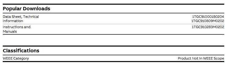
Display and operation: 32 character vacuum fluorescent display screen, 8-key keyboard (used for menu access, password verification, parameter settings, channel switching);
Configuration method: Controller parameters can be loaded through standard serial ports, supporting single channel/multi-channel display switching.
2. Input performance (sensors and signals)
(1) Input type and precision
Supporting multiple sensor inputs, the measurement range and accuracy of different types are shown in the table below:
Input type, specific specifications, accuracy (@ 25 ℃ environment)
Thermocouples support B/E/J/K/R/S/T types, including cold end compensation and reverse/short circuit detection; Type B has a range of 66-1760 ℃, Type K has a range of 268-1371 ℃ ± 1.0~4.0 ℃ (depending on the type, Type B has the lowest accuracy)
RTD is only supported by CLS204/CLS208, with 2/3 wire platinum resistance (100 Ω @ 0 ℃), divided into 2 ranges:
– RTD1:-100-275℃
– RTD2:-120-840℃ RTD1:±1.1℃; RTD2:±1.6℃
Linear signal supports 0-10mA/4-20mA DC current, 0-100mV/0-5V/0-10V/0-12V DC voltage (requires external scaling resistor)-
Pulse signal TTL level square wave, maximum frequency 2kHz-
Digital output: The number of outputs varies depending on the terminal board options – the 50 pin terminal board supports 34 digital outputs, while the 18 pin terminal board supports 10 control outputs; Each output can be configured as “switch time proportional control” or “distributed zero crossing (DZC) control”, with a maximum single current of 60mA (5V DC), and the onboard power supply can provide 350mA (5V DC);
Alarm output: Each channel is independently configured with “process alarm” and “deviation alarm”, supporting programmable dead zone, delay, and start suppression. The global alarm output can summarize the alarm status of all channels, and there is also a “watchdog output” to indicate that the controller is running normally.
4. Communication and Power Supply
Serial communication: Supports EIA/TIA-232 or EIA/TIA-485 (selectable via jumper), baud rates can be selected as 2400/9600/19200, protocol compatible with ANSI X3.28-1976 (D1, F1) and Allen Bradley PLC/2, Modbus ® RTU;
Power requirements: 15-24V DC (± 3V DC), maximum current 1A, current 300mA without load; optional 120/240V AC (50/60Hz) power adapter (output 15V) DC@1.2A , UL ® Class 2 certification).
5. Environmental adaptability
Working temperature: not clearly indicated (reference to general industrial equipment standards, estimated to be -10~55 ℃, subject to actual application);
Anti interference: Complies with industrial grade electromagnetic compatibility requirements (relying on the EMC testing standards corresponding to CE certification).
Optional accessories and software
1. Analog Conversion Module (DAC/SDC)
The CLS200 series has no onboard analog output and requires external modules to achieve analog signal conversion:
DAC module: converts the DZC output signals of 1-2 controllers into analog signals, and the output types can be configured on-site as 4-20mA DC, 0-5V DC, or 0-10V DC;
SDAC module (serial digital to analog converter): converts 1 controller output into high-precision analog voltage/current signals, suitable for scenarios such as process variable retransmission, open-loop control, motor speed control, etc., with CE, UL ®、 C-UL ® authentication.
2. Upper computer software (WATVIEW)
Optional Windows ®- Based HMI software, core functions include:
Simultaneously monitor/configure up to 32 CLS200 controllers;
Support parameter settings, custom recipe management, alarm monitoring, trend chart drawing, real-time data recording, and export log data to a spreadsheet;
Divided into “Run time” and “Developer” versions, the Developer version additionally supports custom interface design and has higher configuration efficiency than general HMI software.
Order information and attachments
1. Core ordering code rules
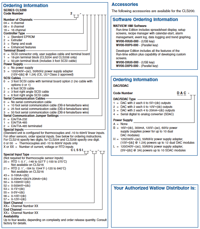
The CLS200 series order requires clear parameters such as “number of channels, controller type, terminal board, power supply, communication accessories, and special inputs”. The core code meanings are as follows:
Description of optional parameters for code snippets
Power adapter 0=none, 3=120/240V AC to 15V DC (1.2A)
Serial communication configuration communication cable (0=none, 1=10 feet DB-9 cable, etc.), communication protocol (0=232, 1=485, 2=485 terminal matching)
Special input 0/00=thermocouple only+(-10~60mV), X/XX=custom current/voltage/RTD input (input type and channel range need to be specified)
2. Other attachments
Software keys: WATVIEW runtime version (WV00-R0U0-000=USB key, WV00-R0P0-000=parallel key), development version (WV00-D0U0-000=USB key, etc.);
DAC/SDC power supply: B=120V AC to 16V DC (300mA, for 10 DACs), H=120/240V AC to 15V DC (1.2A, for 12 DACs), L=120/240V AC to 5V DC (3A, for 10 SDACs).
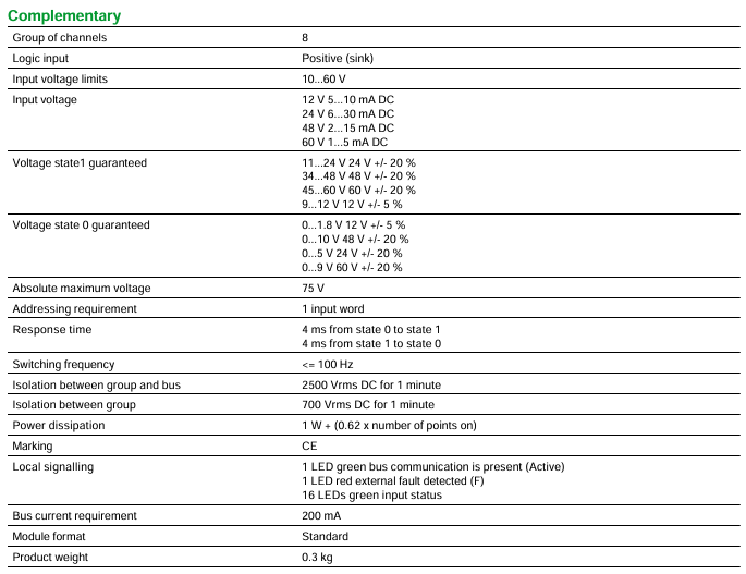
This module belongs to the DC discrete input module of Modicon Quantum automation platform, with the following core basic parameters:
Discrete input quantity: 16
Channel grouping: 8 channels per group
Input logic type: Positive (sink)
Address requirement: occupies 1 input word
Module Form: Standard Format
Product weight: 0.3kg
Certification mark: Compliant with CE certification
Electrical performance indicators
1. Input voltage and current
Input voltage range: 10-60V DC, with different current requirements for different voltages:
12V DC:5-10mA
24V DC:6-30mA
48V DC:2-15mA
60V DC:1-5mA
Voltage state threshold (guaranteed value):
State 1 (high level): 9-12V at 12V ± 5%, 11-24V at 24V ± 20%, 34-48V at 48V ± 20%, 45-60V at 60V ± 20%
State 0 (low level): 0-1.8V at 12V ± 5%, 0-5V at 24V ± 20%, 0-10V at 48V ± 20%, 0-9V at 60V ± 20%
Absolute maximum voltage: 75V DC
2. Response and switch performance
Response time: both state 0 → 1 and state 1 → 0 are 4ms
Switching frequency: ≤ 100Hz
3. Isolation and power consumption
Isolation performance: 2500Vrms DC (continuous for 1 minute) is isolated between channel groups and buses, and 700Vrms DC (continuous for 1 minute) is isolated between channel groups
Power consumption: 1W+(0.62 x activated points)
Bus current requirement: 200mA
Signal indication and anti-interference capability
1. Local signal indication (LED)
Green LED (Active): indicates normal bus communication
Red LED (F): Indicates detection of external fault
16 green LEDs: corresponding to the status of 16 input points (displaying whether the input is valid)
2. Anti interference standards
Electrostatic discharge resistance: Contact discharge 4kV, air discharge 8kV (compliant with IEC 801-2 standard)
Electromagnetic field resistance: 10V/m (frequency 80-2000MHz, in accordance with IEC 801-3 standard)
Environmental and Certification Requirements
1. Environmental adaptation range
Working environment temperature: 0-60 ° C
Storage environment temperature: -40-85 ° C
Relative humidity: 95% (without condensation)
Working altitude: ≤ 5000m
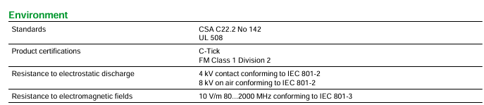
2. Product certification standards
Following standards: CSA C22.2 No 142, UL 508
Product certification: C-Tick certification, FM Class 1 Division 2 certification
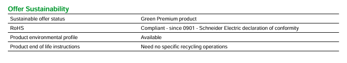
Sustainability and environmental attributes
Sustainable Supply Status: Belongs to “Green Premium Products” (Schneider Green Preferred Products)
RoHS Compliance: Compliant with RoHS standards since January 2009, with Schneider Electric Declaration of Conformity
Product environment file: obtainable
Scrap disposal: No special recycling operation is required, simplifying the subsequent environmental treatment process
Product type: 8-channel multi range differential analog input module, mainly used for the acquisition of analog signals (voltage, current) in industrial scenarios, suitable for automation control systems that require high-precision signal detection.
2. Discontinuation and replacement information
Key shutdown time: officially shut down on December 31, 2022, and terminate service on December 31, 2030.
Recommended alternative model: BMXAMI0810 (X80 series 8-channel high-speed isolated analog input module), please pay attention to the compatibility of the interface and parameters of the alternative module to ensure compatibility with the original system.
Core technical parameters
Input and Measurement Characteristics
Parameter category specific specifications
8 differential analog input channels
Input type supports 1… 5 V voltage signal, 4… 20 mA current signal
Resolution of 12 bits
Input impedance current signal: 250 Ω with ± 0.01% accuracy; Voltage signal:>20 M Ω
Absolute maximum input voltage: 50 V DC; Current: 25 mA
Measurement accuracy – absolute accuracy error: ± 0.05% of full scale, maximum not exceeding ± 0.1% of full scale
-Linear error: ± 0.04% of full scale
-Temperature drift: ± 0.0025%/° C of full scale, maximum not exceeding ± 0.005%/° C of full scale
Common mode rejection ratio>-72 dB at 60 Hz frequency
Filter characteristics: Single pole low-pass filter, 3 dB cut-off frequency 15 Hz (± 20% deviation)
Update time 5 ms
Isolation and Protection
Channel and bus isolation: 1000 V DC conventional isolation, can withstand 3000 V DC voltage for 60 seconds.
Channel isolation: 30 V DC to prevent signal interference between channels.
Fault detection: Supports wire breakage fault detection (4-20 mA signal) and undervoltage range detection (1-5 V signal), facilitating timely detection of signal abnormalities.
Electrical and Physical Specifications
Specification category details
Bus current requirement 240 mA
Power loss 2 W
Module format standard format, compatible with Modicon Quantum series rack
Net weight 0.3 kg
The address requirement occupies 9 input word address spaces, and corresponding address resources need to be reserved in the system configuration
Status indication and fault diagnosis
The module is equipped with multiple sets of LED indicator lights for real-time feedback of operating status and fault information. The specific functions are as follows:
Bus communication indicator light (green): On indicates normal bus communication (Active state), off or flashing indicates abnormal communication.
External fault indicator light (red): When lit, it indicates that the module has detected an external fault (such as signal over range, disconnection, etc.).
Channel enable indicator light (8 green lights): corresponding to 8 input channels, a single light indicates that the channel is enabled and working normally.
Channel fault indicator lights (8 red lights): corresponding to 8 input channels, when a single light is on, it indicates that the channel has a fault (such as signal abnormality, channel damage, etc.).
Environmental adaptability and compliance
Environmental Parameters
Environmental category specification requirements
Working environment temperature: 0… 60 ° C
Storage environment temperature -40… 85 ° C
Relative humidity of 95% (no condensation), suitable for high humidity industrial scenarios
Working altitude ≤ 5000 m, suitable for installation in high-altitude areas
Anti static discharge capability: Contact discharge 4 kV, air discharge 8 kV (compliant with IEC 801-2 standard)
Anti electromagnetic interference at frequencies of 80-1000 MHz, with a field strength of 10 V/m (in accordance with IEC 801-3 standard)
Certification and Compliance
Compliance category specific certification/standards
UL 508 safety certification, CSA C22.2 No 142, FM Class 1 Division 2, cUL certification, meeting industrial safety standards
Environmental Compliance – EU RoHS: Proactive Compliance (If the product exceeds the EU RoHS legal scope, provide a RoHS declaration)
-Mercury free design, in compliance with environmental requirements
-China RoHS: Provide RoHS Declaration
-Provide product environmental records, recycling records, and scrap information
-EU WEEE Directive: Specific waste collection procedures must be followed for disposal, and mixing with ordinary household waste is prohibited
The label bears the CE mark and complies with relevant electromagnetic compatibility and safety standards of the European Union
Packaging and Quality Assurance
Packing Specification
Provide two packaging specifications to meet different procurement and transportation needs:
Packaging type Unit type Packaging quantity Weight dimensions (length x width x height)
Packaging 1 PCE (unit) not clearly labeled 450 g 31 cm × 16.5 cm × 4.8 cm
Package 2 S03 (box) not clearly labeled 3.6 kg 40 cm × 30 cm × 30 cm
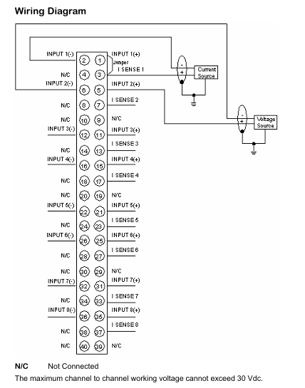
Connection and installation
Key Instructions for Wiring Diagram
Channel wiring: Each input channel contains positive and negative poles (such as INPUT 1 (+), INPUT 1 (-)), and some pins are labeled as “N/C” (Not Connected), indicating that no connection is required to avoid module damage caused by misconnection.
Sense pins: Set the SENSE2-SENSE8 pins for signal detection and compensation, and connect them correctly according to the actual signal type (voltage/current) to ensure measurement accuracy.
Voltage limit between channels: The working voltage between channels must not exceed 30 V DC to prevent interference or damage caused by high voltage between channels.
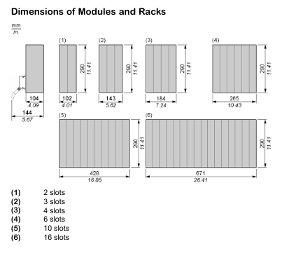
Rack Installation
The module is compatible with Modicon Quantum series standard racks and supports various rack specifications such as 2 slots, 3 slots, 4 slots, 6 slots, 10 slots, 16 slots, etc. During installation, it is necessary to ensure good contact between the module and the rack, secure it firmly, and avoid poor contact caused by vibration.
The ControlLogix series controllers are divided into two major series, 5570 and 5560, as well as extreme environment type (- XT suffix) and Armor protection type (- EROM suffix). The core differences are as follows:
Features ControlLogix 5570 ControlLogix 5560
Power Supply and Memory Backup Energy Storage Module (ESM) Lithium Battery (1756-BA1/BA2/BATM)
Built in communication port USB 2.0 (temporary programming only, cable length ≤ 3m, no hub) RS-232 serial port
Extreme environment type (- XT): such as 1756-L73XT/L63XT, supports working temperatures of -25~+70 ° C, and other functions are consistent with the corresponding basic model.
Armor protective type (- ROM): such as 1756-L72EROM/L73EROM, integrated with 1756-L7x controller and 2 EtherNet/IP DLR communication modules, IP67 protection level, suitable for machine installation, ESM non removable.
Installation and hardware configuration
1. Installation environment requirements
Environmental conditions: Pollution level 2 industrial environment, overvoltage category II, altitude ≤ 2000m, no derating requirements; Storage temperature -40~+80 ° C, working temperature for conventional type 0~+60 ° C, extreme type -25~+70 ° C.
Shell requirements: It needs to be installed in a shell that complies with NEMA 250 or IEC 60529 standards, with a flame retardant rating of 5VA (non-metallic shells need to be certified), and can only be opened with tools inside. The explosion-proof environment needs to additionally comply with ATEX/IECEx requirements (such as Zone 2 environment requiring an IP54 or above shell).
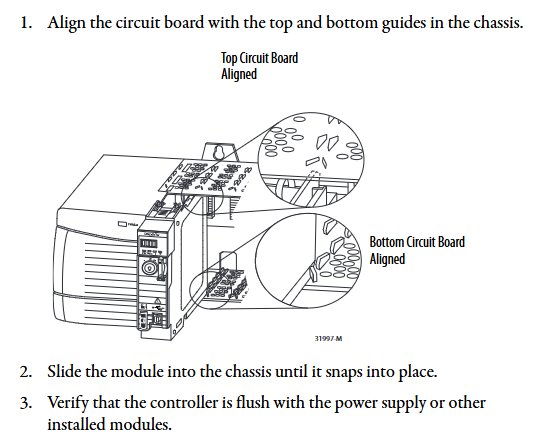
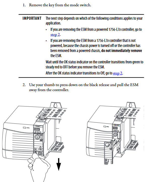
2. Core hardware installation steps
(1) Key installation of ControlLogix 5570
**Chassis and power supply pre installation * *: Chassis and power supply need to be installed according to the manuals “1756-IN621 (Chassis)” and “1756-IN619 (Power Supply)” first.
Controller insertion: Align the upper and lower rails of the chassis, slide in to the buckle lock, and ensure that it is flush with adjacent modules; Attention should be paid to the risk of electric arc in explosion-proof environment during live plugging and unplugging. It is recommended to perform power-off operation.
ESM installation: Align with the tongue and grain slot and push it into the buckle for fixation. After installation, start charging (up to 2 minutes, the status screen displays “CHRG”). Do not turn off the power before charging is complete, otherwise the program may be lost.
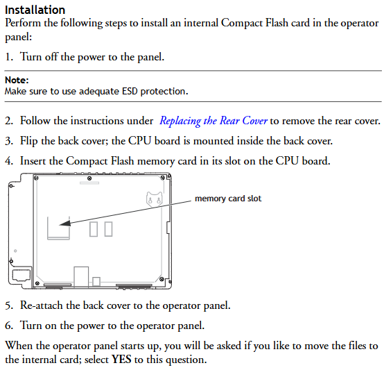
SD card operation: Open the SD card card, insert the 1784-SD1/SD2 card (recommended original card to avoid data damage), and press it until the card buckle locks; Before removal, it is necessary to confirm that the SD indicator light is off and that the explosion-proof environment requires power-off operation.
(2) Key installation of ControlLogix 5560
Battery installation: Series A uses 1756-BA1/BATM, Series B uses 1756-BA2, connect the positive and negative poles (red+black -), write the replacement date and paste it on the inside of the cabinet door.
CompactFlash card operation: Series A needs to lift the locking clip to insert, Series B needs to push open the buckle and insert, and before removing, confirm that the OK indicator light is green.
3. Hardware security specifications
Static protection: Before operation, touch grounded objects to discharge electricity, wear a grounding wristband, avoid touching connector pins and internal circuits, and use anti-static workstation storage devices.
Explosion proof requirements: In Class I Zone 2 (Groups A-D) environments, equipment/components can only be plugged in and out after power failure or confirmation of non hazardous areas; It is prohibited to replace non certified components, and batteries must be replaced in non hazardous areas.
Software configuration and firmware upgrade
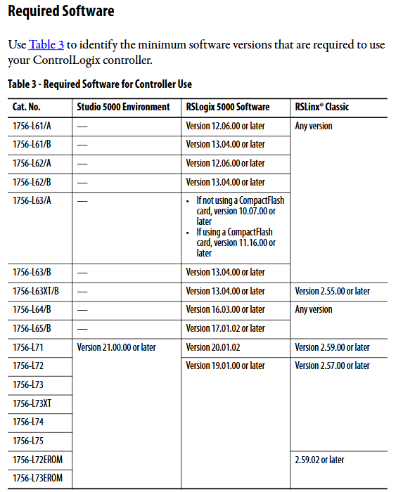
1. Essential software and version requirements
Different controller models need to be matched with specific software versions, and the core requirements are as follows:
Controller model Studio 5000 environment minimum version RSLogix 5000 minimum version RSLinx Classic minimum version
1756-L71/L72/L73 and other V21.00.00 V20.01.02 V2.59.00
1756-L61/A – V12.06.00 any version
1756-L63XT/B – V13.04.00 V2.55.00
2. Firmware upgrade method
Supports two methods: ControlFLASH software and AutoFlash (built-in in Logix Designer). The steps are as follows:
(1) ControlFLASH upgrade
Connect the controller (USB/Ethernet), start ControlFLASH, select the controller model and network driver.
Select the target firmware version (download the matching version from the official website to avoid file corruption), click “Finish” to start the upgrade, and do not turn off the power during the process.
After the upgrade is completed, the controller automatically restarts and the confirmation status screen displays the new firmware version (such as “Rev 30.011”).
(2) AutoFlash upgrade
Create a project in Logix Designer, click on “Who Active” to find the target controller, and select “Update Firmware”.
Select the firmware file path and version, confirm that the controller is in “Remote Program” mode and there are no uncleared faults, and click “Update”.
During the upgrade process, the progress is displayed (5570 points for “update count/block count”, 5560 only displays “block count”), and the firmware version is verified after completion.
3. Memory and storage configuration
5570 series: SD cards are used to store project and fault logs, supporting three modes: “power on load”, “load when memory is damaged”, and “user triggered load”. Locking the SD card can prevent firmware from being overwritten.
5560 series: The CompactFlash card needs to be configured with the “store/load” parameter in Logix Designer, supporting program backup and recovery. When replacing the battery, ensure that there is a backup in the card to prevent data loss.
Communication network configuration
1. Supported communication protocols and modules
The controller supports multiple types of industrial networks and requires corresponding communication modules. The core configuration is as follows:
Network type, communication module model, core function, maximum number of connections/bandwidth limit
EtherNet/IP 1756-ENBT/EN2TR/EN3TR supports production and consumption tags, I/O control, and HMI communication. 1756-EN3TR supports 256 movements in 128 axes (EN2T/EN2TR); 128 (ENBT)
DeviceNet 1756-DNB connects distributed I/O and drivers, supports scanning list configuration with 124 DINT input/123 DINT output
Data Highway Plus (DH+) 1756-DHRIO/DHRIOXT connects PLC-5/SLC controllers, supporting 32 sites at 57.6/115.2/230.4 kbps rates
HART 1756-IF8H/OF8H analog I/O+digital signal superposition, supports direct connection to HART transmitter for device diagnosis
2. Key steps for communication configuration
(1) EtherNet/IP configuration
Add modules such as 1756-EN2T in the “I/O Configuration” of Logix Designer and set the IP address (supporting BOOTP/DHCP allocation).
Configure “Production/Consumption Tags”: Production tags need to specify the number of consumers, while consumption tags need to match the production tag data type and RPI (Request Packet Interval).
Remote I/O configuration: Reduce the number of connections through “rack optimization connections”, and a single connection can cover the entire remote rack I/O.
(2) Serial Communication (5560 Series)
Connect the 1756-CP3 serial port cable, configure the “RS-232 DF1 device driver” in RSLinx, and select the “Logix 5550/CompactLogix” device type.
The Logix 5000 control program consists of a three-level structure of “task program routine”, with the following core rules:
Tasks (up to 32):
Continuous task (1): lowest priority, utilizing idle CPU time for cyclic execution.
Periodic task: Execute at set intervals (0.1~2000000ms), priority 1~15 (highest 1).
Event task: triggered by triggering conditions (such as I/O status changes, consumption tag triggers) for execution.
Program (up to 1000 per task, V24+): Contains local tags, parameters, main routines, fault routines, supports “scheduled execution” (executed in sequence) and “unplanned execution” (only verified and not running).
Routine: executable code written in a single programming language, supporting ladder diagrams (LD), function block diagrams (FBD), structured text (ST), and sequential function diagrams (SFC).
2. Core programming functions
(1) Production/Consumption Tags (Interlock Data)
Production label: One controller releases data, and multiple controllers (up to 32) consume it simultaneously. It must be on the same network (not bridged across networks), and the data type and array dimension must be consistent.
Connection calculation: The production label occupies “number of consumers+1” controller connection, the consumption label occupies 1 connection, and the communication module occupies an additional 1 connection.
(2) MSG instruction (message communication)
Supports types such as “CIP Data Table Read/Write”, “PLC-5/SLC Communication”, “General CIP”, etc. It can cache connections (optimize speed during repeated execution, up to 32 cache connections) or non cache connections (release connections after execution).
Block Transfer requires the configuration of a “request/response” data area, which is suitable for high-speed counters, frequency converters, and other devices.
(3) Motion control
Supports EtherNet/IP integrated motion (Kinetix 350/5500/6500 drivers), Sercos interface (1756-M03SE/M08SE module), and analog interface (1756-HYD02 module).
Core instructions: MSO (servo enable), MAH (axis return to zero), MAJ (axis jog), MAM (axis positioning), need to create “axis labels” and configure parameters such as speed and acceleration.
3. PhaseManager tool (device phase control)
Function: Divide device operation stages (such as Resetting/Running/Holding) according to the S88/Pack ML state model, simplify process programming, support “action state” (executing operations) and “waiting state” (waiting when conditions are met).
Core instructions: PSC (Stage Completion Signal), PCMD (Stage State Switching), PFL (Stage Fault Signal), which need to be enabled in Logix Designer V21+and support multitasking scheduling.
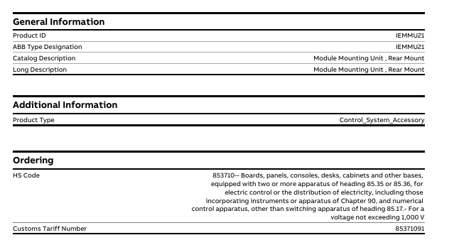
Product description (including brief/long description): Module Mounting Unit, Rear Mount (rear mounted module mounting unit)
Product Type: Control_System_Sccessory (Control System Accessories)
Order related:
HS code: 853710 (boards, panels, consoles, tables, cabinets, and other bases equipped with two or more 85.35 or 85.36 devices, used for electrical control or power distribution, including instruments/equipment and CNC equipment in Chapter 90, excluding 85.17 switchgear, voltage not exceeding 1000V, other categories)
Number of batteries: 0 (without built-in batteries)
SCIP Information: Identification Number: 7dc615b7-fde4-47e9-96c4-2d678387c8df, Associated Region: India (IN)
Product classification attribution
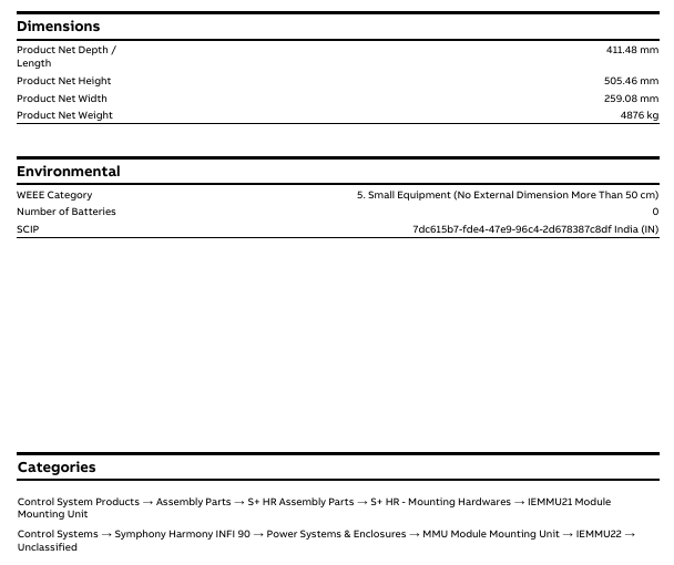
IEMMU21, as a control system attachment, belongs to the following product classification system, covering different control systems and component categories:
Control System Products → Assembly Components → S+HR Assembly Components → S+HR – Hardware Installation → IEMMU21 Module Installation Unit
Control System → Symphony Harmony INFI 90 Control System → Power System and Housing → MMU Module Installation Unit → IEMMU22 → Unclassified
First, the importance of industrial equipment installation
In modern industrial production, various equipment and machines are widely used in various fields, such as manufacturing, energy industry, chemical industry and so on. The installation of industrial equipment is directly related to production efficiency and product quality. Proper installation and commissioning of good equipment can ensure the stable operation of the production line, improve production efficiency and product quality, reduce maintenance costs, and ensure the safety of employees.
Second, the steps of industrial equipment installation
1. Preparation: Before the installation of industrial equipment, it is necessary to carry out adequate preparation work. This includes the tools and equipment required for installation, cleaning and preparation of the installation site, and making installation plans and schedules.
2. Determine the installation position: Determine the installation position of the equipment according to the requirements of the equipment and the layout of the production line. When determining the location, the weight and size of the equipment need to be considered, as well as the coordination of the equipment with the surrounding environment.
3. Install the device: Assemble and install the device according to the installation instructions. Ensure that the device is securely and accurately connected, while protecting the appearance and internal components of the device.
4. Connect power supplies and pipelines: For devices that require power supplies and power supplies, properly connect power supplies and pipelines. The connection of power supply and pipeline should comply with safety standards to avoid hazards such as electric shock and leakage.
5. Commissioning the device: After the installation is complete, you need to commission the device to ensure that the device can run properly. It includes checking the functions and performance of the equipment, adjusting the parameters and Settings of the equipment, and carrying out the necessary tests and inspections.
6. Training operators: After the installation of the equipment, it is necessary to train the operators to understand the operation methods and precautions of the equipment, and improve the operation skills and safety awareness of the employees.
1. Safety first: When installing industrial equipment, safety is the most important consideration. You must operate in strict accordance with safety regulations and wear necessary protective equipment to ensure the safety of the workplace.
2. Strictly follow the equipment instructions: Industrial equipment usually comes with detailed installation instructions, you must carefully read and understand the contents of the instructions, and install the operation in accordance with the requirements of the instructions.
3. Pay attention to the assembly sequence: When installing the device, follow the correct assembly sequence to ensure that all components of the device are assembled correctly to avoid equipment failures or safety accidents caused by incorrect assembly sequence.
Product core positioning and application scenarios
1. Product positioning
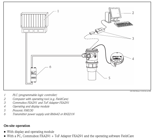
Prosonic T FMU30 is a compact ultrasonic level measurement transmitter that uses non-contact measurement method and is suitable for continuous level monitoring of liquids, paste materials, and coarse granular materials. It supports 4-20mA signal output for system integration.
2. Scope of application
Measurement objects: liquids (such as clean water, sewage, and oil), paste like materials (such as mud and paint), and coarse granular materials (such as gravel and coal).
Measurement range (varies depending on sensor size):
1.5-inch sensor: maximum 5m (16ft) in liquid, maximum 2m (6.6ft) in bulk material, blind spot 0.25m (0.8ft).
2-inch sensor: maximum 8m (26ft) in liquid, maximum 3.5m (11ft) in bulk material, blind spot 0.35m (1.1ft).
Measurement Principles and Core Technologies
1. Measurement principle (time-of-flight method)
The sensor emits ultrasonic pulses onto the surface of the material, which are reflected and received by the sensor.
The device measures the time difference t between pulse emission and reception, combined with the sound velocity c, and calculates the distance D from the sensor diaphragm to the material surface using the formula D=c ⋅ t/2.
Based on the user’s preset empty tank distance E, calculate the actual liquid level L using the formula L=E-D.
Built in NTC temperature sensor can automatically compensate for the impact of temperature changes on sound velocity, ensuring measurement accuracy.
2. Key functions
Interference echo suppression: Filter the interference echoes generated by container edges, welds, internal equipment, etc., to avoid misjudging the liquid level.
Linearization function: Supports up to 32 linearization points, can convert measurement values into length, volume, or flow units (applicable for open channel/weir flow calculation), and pre stores a linearization table for horizontal cylindrical tank volume calculation.
Signal output: 4-20mA analog signal, customizable output during alarm (compliant with NAMUR NE43 standard), output damping can be freely set within 0-255s.
Technical parameters and performance indicators
1. Basic electrical parameters
Parameter specifications
Supply voltage 14-35V DC
Power consumption 51mW-800mW
Current consumption 3.6-22mA
The cable interface has a cross-sectional area of 0.25-2.5mm ² (24-14 AWG), and the cable entry is G/2 “or 1/2” NPT. The recommended cable diameter is 6-10mm
The protective circuit is equipped with reverse polarity protection, radio frequency interference (RFI) protection, and overvoltage spike protection
2. Measurement performance
Resolution: 1mm (0.04in).
Maximum measurement error: ± 0.2% of the sensor’s maximum range (in accordance with EN 61298-2 standard, under reference operating conditions).
Typical measurement error: better than ± 3mm (± 0.12in) or 0.2% of the measured distance (whichever is greater).
Response time: Minimum of 2 seconds (depending on parameter settings).
Pulse frequency: Maximum 0.5Hz (varies depending on device type and parameters).
3. Environmental and process adaptability
Category specifications
Operating temperature range: -20 ° C to+60 ° C (-4 ° F to+140 ° F, it is recommended to install a rain cover when using outdoors); Storage: -40 ° C to+80 ° C (-40 ° F to+176 ° F)
Protection level: IP66/IP68 when the shell is closed (24 hours at 1.83m underwater); IP20 when the shell is opened
Vibration resistance meets DIN EN 60068-2-64 standard, 20-2000Hz, 1 (m/s ²)/Hz, 3 × 100min
Electromagnetic compatibility (EMC) complies with EN 61326 standard, industrial environment anti-interference level, EMC impact<1% of full scale
Process temperature -20 ° C to+60 ° C (-4 ° F to+140 ° F)
Process pressure 0.7-3bar abs. (10.15-43.5psi abs.)
Mechanical structure and installation requirements
1. Mechanical specifications
Size and weight:
1.5-inch sensor: weighs approximately 0.75kg (1.65lbs), with process connections of G 1.5 “or NPT 1.5”.
2-inch sensor: weighs approximately 0.8kg (1.76lbs), with process connections of G 2 “or NPT 2”.
Material: The outer shell is PBT-FR (flame retardant polybutylene terephthalate), the sensor material contact part is PP (polypropylene), and the seal is EPDM (ethylene propylene diene monomer rubber), ensuring chemical compatibility and durability.
Installation specifications
(1) General requirements
Avoid installing in the center of the tank. It is recommended that the distance between the sensor and the tank wall be 1/6 of the tank diameter to prevent reflection interference from the tank wall.
To avoid the measurement path passing through the feeding curtain, the sensor membrane should be perpendicular to the material surface in the application of bulk materials (to avoid the influence of conical accumulation).
Equipment inside the tank (such as limit switches and temperature sensors) should avoid ultrasonic emission angles (11 °), and two ultrasonic measuring devices cannot be installed in the same tank to prevent signal interference.
(2) Special scenario installation
Narrow axis installation: PE or PVC waveguide pipes with a diameter of ≥ 100mm should be used, and regular cleaning should be carried out to avoid contamination affecting the measurement.
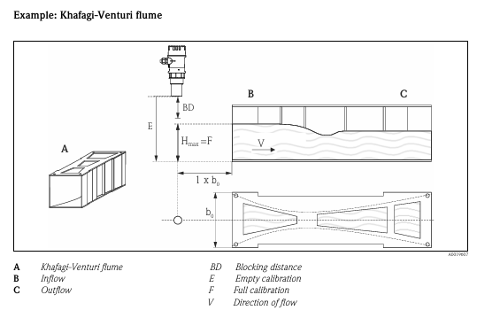
Flow measurement (open channel/weir): Installed on the inflow side, near the maximum water level H max (with a blind zone reserved), the sensor diaphragm is parallel to the water surface and centrally installed above the channel/weir.
Nozzle installation: If the blind spot requirements cannot be met, a smooth and edgeless nozzle should be used, with a nozzle diameter that matches the maximum length (such as a DN50 nozzle with a maximum length of 80mm and a DN100 nozzle with a maximum length of 300mm).
Operation mode and functional configuration
1. Local operation
Display and buttons: 4-line pure text LCD display screen (supporting 7 languages: German, English, Spanish, French, Italian, Japanese, Dutch), equipped with navigation and confirmation keys, allowing for intuitive viewing of measured values, envelope curves (for fault diagnosis), and alarm information.
Hardware lock: After long pressing the lock button, you need to enter the unlock parameter (100) to operate again to prevent accidental touch.
2. Remote operation
Connect to a PC via Commubox FXA291 (communication box) and ToF Adapter FXA291 (time-of-flight adapter), and use FieldCare software (Endress+Hauser’s FDT asset management tool) to achieve remote configuration. The supported functions include envelope curve signal analysis and linearization table editing (import/export).
Equipment data upload/download, measurement point document recording.
Compatible with Ethernet, HART, PROFIBUS PA and other protocols, supporting third-party FDT standard devices.
Certification qualifications and compliance
Certification type specific standards/certification content
CE certification meets the requirements of EU directives, passes relevant tests, and bears the CE mark
Explosion-proof certification ATEX II 1/2G Ex ia IIC T5 Ga/Gb、IECEx Ex ia IIC T5 Ga/Gb、CSA C/US Class I Div.1 Gr.A-D、NEPSI Zone 0/1 Ex ia IIC T5 Ga/Gb
Environmental and safety standards comply with DIN EN 60529 (protection level), EN 61326 (EMC), NAMUR NE43 (alarm signal), EN 61298-2 (measurement accuracy), etc
Ordering Information and Accessories
1. Ordering Code Rules
It is necessary to specify a combination of 7 dimensions of parameters to generate a complete order number, with key parameters including:
010 (certification type): such as AA (non hazardous area), BB (ATEX explosion-proof), IB (CSA explosion-proof).
020 (display and operation): such as G (no local display), H (with envelope curve display+button).
040 (sensor specifications): such as AA (1.5-inch sensor), AB (2-inch sensor).
050 (process connection): such as GGF (G 1.5 “thread, PP material), RHF (NPT 2” thread, PP material).
2. Standard accessories and optional accessories
Standard supply scope: transmitter body, brief instruction manual (KA01054F), CD-ROM document, explosion-proof version including safety instructions, PC material for nuts (GGF/GHF version), EPDM sealing ring.
Optional accessories: Installation bracket (316Ti or galvanized steel material), threaded flange (PP/PVDF/316L material, suitable for different DN specifications), cantilever bracket+installation frame/wall frame, rain cover (PBT material, suitable for -50 ° C to+150 ° C), Commubox FXA291 and ToF Adapter FXA291.
Maintenance and Safety Tips
Daily maintenance: Regularly clean the sensor membrane to avoid contamination affecting ultrasonic transmission; During narrow axis installation, it is necessary to regularly clean the waveguide.
Safety precautions: Explosion proof versions must strictly follow the corresponding safety instructions (such as XA01054F, XA01080F), and installation and maintenance must be carried out by professional personnel; Avoid contact between the sensor and high vapor pressure media (such as ethanol and acetone), and consult the manufacturer for compatibility if necessary.
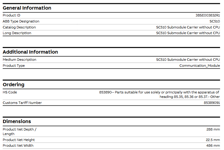
-Product description (including brief/long description): SC510 without CPU submodule carrier
Product Type Communication-Module
Order related – HS code: 853890 (applicable to specialized or major parts of equipment under items 85.35, 85.36, or 85.37, other categories)
-Customs tariff number: 85389091
Physical specifications
Dimensions: Product net depth/length 288mm, net height 22.5mm, net width 486mm.
Weight: The net weight of the product is 0.67kg.
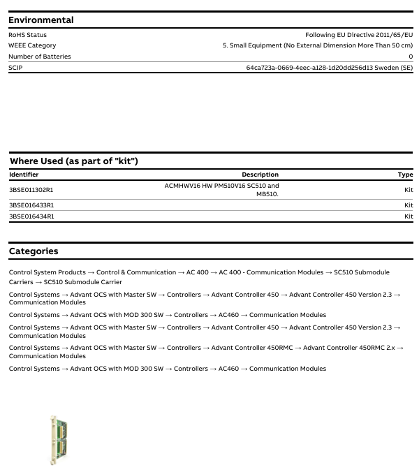
Environment and Compliance
Compliance category and specific requirements
RoHS status, compliant with EU Directive 2011/65/EU
WEEE category, category 5 (small equipment with no external dimensions exceeding 50cm)
Number of batteries, 0 (without built-in batteries)
SCIP information, identification number: 64ca723a-0669-4eec-a128-1d20dd256d13, associated region: Sweden (SE)
Suite application scenarios (as a component of the “suite”)
SC510 can be used as a component of the following kit, with specific kit information as follows:
Kit identifier, kit description, type
3BSE011302R1, ACMHWV16 hardware PM510V16, SC510 and MB510, Kit
3BSE016433R1、 Not labeled with specific description, Kit
3BSE016434R1、 Not labeled with specific description, Kit
Product classification attribution
SC510 belongs to the communication module, and its specific product classification system is as follows, covering different control systems and versions:
Control system products → Control and communication → AC 400 → AC 400- Communication module → SC510 submodule carrier → SC510 submodule carrier
Control System → Advant OCS with Master Software → Controller → Advant Controller 450 → Advant Controller 450 Version 2.3 → Communication Module
Control system → Advant OCS with MOD 300 software → Controller → AC460 → Communication module
Control System → Advant OCS with Master Software → Controller → Advant Controller 450RMC → Advant Controller 450RMC 2. x → Communication Module
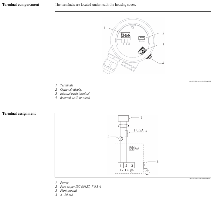
The equipment is only suitable for Class I Zone 2 (Groups A, B, C, D) or non hazardous locations. The combination of equipment in the system must be inspected by the local competent department.
The maximum ambient temperature for horizontal installation is 40 ° C, and for vertical installation it is 50 ° C.
There is an explosion risk warning, such as not disconnecting the equipment before power outage, component replacement may affect applicability, only UL and cUL certified expansion units are allowed to be connected (currently there are no relevant evaluated units), batteries need to be replaced in non hazardous areas, and AWG 28-12 cables need to be used to connect the power supply, with a minimum tightening torque of 0.5 Nm, and can only be used in 4X shell flat rooms.
General Safety Rules
It is necessary to carefully read the safety precautions, inspect for transportation damage, and promptly notify the supplier. The use of equipment in high explosive risk environments is prohibited.
Suppliers are not responsible for modifying, altering, or reassembling equipment and may only use components and accessories that meet the supplier’s specifications.
Before installation, use, or maintenance, it is necessary to read the relevant instructions to prevent liquids, metal debris, etc. from entering the equipment and causing fires or electric shocks, and only qualified personnel are allowed to operate.
The storage temperature of the device must meet the requirements, otherwise it may cause the LCD display liquid to solidify or denature. If the display liquid comes into contact with the skin or eyes, it should be handled in a specific way.
The illustrations in the manual are for illustration purposes only, and the supplier is not responsible for the actual use based on the illustrations, nor does they guarantee that the equipment is suitable for specific applications or assume responsibility for product design, installation, or operation.
Safety during installation
The operation panel should be fixedly installed on a flat surface without high explosion risk, strong magnetic field, direct sunlight, or drastic temperature changes, and installed and grounded according to the installation instructions, and only by qualified personnel.
High voltage cables, signal lines, and power lines need to be separated, and the voltage and polarity should be confirmed to be correct before connecting the power supply. Peripheral equipment should be adapted to the application scenario and location.
Safety during use
Keep the control panel clean. Emergency stop and other safety functions cannot be controlled by the control panel. Avoid using excessive force or sharp objects when operating buttons or touch screens.
Service and Maintenance of Security
Only qualified personnel are allowed to carry out repairs, following the agreed warranty terms. Before cleaning or maintenance, the power must be disconnected, and the display panel and front cover must be cleaned with a soft cloth and mild cleaning agent. The battery must be replaced according to the supplier’s recommended model to avoid accidental replacement and explosion.
Disassembly and scrapping safety
The operation panel or its components need to be recycled according to local regulations. Components such as lithium batteries, electrolytic capacitors, and displays contain substances that may harm health and the environment.
Product Introduction
Product Model Classification and Parameters
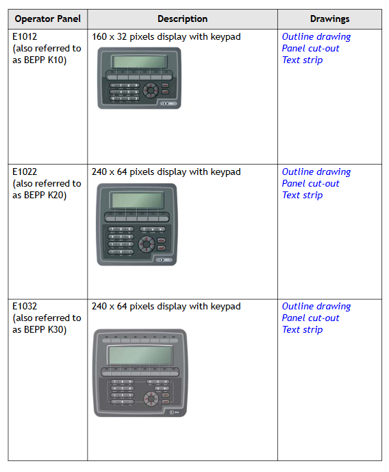
The E1000 series operation panel is divided into keyboard operation type and touch screen operation type. The specific models, descriptions, and corresponding drawings are as follows:
Type and Model Description Drawing
Keyboard operated E1012 (BEPP K10) 160 × 32 pixel display screen with keyboard outline, panel cutout, and text bar
E1022 (BEPP K20) 240 × 64 pixel display screen with keyboard outline, panel cutout, and text bar
E1032 (BEPP K30) 240 × 64 pixel display screen with keyboard outline, panel cutout, and text bar
E1060/E1062 (BEPP K60) 5.7-inch display screen with keyboard outline, panel cutout, and text bar
E1070 (BEPP 64K) 6.5-inch display screen with keyboard outline, panel cutout, and text bar
E1100 (BEPP 104K) 10.4-inch display screen with keyboard outline, panel cutout, and text bar
Touch screen operation type E1041/E1043 (BEPP T40) 3.5-inch touch screen display outline and panel cut diagram
E1151 (BEPP 150T) 15 inch touchscreen display outline and panel cutout diagram
Maintenance Requirements
Before maintenance, it is necessary to carefully read the instructions. Only qualified personnel are allowed to operate. Follow the warranty and license agreement. Equipment damage caused by personnel will void the warranty.
Before cleaning or maintenance, disconnect the power supply and use a soft cloth and mild cleaning agent (such as water, isopropanol, or hexane) to clean the display panel and front cover. The battery should be replaced according to the recommended model to prevent explosion. All repaired parts are covered by a 6-month warranty.
Maintenance personnel can perform operations such as back cover replacement, battery replacement, backlight replacement, and complete front cover replacement.
Service and Maintenance Regulations
Only authorized companies are allowed to provide services and repairs. Unauthorized company operations will result in the warranty being invalidated. If training is required, please contact the supplier.
All maintenance must be carried out within the temperature range of 15-30 ° C. The warranty for equipment damage caused by personnel is invalid, and the customer contract takes precedence over the document information.
Disassembly and scrapping requirements
The operation panel or its components must be recycled according to local regulations. Lithium batteries, electrolytic capacitors, displays, and other materials that may pose a risk to health and the environment.
Hardware related content
Hardware Overview
Before the operation panel is launched, it needs to be tested by an independent organization. For example, the E1000 series needs to pass CE, UL and other standard tests. Manufacturers have quality and environmental policy requirements for suppliers and subcontractors.
Hardware Testing
Manufacturers conduct comprehensive hardware testing before obtaining approval for the control panel, with some testing performed by external testing companies such as the Swedish National Testing and Research Institute. All products must pass the testing before leaving the factory.
Hardware specifications
Keyboard operation panel
There are differences in the technical parameters of different types of keyboard operation panels, and the following are the main model parameters:
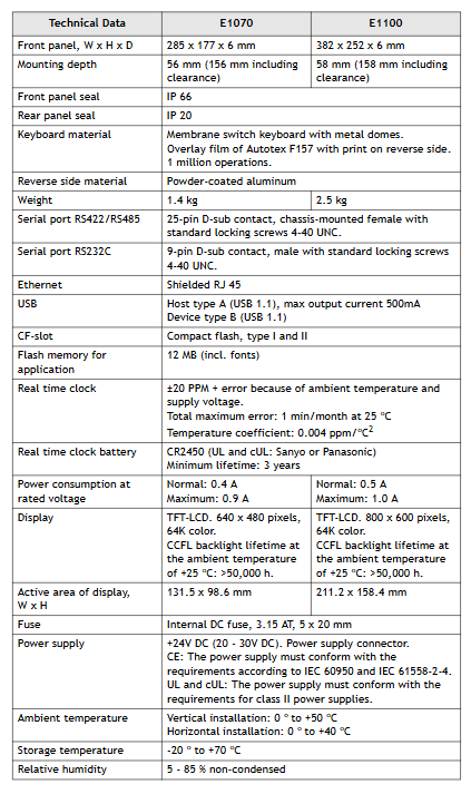
Parameter E1012 E1022 E1032 E1060 (hardware version 07900 and above) E1062 E1070 E1100
Front panel dimensions (W x H x D) 155 x 114 x 6mm 155 x 155 x 6mm 202 x 187 x 6mm 275 x 168 x 6mm -285 x 177 x 6mm 382 x 252 x 6mm
Installation depth 46.4mm (including gap 146.4mm) -57mm (including gap 157mm) -57mm (including gap 157mm) -56mm (including gap 156mm) 58mm (including gap 158mm)
Front panel protection level IP 66- IP 66 IP 66- IP 66-
Rear panel protection level IP 20- IP 20 IP 20- IP 20-
Keyboard material: Thin film switch keyboard with metal shrapnel, Autotex F207 laminated (back printed), operable up to 1 million times – Thin film switch keyboard with metal shrapnel, Autotex F157 laminated (back printed), operable up to 1 million times – Thin film switch keyboard with metal shrapnel, Autotex F157 laminated (back printed), operable up to 1 million times – Thin film switch keyboard with metal shrapnel, Autotex F157 laminated (back printed), operable up to 1 million times-
Back Material Powder Coated Aluminum Powder Coated Aluminum Powder Coated Aluminum Powder Coated Aluminum Powder Coated Aluminum-
Weight 0.45kg 0.55kg 0.95kg 1.2kg-1.4kg 2.5kg
RS232C serial port 9-pin D-sub male, with 4-40 UNC standard locking screw -9-pin D-sub male, with 4-40 UNC standard locking screw -9-pin D-sub male, with 4-40 UNC standard locking screw -9-pin D-sub male, with 4-40 UNC standard locking screw-
RS422/RS485 serial port -25 pin D-sub female head (chassis mounted) with 4-40 UNC standard locking screw, 25 pin D-sub female head (chassis mounted) with 4-40 UNC standard locking screw -25 pin D-sub female head (chassis mounted), with 4-40 UNC standard locking screw-
Ethernet is connected through the Ethernet expansion module installed on the back – shielded RJ45 shielded RJ45 shielded RJ45 shielded RJ45-
USB – A-type host (USB 1.1), maximum output current 500mA A-type host (USB 1.1), maximum output current 500mA – A-type host (USB 1.1500mA), B-type device (USB 1.1)-
Real time clock ± 20 PPM, affected by ambient temperature and power supply voltage, maximum monthly error of 1 minute at 25 ° C, temperature coefficient 0.004ppm/° C ² – same left same left – same left-
Real time clock battery MS614S (UL and cUL: SII Micro Parts LTD) – CR2450 (UL and cUL: Sanyo or Panasonic), minimum lifespan of 3 years CR2450 (UL and cUL: Sanyo or Panasonic), minimum lifespan of 3 years – CR2450 (UL and cUL: Sanyo or Panasonic), minimum lifespan of 3 years-
Normal power consumption at rated voltage: 0.1A, maximum 0.3A – normal 0.15A, maximum 0.35A – normal 0.2A, maximum 0.4A – normal 0.3A, maximum 0.5A – normal 0.4A, maximum 0.9A – normal 0.5A, maximum 1.0A
Display screen FSTN-LCD, 160 × 32 pixels, monochrome transmission negative display, LED backlight (lifespan>47000h at 25 ° C) FSTN-LCD, 240 × 64 pixels, monochrome transmission negative display, LED backlight (lifespan>47000h at 25 ° C) FSTN-LCD, 240 × 64 pixels, monochrome semi transparent and semi reflective, LED backlight (lifespan>35000h at 25 ° C) TFT-LCD, 320 × 240 pixels, 64K colors, LED backlight (lifespan>20000h at 25 ° C) TFT-LCD, 320 × 240 pixels, 16 grayscale TFT-LCD, 640 × 480 pixels, 64K colors, CCFL backlight (lifespan>50000h at 25 ° C) h) TFT-LCD, 800 × 600 pixels, 64K colors, CCFL backlight (lifespan>50000h at 25 ° C)
Effective area of display screen (W × H) 89.6 × 17.9mm 90.2 × 24.0mm 127.0 × 33.8mm 115.2 × 86.4mm -131.5 × 98.6mm 211.2 × 158.4mm
Internal DC fuse, 1.0AT, 5 × 20mm – Internal DC fuse, 2.0AT, 5 × 20mm – Internal DC fuse, 2.0AT, 5 × 20mm – Internal DC fuse, 3.15AT, 5 × 20mm-
Power supply+24V DC (20-30V DC), power connector; CE: Must comply with IEC 60950 and IEC 61558-2-4; UL and cUL: Must comply with Class II power requirements – Same Left Same Left Same Left-
Environmental temperature 0-50 ° C – vertical 0-50 ° C, horizontal 0-40 ° C – vertical 0-50 ° C, horizontal 0-40 ° C – vertical 0-50 ° C, horizontal 0-40 ° C-
Storage temperature -20-70 ° C -20-70 ° C -20-70 ° C -20-70 ° C -20-70 ° C-
Relative humidity 5-85% (no condensation) -5-85% (no condensation) -5-85% (no condensation) -5-85% (no condensation)-
The controller is a SELV/PELV safety ultra-low voltage device, which poses no direct danger to itself. For use in Ex areas (such as Zone 2), additional explosion-proof requirements must be met (such as installation in enclosures with protection levels above IP54);
ESD protection: Only personnel with knowledge of electrostatic protection are allowed to operate. ESD wristbands should be worn during work, and when idle, they should be stored in anti-static packaging to avoid electrostatic damage to internal circuits (such as processors and relays).
Residual risk and emergency response
Residual risk sources: engineering design defects (such as unmonitored lines), user program vulnerabilities (such as lack of configured fault safety logic), wiring errors (such as poor output grounding), which need to be avoided through compliant configuration and regular testing;
Emergency principle: The controller is the core of the safety system, and in the event of a malfunction, all outputs must be switched to the “power-off safety state” (such as relay disconnection). It is prohibited to perform operations that obstruct the safe operation of the system in emergency scenarios (such as forcibly activating outputs).
(2) Environment and installation conditions
Specific parameter specifications for the required type
The protection level IP20 (IEC 60529) needs to be installed inside the control cabinet to prevent dust and condensation. Ex Zone 2 requires additional enclosure protection
Working temperature standard type 0…+60 ° C; low-temperature type (F30 011) -20…+60 ° C Low temperature type Electronic components coated with protective paint, suitable for cold industrial environments
Storage temperature -40…+85 ° C must be met during transportation or idle to avoid component damage
Pollution level II (IEC/EN 61131-2) is applicable to non-conductive dust environments to avoid short circuit risks
Evaluation of heat dissipation and insulation performance is required in high-altitude areas with an altitude of less than 2000 meters
Supply voltage 24 VDC (-15%…+20%) ripple factor ≤ 15%, requires independent power supply (recommended PELV/SELV power supply), equipped with 10A delay fuse
Product Description and Core Features
(1) Basic characteristics of controller
Functional positioning and compatibility
Role: As a compact controller, it can independently run user programs, support local I/O control and remote I/O expansion, and cover small and medium-sized safety application requirements with a single device;
Safety certification: certified by T Ü V, supporting SIL 3(IEC 61508/61511/62061)、Cat. 4(EN 954-1)、PL e(EN ISO 13849-1), Simultaneously compliant with ATEX Zone 2 (T4), UL Class I Div 2, Lloyd’s Register certification, and other global industry standards;
Model difference: divided into “standard type (F30 01/F30 01 SILworX)” and “low-temperature type (F30 011/F30 011 SILworX)”, with the same hardware, only the working temperature range and programming tool adaptation are different (see table below):
Model, Operating Temperature, Adaptation Programming Tool, Part Number
F30 01 0…+60°C ELOP II Factory 98 2200415
F30 011 -20…+60°C ELOP II Factory 98 2200455
F30 01 SILworX 0…+60°C SILworX 98 2200472
F30 011 SILworX -20…+60°C SILworX 98 2200478
Core Components and Security Design
I/O circuit design:
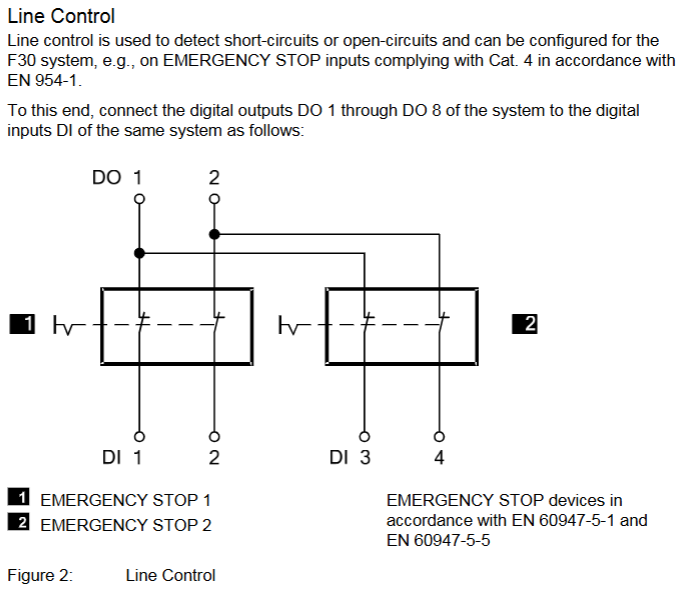
Digital input: 20 non isolated inputs, divided into 5 groups for power supply (4 in each group, LS+is a short-circuit protection 24V power supply), supports “power loss trip” logic (input is in a low-level safety state in case of fault), and can be configured with line control to detect short circuits/open circuits;
Digital output: 8 non isolated outputs, channels 1-3/5-7 have a rated current of 0.5 A (60 ° C), channels 4/8 support 1 A (60 ° C)/2 A (50 ° C), automatically turn off and periodically retry when overloaded, and trigger a fault alarm when short circuited;
Fault response mechanism: When an input/output fault (such as open circuit or output overload) is detected, a single channel fault only cuts off the corresponding channel. If the controller experiences an overall fault, all outputs are cut off, and the FAULT LED is activated and a fault code is reported (such as 0x0001 indicating input module fault and 0x0200 indicating total current exceeding the limit);
Self detection function: supports MOT (maintenance testing) and FTT (fault tolerance time) testing, detecting hardware faults (such as processor abnormalities), software errors (such as cycle time exceeding limits), and triggering output cutoff when overheating occurs (first level overheating code 0x0400, second level overheating code 0x0800).
(2) Hardware Structure and Interface
key parameters
|Storage capacity | Version<6.46:500 kB program/data; Version ≥ 7:1023 kB program/data; Version 6.100:2047 kB Program/Data | Adapt to User Programs of Different Complexity|
|Response time | ≥ 20 ms | Meet the real-time requirements of small and medium-sized security applications|
|Communication interface | 4 x RJ-45 (SafeEthernet), 3 x 9-pin D-sub (FB1/FB2/FB3, supports PROFIBUS/RS485, etc.) | Supports secure and standard communication protocols|
|Clock buffer | Integrated gold capacitor, maintains clock for about 1 week after power failure | Ensure time synchronization continuity|
|Dimensions (H × W × D) | 114 × 257 × 66 mm (including fasteners) | Weight approximately 1.2 kg, supporting 35 mm DIN rail installation|
Grouping and meaning of LED indicator lights
There are a total of 5 sets of LEDs on the front end of the controller, which perform a full light test when powered on. The status meanings of each indicator light are as follows:
Working voltage light (24 VDC, green): normally on indicates normal power supply, off indicates no voltage;
System lights (red/yellow, 6 lights):
RUN (green): Constant light indicates normal operation (executing user programs), slow flashing indicates STOP status or loading of operating system;
ERROR (red): Constant light indicates entering the ERROR STOP state (such as hardware failure), slow flashing indicates operating system failure requiring reloading;
ROG (yellow): Constant light indicates loading configuration, slow flashing indicates switching to STOP state or loading operating system;
FORCE (yellow): Constant light indicates that the forced function is activated in RUN state, and slow flashing indicates that it is ready to be forced in STOP state;
Communication light (green/yellow next to RJ-45): Green light constantly on indicates full duplex, flashing indicates conflict; A constant yellow light indicates a normal physical connection, while a flashing light indicates data transmission;
I/O light (DI 1-20/DO 1-8, yellow): normally on indicates that the channel is powered on (input valid/output engaged), off indicates that the channel is powered off (safe state);
Fieldbus light (FB1-3, yellow): The status changes with the protocol (such as always on when PROFIBUS communication is normal), please refer to the corresponding communication manual for details.
Reset button function
Reserve a reset hole in the upper left corner of the controller (triggered by an insulating pin), only for scenarios where the administrator account is forgotten or the IP address does not match: when restarting, press and hold the reset button for ≥ 20 seconds to restore the default parameters (IP: 192.168.0.99; SRS: 60000.0.0), and clear the user account (only the default administrator account is retained, password is empty). Attention: Before resetting, all fieldbus plugs must be unplugged to avoid interfering with communication with other devices.
Installation and configuration process
(1) Controller installation and wiring
Installation prerequisites
It needs to be fixed on a 35 mm DIN rail with reserved heat dissipation space around it (power loss of 12-33 W, avoiding close proximity to heating equipment);
Ex Zone 2 installation requires additional requirements: enclosure protection level ≥ IP54 (compliant with EN 60529), enclosure must be labeled with a “power off operation only” warning, equipped with a 10A delay fuse, PELV/SELV power supply, and reference to EN 60079-15 standard (terminal wiring, creepage distance, etc.).
Wiring specifications
Power wiring: Connect the positive terminal of the 24 VDC module to the “LS+” terminal, and the negative terminal to the “L -” terminal. Independent power supply is required to avoid collinearity with the power circuit;
Digital input wiring: 20 inputs are divided into 5 groups, each corresponding to independent “LS+” (sensor power supply) and “L -” (grounding), such as DI 1-4 corresponding to terminals 13 (LS+) -17 (DI4) -18 (L -), supporting passive contacts and active signals (corresponding to “L -” needs to be connected);
Digital output wiring: 8 outputs are divided into 2 groups, each corresponding to “LS+” (common terminal) and “L -” (ground). For example, DO 1-4 corresponds to terminals 1 (LS+) -5 (DO4) -6 (L -), channels 4/8 support high loads (2A @ 50 ° C), and inductive loads require parallel freewheeling diodes;
Communication wiring: RJ-45 interface connected to SafeEthernet network, supporting daisy chain topology; The D-sub interface (FB1-3) is connected to a fieldbus (such as PROFIBUS/RS485) and requires the use of shielded cables (single ended grounding of the shielding layer to reduce interference).
Line monitoring: Set the number of pulse channels (e.g. 1 indicates using DO1 pulse to detect the line), pulse delay (waiting time for line fault detection), and pulse slot (fixed at 3);
Fault monitoring: Enable MOT/FTT testing and read fault codes (such as 0x0010 indicating input short circuit, 0x0002 indicating output safety shutdown fault).
Input channel configuration (DI 20: Channels tab): Assign global variables to each input (DI1-DI20), set pulse channels (such as 1 for receiving DO1 pulses), and monitor single channel faults (such as 0x80 for open circuit);
Output channel configuration (DO 8: Channels tab): Assign global variables to each output (DO1-DO8), set output values (1=power on, 0=power off), and monitor single channel faults (such as 0x02 indicating channel overload).
ELOP II Factory configuration (version<7)
Assign system signals to I/O channels through the “Signal Editor”, with configuration parameters similar to SILworX. The core difference lies in the signal mapping method (based on “signal name channel” association rather than variable allocation), and the fault code is consistent with the state definition (such as Mod. Error Code 0x0010 indicating configuration error).
Operation, maintenance, and troubleshooting
(1) Daily operation and diagnosis
operation monitoring
Real time status can be viewed through LED: the RUN light is always on to indicate normal operation, the ERROR/AULT light is on to indicate a fault, and the I/O light corresponds to the channel status;
Detailed diagnosis: Read fault logs (such as line short circuit, output overload) through programming tools, support online viewing of I/O feedback values (ensure that instructions are consistent with actual status), SOE function records 5000 events (resolution 1ms) for easy fault tracing.
Common faults and solutions
|Fault phenomenon | Possible causes | Troubleshooting steps|
|All outputs are unresponsive (all I/O lights are off) | 1 The controller has not entered the RUN state; 2. The total current exceeds the limit; 3. Power supply failure | 1 Check the status of the RUN light (whether it is RUN); 2. Read DO. Error Code (whether it is 0x0200); 3. Measure the 24 VDC power supply|
|Single input fault (DI light off, fault code 0x80) | 1. Line open circuit; 2. Sensor power supply failure; 3. Pulse channel configuration error | 1 Check the input wiring (for looseness); 2. Measure LS+voltage (whether it is 24V); 3. Confirm that the pulse channel matches the DO configuration|
|Communication interruption (communication light off) | 1 IP address conflict; 2. Cable malfunction; 3. Mismatch of fieldbus protocol | 1 Check if the controller IP and PADT are on the same network segment; 2. Replace the communication cable; 3. Confirm that the fieldbus protocol (such as PROFIBUS slave address) is configured correctly|
(2) Maintenance and Lifecycle Management
regular maintenance
Operating system update: Utilize system downtime to load the latest version of the operating system through programming tools (the controller needs to be in STOP state), and backup the configuration before updating to avoid data loss;
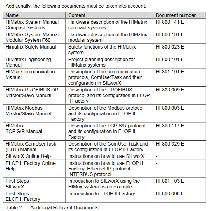
Proof Test: Conducted every 10 years, the test includes I/O channel continuity, line monitoring function, fault response (such as simulating overheating), and communication link integrity. Refer to the HIMA Safety Manual (HI 800 023 E).
Scrap and transportation
Scrap: Industrial users need to dispose of controllers containing electronic components in accordance with environmental protection requirements. They can contact HIMA to sign a scrap agreement, which prohibits the arbitrary disposal of controllers containing electronic components;
Transportation/Storage: Original anti-static packaging should be used to avoid mechanical impact, and the storage temperature should be maintained at -40…+85 ° C to avoid humid environments.