Call us 24/7uaedcs@163.com
Welcome to the official website of CNIACS Automation Technology Co., Ltd!
Call us 24/7uaedcs@163.com

Allied Telesis AT-TQ4400e Enterprise Outdoor

Core positioning and key characteristics

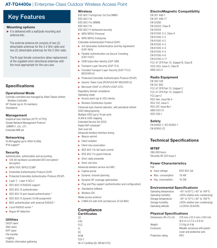
AT-TQ4400e is an enterprise level outdoor wireless access point launched by Allied Telesis, which focuses on stable wireless coverage and enterprise level functional support in outdoor scenarios. Its core features focus on flexible installation and antenna configuration:

Installation and antenna: standard wall/pole installation kit and antenna kit; The antenna includes 2 detachable 2.4GHz antennas and 2 detachable 5GHz antennas, and supports the replacement and adaptation of omnidirectional antennas for different scenarios through N-type female connectors, meeting diverse outdoor deployment needs.

Core functional specifications

1. Operation mode and management

Operation mode: Supports three core modes to meet different networking needs – centralized control by Allied Telesis Unified Wireless Controller (UWC), AP cluster (up to 16 members), and standalone operation.

Management method: Provide graphical user interface (HTTP/HTTPS), simple network management protocol (SNMP v1/v2 c/v3 *), and extended MIB set, balancing visual operations and standardized network management.

Note: The “” function requires software version v3.2.1 or above support, the same applies below.

2. Network and Security

Network capability: Supports VLAN tagging (up to 4094 VLANs) and IPv6 *, enabling fine-grained network partitioning and adaptation to next-generation network protocols.

Security protection:

Encryption and Authentication: 128 bit hardware accelerated AES encryption and decryption, supporting WPA/TKIP, WPA2/CCMP, as well as various authentication protocols such as EAP and PEAP; Compatible with IEEE 802.1X (including port based authentication *, dynamic VLAN allocation), MAC authentication (requiring external RADIOUS *), and built-in local Radius server *.

Risk prevention and control: equipped with Rogue AP detection (rogue AP refers to unauthorized access points that can prevent illegal devices from accessing the network), 2-4 layers of ACL * (access control list, restricting illegal traffic), to ensure network security boundaries.

3. Wireless function

Protocol and Performance: Compatible with IEEE 802.11a/b/g/n/ac, using 2×2:2ss MIMO technology; A single AP can support up to 200 client accesses, with 802.11ac speeds reaching 6.5-867Mbps (MCS 0-9, NSS 1-2) and 802.11n speeds ranging from 6.5-300Mbps, meeting high concurrency and high bandwidth requirements.

Wireless optimization: supports enhanced automatic channel selection (periodic refresh), SSID hiding/ignoring (up to 16 SSIDs per port), VLAN and SSID mapping, client isolation, maximum association limit, etc; It is also possible to implement captive portal, dynamic channel planning, dynamic RF coverage optimization, plug and play (authentication and configuration), and wireless IDS (intrusion detection system) through UWC.

Authentication Extension: The EAP protocol family covers all aspects, including EAP-AKA, EAP-FAST, EAP-SIM, EAP-TLS, EAP-TTLS/MSCHAPv2, PEAP (including PEAPv0/EAP-MSCHAPv2, PEAPv1/EAP-GTC), and is compatible with different enterprise authentication systems.

4. Practical tools

Built in DHCP client, DNS client, NTP client (time synchronization), supporting file transfer, logging, and statistical information collection, facilitating network deployment, maintenance, and problem troubleshooting.

Hardware and environmental specifications

1. Technical and physical parameters

MTBF (Mean Time Between Failures): 286269 hours (based on Telcordia SR 332 Issue 2 standard), excellent stability.

Power supply: Supports IEEE 802.3at PoE standard, with power consumption of 19.4W and 16.5W respectively.

Physical dimensions and weight: 218mm x 55.5mm x 250mm (8.6in x 2.2in x 9.9in), weight 2.0Kg (4.4lb), suitable for outdoor installation.

Protection level: IP67 (dustproof, short-term immersion), with a metal shell, plastic cover, and protective ventilation opening, suitable for harsh outdoor environments.

2. Environmental adaptability

Temperature: Operating temperature -40 ° C to 65 ° C (-40 ° F to 149 ° F), storage temperature -40 ° C to 70 ° C (-40 ° F to 158 ° F), strong resistance to high and low temperatures.

Humidity: Both working and storage humidity are ≤ 95% relative humidity (without condensation), suitable for humid environments.

Altitude: Working altitude ≤ 2000m (9843ft), covering most outdoor deployment scenarios.

Compliance and Certification

1. Product certification

Certified by CE, EAC, FCC, IC, KC, RCM, TUV-T, and Wi Fi Certified (ID: WFA61275), it meets the market access standards and wireless compatibility requirements of major global regions.

2. Electromagnetic compatibility (EMC) and wireless device compliance

EMC: Complies with EN 301 489-1/-17, EN 50385, EN 55022 (Class B), EN 55024, EN 61000 series standards, as well as FCC 47 CFR Part 15 Subpart B (Class B), ICES-003 Issue 5 (Class B), etc., to reduce electromagnetic interference to peripheral devices.

Wireless devices: comply with EN 300 328, EN 301 893, FCC 47 CFR Part 15 Subpart C/E/Part 2, RSS series standards, etc., to ensure compliant transmission of wireless signals.

3. Safety standards

Complies with EN 60950-1, IEC 60950-1, and EN 60950-22 safety standards to ensure electrical safety during equipment use.

Frequency and Modulation

1. Support frequency (subject to regulatory restrictions in various countries)

2.4GHz ISM band: 2.400~2.4835GHz

5GHz U-NII frequency band: 5.150~5.250 GHz(U-NII-1)、5.250~5.350GHz(U-NII-2A)、5.470~5.725GHz(U-NII-2C)、5.725~5.850GHz(U-NII-3)

2. Modulation technology

802.11a/g/n/ac: using OFDM modulation

802.11b: Uses DSSS, CCK, DQPSK, DBPSK modulation

802.11ac additionally supports BPSK, QPSK, 16QAM, 64QAM, 256QAM, and 802.11a/g/n supports BPSK, QPSK, 16QAM, and 64QAM to ensure signal quality at different rates.

3. Transmission power

The maximum transmission power exceeds 20dBm, and the signal strength will be automatically limited according to the selected regulatory domain and installed antenna, in compliance with local regulatory requirements.

Ordering and associated products

1. Ordering Information

The product model is AT-TQ4400e-xx, where “xx” represents the regulatory domain:

No suffix: globally applicable (except for the United States and Canada)

01: Exclusive for the United States and Canada (reserved)

2. Related products

AT-UWC-60-APL: Enterprise grade wireless LAN controller (hardware device) used for centralized control of APs

AT-UWC BaseST: Enterprise grade wireless LAN controller (software installation package, including 10 AP management licenses)

AT-TQ4600: Enterprise grade wireless access point (including IEEE 802.11ac dual band radio and built-in antenna), which can be used as a supplement for indoor or different scenarios.

UE 54 series pressure, vacuum, and temperature switches

Product Core Overview

The UE (United Electric Controls) 54 series is an OEM grade switch product that balances reliability and low cost, covering three monitoring types: pressure, vacuum, and temperature. It offers single/double SPDT (single pole double throw) output options and supports enclosed (NEMA 1 protection) or open (skeleton) structural designs. The product, with its compact size and flexible configuration, has been validated on-site in various fields such as medical equipment, laboratory instruments, fire protection, heating equipment, etc. It can meet the safety alarm and shutdown control requirements in different scenarios.

Core Features

Size and configuration flexibility:

Compact size, suitable for OEM applications with limited space;

Output options include 1 or 2 SPDT quick action switches, with a dual switch range separation of up to 100%, supporting “normally open” or “normally closed” wiring;

The setting method can be selected from the reference dial (intuitive adjustment) or the hexagonal socket screw (precise adjustment) to meet different operating habits.

Connection and protection options:

Pressure connection: optional 1/4 inch NPT (male/female), 1/2 inch NPT (female), some models provide polysulfone material 1/2 inch NPT (male) x 1/8 inch NPT (female) adapters;

Temperature component: equipped with a 6-foot copper or 304 stainless steel capillary tube, brass immersion probe, filled with non-toxic oil;

Protection level: Closed models (such as J54, B54) comply with NEMA 1 standards, while open models (with “S” suffix, such as J54S) have no protection and are suitable for customized enclosure scenarios.

Performance advantages:

High precision: The temperature setpoint deviates by less than 1% of the range as the ambient temperature changes (50 ° F/28 ° C), and the repeatability of the pressure/temperature setpoint reaches ± 1% of the full range (± 1.5% for 610-614 pressure models);

Anti interference: capable of withstanding 15G (10 milliseconds) impact, 2.5G (5-500Hz) vibration, and no drift at the set point;

Optional features: Some models support external manual reset (only reset when pressure/temperature rises) Viton ®  Enhanced options such as sealing material (suitable for special media).

Detailed technical specifications

(1) Environmental and physical parameters

Parameter category specification description

Environmental temperature range, pressure model:

-126-164 S164B、 610-614: -40 to 160 ° F (-40 to 71 ° C)

-22-28, 16008-16009:0 to 160 ° F (-18 to 71 ° C)

Temperature model: -40 to 160 ° F (-40 to 71 ° C)

Anti impact/vibration impact: The set point can be repeated after 15G (10ms); Vibration: The set point can be repeated after 2.5G (5-500Hz)

Enclosure Material Closed Model (J54, B54, etc.): Black Lexan ® (Polycarbonate), strong weather resistance

Weight approximately 12 ounces (approximately 340g)

Electrical connection aperture: J54/H54/C54, etc. are 7/8 inches, J54A is 1-1/16 inches

(2) Switches and electrical parameters

Parameter specifications

Switch output 1 or 2 SPDT channels, dual switch can be independently set, separation up to 100% range

Electrical rating – AC: Conventional model 15A 125/250/480VAC (resistive); 16008-16009 model 20A 480VAC

-DC: 24-30VDC (2A resistive/1A inductive), 125VDC (0.5A resistive/0.03A inductive)

(Note: DC capability is limited, special requirements need to be consulted with the manufacturer)

Dead zone (temperature/pressure difference) temperature model: Under laboratory conditions (70 ° F circulating bath, heating rate 0.5 ° F/minute), it is usually 1% of the range

Pressure model: varies with the model, for example, the 22 model is 1-3.5 inches of mercury vacuum, and the 614 model is 50-400psi

(3) Key parameters of pressure models (some core models)

Model adjustable set point range dead zone over range pressure (continuous withstand) withstand pressure (occasional withstand) pressure connection

22 30 inch mercury vacuum to 0psi (-1 to 0bar) 1-3.5 inch mercury vacuum (33.9-118.5mbar) 0psi (0bar) 50psi (3.4bar) 1/4 inch NPT (male), nitrile rubber diaphragm

25 10-100psi (0.7-6.9bar) 1-2.5psi (68.9-172.4mbar) 100psi (6.9bar) Exceeding the set point (no fixed value) 1/4 inch NPT (male), nitrile rubber diaphragm

126 30 inches of mercury vacuum to 0psi (-1 to 0bar) 0.2-0.9 inches of mercury (6.8-30.5mbar) 3psi (0.2bar) 5psi (0.3bar) 1/4 inch NPT (female), brass bellows

614 700-6000psi(48.3-413.7bar) 50-400psi(3.4-27.6bar) 6000psi(413.7bar) 10000psi(689.5bar) 1/4  Inch NPT (female), 303 stainless steel piston

S164B 4-200psi(0.3-13.8bar) 0.2-1psi(13.8-68.9mbar) 200psi(13.8bar) 200psi(13.8bar) 1/2  Inch NPT (female), 316L stainless steel corrugated pipe

(4) Key parameters of temperature models (some core models)

Model adjustable set point range, maximum temperature scale, indexing probe/bulb size (NPT x length), material

103 0-225 ° F (-17.8-107.2 ° C) 250 ° F (121.1 ° C) 10 ° F/5 ° C 3/8 × 2-1/8 inch brass probe

D20BC -130-120 ° F (-90-48.9 ° C) 170 ° F (76.7 ° C) 10 ° F/5 ° C 3/8 × 4-1/2 inch copper bulb+capillary tube

D23BS 150-650 ° F (65.6-343.3 ° C) 700 ° F (371.1 ° C) 25 ° F/10 ° C 3/8 × 4 inch 304 stainless steel bulb+capillary tube

D21BS 0-150 ° F (-17.8-65.6 ° C) 200 ° F (93.3 ° C) 5 ° F/5 ° C 3/8 × 7-1/4 inch 304 stainless steel bulb+capillary tube

Certification and Compliance

North American certification:

CULus certification: Pressure models (J54, H54, etc.) comply with UL 508, CSA C22.2 No.14 (document number E42272); Temperature models (B54, C54, etc.) comply with UL 873, CSA C22.2 No.24 (document number E10667);

CURus certification: Open models (J54S, B54S, etc.) are at the “approved” level and comply with the same standards mentioned above.

European certification:

Low Voltage Directive (LVD): 2006/95/EC (before April 20, 2016), 2014/30/EU (after April 20, 2016), except for models below 50VAC/75VDC;

Pressure Equipment Directive (PED): 97/23/EC (before April 20, 2016), 2014/34/EU (after April 20, 2016), except for models below 7.5psi;

Note: Open models are not subject to LVD control.

Ordering rules and options

(1) Model composition

You need to combine “Type+Model+Option”, for example: J54-25-0140 (J54 Type+25 Model+0140 Option).

Type selection: Classified by “Protection+Output+Adjustment Method”, the core types are as follows:

|Type | Application Scenario | Number of Output Channels | Protection Level | Adjustment Method|

|J54 | Pressure Monitoring, Conventional Closed Scenarios | 1-channel SPDT | NEMA 1 | Internal Hexagonal Screw (No Scale)|

|J54A | Pressure monitoring, dual output requirement | 2-channel SPDT | NEMA 1 | Hexagonal socket screw (without scale)|

|H54 | Pressure monitoring, requiring intuitive adjustment | 1-channel SPDT | NEMA 1 | Reference dial|

|B54 | Temperature monitoring (probe type), intuitive adjustment | 1-channel SPDT | NEMA 1 | Reference dial|

|E54 | Temperature monitoring (bulb+capillary), intuitive adjustment | 1-channel SPDT | NEMA 1 | Reference dial|

|With the suffix “S” (such as J54S, B54S) | Customized shell scene | 1/2 SPDT | Open | Corresponding adjustment method|

Option key code:

|Option code | Function description | Applicable restrictions|

|0140 | Gold plated contacts (1A 125VAC resistive) | Not suitable for 16008-16009|

|0500 | Narrow dead zone (5A 125/250VAC resistive) | Not applicable to B54, J54A, 16008-16009, etc|

|1530 | External manual reset (15A 125/250/480VAC) | Only applicable to H54, some pressure models, not applicable to open models|

|2000 | High current output (20A 125/250/480VAC) | Not suitable for 16008-16009|

|M501 | Polysulfone pressure connection (1/2 “NPT male x 1/8” NPT female) | Not suitable for pressure and temperature models such as 126-164 and 610-614|

(2) Additional temperature model options

Connection accessories: Provide 1/2 inch NPT union (brass/stainless steel), thermocouple sleeve (such as W191:1/2 inch NPT x 4 inch length, brass);

Scale unit: optional Celsius dial (only supported for some temperature models);

Identification label: Optional stainless steel label (up to 2 lines, 25 characters per line).

Installation and usage precautions

Extreme parameter control:

It is strictly prohibited to exceed the “withstand voltage” and “maximum temperature” limits (even short-term impact), and continuous operation should be within the “adjustable set point range” to avoid frequent switching near the limit value to extend the service life;

The ambient temperature should not exceed the product label range, and electrical connection holes should be sealed in humid environments to prevent water ingress.

Safety design:

Critical safety scenarios (such as personnel/equipment protection) require the configuration of backup switches and the installation of high and low limit protection to prevent loss of control;

The range of the set point should be reasonably selected to avoid unsafe conditions of the system caused by misoperation (such as excessive pressure and temperature).

Maintenance requirements:

Regularly verify the drift of the set point, and immediately check if any display abnormalities or action faults are found;

Do not disassemble or modify the product on your own. If customization is required, please contact the UE manufacturer;

Electrical wiring must comply with local regulations, and wire specifications should refer to the installation manual to avoid overload (the first overload may damage the switch).

Powell PowlVac ®  CDR&GCB Series 4 Vacuum Circuit Breaker

Product Core Overview

PowlVac ®  Series 4 vacuum circuit breaker is a new generation of metal armored vacuum circuit breaker launched by Powell Industries in the United States, suitable for medium and high voltage power systems ranging from 5kV to 38kV. Its design originated from the first PowlVac circuit breaker in 1982 and has been upgraded and optimized for multiple generations, combining compactness, high reliability, and low maintenance. The product focuses on ‘Powered by Safety’ ®”  The concept provides multiple customized options (such as narrow body design, manual/automatic rack and pinion transmission, intelligent monitoring equipment), which can adapt to the space limitations of existing equipment and meet the protection needs of medium and high voltage circuits in industrial, power and other fields.

Core design upgrade and features

(1) Key design upgrade

As a new generation product, Series 4 has undergone multiple optimizations in structure, compatibility, and maintainability, with the following core upgrade points:

Optimization of primary side disconnect components: Upgrade the primary side disconnect components of all 36 inch frame circuit breakers, improve the alignment tolerance between the circuit breaker and the cabinet installation pin components, and reduce installation difficulty; The contact components and circuit breaker pin components can be separated for easy maintenance and replacement, reducing downtime.

Universalization of secondary control wiring harness: For each type of circuit breaker frame size and rated value, the secondary control wiring harness is designed uniformly to simplify spare parts management and maintenance replacement processes.

32 pin secondary disconnect component upgrade: All Series 4 circuit breakers come standard with a 32 pin secondary disconnect component, which is designed for each frame size and includes Powell CBM ® Wiring of all control options for the Circuit Breaker Monitor device; Four pins are reserved for future communication function expansion.

Support integration of intelligent monitoring devices: All Series 4 frameworks and wiring harnesses are designed to be able to install CBM in the factory or on-site later ® (Circuit breaker monitor), without the need for large-scale renovation, enhances equipment intelligence and status monitoring capabilities.

Backward compatibility: Through minor modification, it can be compatible with the old PowlVac ®  Circuit breakers are completely interchangeable, reducing the cost of upgrading existing systems.

(2) Core functional characteristics

Compact design: Provides narrow body (PowlVac ND) ®) Model, meets the requirement of “reducing footprint” and adapts to the space limitations of existing equipment.

Rack Drive Options: All Series 4 circuit breakers can be optionally equipped with “onboard rack drive”, supporting both manual and automatic transmission modes to enhance operational convenience.

High durability: Short circuit breaking current rating coefficient K=1.0 (constant breaking rating), tested to achieve 10000 operations, with a long service life.

Low maintenance current transmission: Optimization of current transmission component design to reduce maintenance requirements and lower operation and maintenance costs.

Short term tolerance: With a 2-second short-term tolerance, it can withstand the impact of short-term short-circuit current and ensure system stability.

Detailed technical parameters (voltage level and rated value)

PowlVac ®  Series 4 circuit breakers are classified into voltage levels such as 5kV, 15kV, 27kV, 29.8kV, 38kV, etc. Different categories correspond to different frame sizes, short-circuit ratings, and continuous current ratings. The specific parameters are shown in the table below (“・” indicates that this specification supports corresponding continuous current):

Voltage level (kV) Product model Cabinet width (inches) Short circuit rating (kA) Lightning impulse withstand voltage (BIL, kV) Power frequency withstand voltage (kV) Continuous current rating (A)

1200A 2000A 3000A 5000A²

5kV PowlVac-ND ®  26 36 60 19 • • – –

5kV PowlVac-ND ®  26 50 60 19 • • – –

5kV PowlVac ®  36 36 60 19 • • • –

5kV PowlVac ®  36 50 60 19 • • • –

5kV PowlVac ®  36 63 60 19 • • • –

15kV PowlVac ®  36 25 95 36 • • • –

15kV PowlVac ®  36 36 95 36 • • • –

15kV PowlVac ®  36 50 95 36 • • • –

15kV PowlVac ®  36 63 95 36 • • • –

15kV PowlVac ®  36 63G¹ 95 36 • • • –

15kV PowlVac ®  36 48 63G¹ 95 36 – – •

27kV PowlVac-ND ®  36 25 125 60 • • – –

29.8kV PowlVac-ND ®  36 25 125 60 • • – –

27kV PowlVac ®  40 25 125 60 • • – –

27kV PowlVac ®  40 40 125 60 • • – –

38kV PowlVac ®  40 25 150 80 • • – –

38kV PowlVac ®  40 40 150 80 • • – –

38kV PowlVac ®  54 40 150 80 – – • –

Note: 1 63G represents the rated circuit breaker of the generator that meets the C37.013 standard test; 2. The 5000A circuit breaker is suitable for fixed metal enclosed applications and requires an isolation switch.

EMG Automation GmbH SV 1-10 servo valve

Product Core Overview

The EMG SV 1-10 servo valve is a single-stage 4/3-way proportional valve produced by EMG Automation GmbH in Germany. It adopts a patented electromagnetic rotary drive and reset spring design, complies with ISO 4401 NG10/Cetop 5 standards, and is suitable for precise control of flow and pressure in hydraulic systems. The equipment size is 127 × 72 × 264 (325) mm, and the weight is divided into 6.5kg and 7.5kg according to different versions. It can adapt to various hydraulic media such as mineral oil and is widely used in the field of industrial automation.

Model coding rules

The model code of SV 1-10 servo valve consists of 6 parts, each corresponding to specific parameters, which facilitates users to quickly identify product specifications. The specific rules are as follows:

Encoding position meaning optional parameters/description

Part 1 (SV) Product Type SV=Servo valve

Part 2 (1) Stage 1=single stage

Part 3 (10) nominal size 10=nominal size 10 (compliant with DIN 24340 standard)

Part 4 (e.g. 16) nominal flow rates 4, 8, 16, 32, 48 l/min (under PN=20 bar conditions)

Part 5 (e.g. 100) Fuel supply pressure 30-315 bar or 5-100 bar

Part 6 (such as 1/D) overlap amount/hydraulic oil type overlap amount: 1=1%, 6=6%;

Hydraulic oil: D=No specific reference (default mineral oil) C=HFC、D=HFD

Hydraulic parameter details

Hydraulic parameters are the core indicators for servo valve adaptation to hydraulic systems. The key parameters for different nominal flow rates (4/8/16/32/48 l/min) models are shown in the following table:

Hydraulic parameter specifications 4 l/min 8 l/min 16 l/min 32 l/min 48 l/min

Working pressure range (pS) with two pressure levels available: 30-315 bar or 5-100 bar (universal for all models)

The maximum allowable return oil pressure (pT) is uniformly limited to 30 bar for all models (universal for all models)

When the nominal flow rate (QN) Δ pN is 20 bar, the flow rate is 4 l/min, 8 l/min, 16 l/min, 32 l/min, and 48 l/min

When the nominal flow rate (QN) Δ pN=70 bar is 7 l/min, 13 l/min, 24 l/min, 46 l/min, and 70 l/min

External leakage flow rate without external leakage 0 (universal for all models)

Storage temperature range equipment storage environment requirements -20~+80 ° C (universal for all models)

Typical internal leakage flow rate (QO2) pS=100 bar, I=0 mA, t=50 ° C 0.4 l/min 0.6 l/min 1 l/min 1.5 l/min 2.2 l/min

Typical internal leakage flow rate (QO2) (Ex version, same as above) 0.4 l/min 0.7 l/min 1.2 l/min 1.8 l/min 2.8 l/min

Typical internal leakage flow rate (QO2) SV1-10/…/50/6 and Ex versions 0.7 l/min 1.2 l/min 1.8 l/min 2.8 l/min 3.8 l/min

Hysteresis flow control accuracy index<2%<2%<2.5%<2.5%<2.5%

Lag deviation control signal response stability<0.1%<0.1%<0.2%<0.2%<0.2%<0.2%

Correlation between sensitivity signal changes and flow response<0.1%<0.1%<0.2%<0.2%<0.2%

Nonlinear flow rate and linearity of control signals<2%<3%<4%<5%<6%

Asymmetric flow, consistency of flow in both directions<5% (universal across all models)

Overlap amount 1% Overlap amount model (../…/1) 0.5~2.5% (universal for all models)

Overlap amount 6% Overlap amount model (../…/6) 4-8% (universal for all models)

The influence of zero temperature drift on the zero flow point theoretically has no drift and cannot be measured (applicable to all models)

Recommended hydraulic medium compatible with mineral oil VG46 (compliant with DIN 51524) or HLP/HVLP VG46 (compliant with DIN 51524/ISO 6743-4); HFC and HFD require consultation with manufacturers

Recommended filtration precision: Hydraulic oil cleanliness requirements: Filtration grade 17/15/12 (ISO 4406:1999), grade 7 (SAE AS 4059), grade 6 (NAS 1638) (applicable to all models)

Electrical parameter details

Electrical parameters determine the compatibility between servo valves and control systems, mainly involving indicators such as current, resistance, inductance, etc., as follows:

Electrical parameter connection terminal (1-2) specifications 4 l/min 8 l/min 16 l/min 32 l/min 48 l/min

Rated current Normal operating current range ± 300 mA ± 300 mA ± 300 mA ± 300 mA ± 1000 mA

Rated jitter signal (50Hz) high-frequency signal compensation 10 mA 10 mA 20 mA 20 mA 40 mA

Rated jitter signal (150Hz) high-frequency signal compensation 20 mA 20 mA 40 mA 80 mA

Resistance coil resistance value 40 Ω 40 Ω 40 Ω 44 Ω 11 Ω

Inductance coil inductance value 0.16 H 0.16 H 0.16 H 0.2 H 0.05 H

Electrical parameter connection end (1-3) specifications 4 l/min 8 l/min 16 l/min 32 l/min 48 l/min

Rated current Normal operating current range ± 600 mA ± 600 mA ± 600 mA ± 600 mA-

Rated jitter signal (50Hz) high-frequency signal compensation 20 mA 20 mA 40 mA 40 mA-

Rated jitter signal (150Hz) high-frequency signal compensation 40 mA 40 mA 80 mA 80 mA-

Resistance coil resistance value 20 Ω 20 Ω 20 Ω 22 Ω-

Inductance coil inductance value 0.08 H 0.08 H 0.08 H 0.1 H-

General Electric Parameter Specifications

Three core cable plug with protective contacts, compliant with DIN 43650 standard

Protection level IP 65 (with plug tightened)

image.png

West 2300 1/32 DIN Indicator and Controller

Product Core Overview

The West 2300 is a 1/32 DIN specification multifunctional device that combines indicator and controller functions. It is compact in size but fully functional. Equipped with a 10mm high large display screen (optional in red or green), built-in 2A relay, supports full 3-wire PT100 input, and the controller version is also equipped with the manual free Easy Tune PID algorithm, which can meet the monitoring and control needs of temperature, current and other parameters in industrial scenarios.

Core functions and features

(1) Functional mode

Provide three core functional versions to adapt to different application scenarios:

Three types of PID controllers: equipped with PID regulation function, supporting Easy Tune, manual tuning, and pre tuning.

Indicator with alarm: only monitors parameters and triggers alarms, without control output.

Pure indicator: only used for parameter display, without alarm and control functions.

(2) Key characteristics

Setpoint Lock: Restricting the operator’s permission to modify the controller’s set values to avoid erroneous operations affecting system stability.

Flexible output configuration: Supports up to 3 outputs, with a maximum of 1 for control and 2 for alarm. Relays or SSR (Solid State Relay) outputs can be configured according to requirements.

Dual alarm type: supports two types of alarm functions, with alarm triggering conditions including “high process value”, “low process value”, “set value deviation”, and “interval alarm”.

Humanized operation interface: adopting a 3-button operation design, paired with a 4-digit 10mm high LED display screen (red/green optional), and equipped with “control”, “settings”, “alarm”, “set value” indicator lights, with clear status visualization.

Sensor disconnection detection: When the sensor (thermocouple, RTD, etc.) is disconnected, it can respond quickly (except for the 0-20mA range, the response time is less than 2 seconds). At this time, the control output is turned off, the thermocouple/mV range triggers a high alarm, and the RTD/mA range triggers a low alarm, improving system safety.

Detailed technical specifications

(1) Input parameters

Input type, specific specifications

Thermocouples support seven types: J, K, R, S, T, B, and N

RTD (Platinum Resistance) 3-wire PT100, with a maximum of 50 Ω per lead (to be balanced)

DC Linear signal supports 0-20mA, 4-20mA, 0-50mV, 10-50mV, with a scalable range (-1999 to 9999), and the decimal point position can be set as needed

Input impedance thermocouple and mV range:>10M Ω; mA range: 4.7 Ω

Accuracy input range ± 0.1% (± 0.25% for J and T-type thermocouples), ± 1 LSD (least significant bit); Thermocouple cold junction compensation (CJC) accuracy better than 0.7 ° C

Sampling rate of 4 times per second, resolution of approximately 14 bits

(2) Output and Communication Options

Control and alarm relays:

Contact type: SPDT (single pole double throw), 2A/240V AC under resistive load; If communication or second relay is configured, all relay contacts will become SPST (single pole single throw).

Lifespan:>500000 operations.

Control SSR output: Drive capability>10V DC, minimum load 500 Ω.

Communication function: Supports 2-wire RS485, baud rate 1200-9600, compatible with Modbus protocol (optional for some models only, specified upon order).

(3) Work and environmental conditions

Temperature: Operating temperature 0-55 ° C, storage temperature -20-80 ° C.

Humidity: 20% -95% RH (non condensing).

Power supply: standard 100-240V AC 50/60Hz (7.5VA); Optional 12-24V AC (7.5VA) or 12-30V DC (4W).

Protection level: front panel IEC IP66, rear panel IP20.

Certification: Complies with CE, UL, and ULc standards.

(4) Physical dimensions

Key dimensions (approximate): 10mm (display height), 45mm ± 0.6 (certain dimension), 49mm, 100mm, 22mm ± 0.3, 25mm (specific installation dimensions need to be based on actual layout reference).

On site reconfiguration and ordering information

(1) On site configurable items

Some functions can be adjusted on-site without the need for additional accessories:

Input type: Can be reconfigured between supported input types (thermocouple, RTD, DC linear signal).

Control/Alarm 1 Output (Controller Version Only): Can be switched to “Relay Control+SSR Alarm 1” or “SSR Control+Relay Alarm 1”.

(2) Cannot be configured on-site

It needs to be confirmed at the time of the order and cannot be added or modified later:

Hardware options, such as RS485 communication function and second alarm relay, can only be selected at the time of ordering whether to install them.

(3) Order Code Rules

The ordering code consists of three parts: product model (N2300), output type, display color and power supply, and options. The specific code corresponds to the following:

Output type (second digit)

|Encoding | Output Configuration|

|00 | (not clearly marked, needs to be confirmed based on actual needs)|

|01 | Indicator+Alarm 1 (Relay)|

|02 | Indicator+Alarm 1 (SSR)|

|12 | Controller (relay)+Alarm 1 (SSR)|

|21 | Controller (SSR)+Alarm 1 (Relay)|

Display color and power (third digit)

|Encoding | Configuration|

|0 | Green display screen/100-240V AC power supply|

|1 | Red display screen/100-240V AC power supply|

|2 | Green display screen/12-30V DC/24V AC power supply|

|3 | Red display screen/12-30V DC/24V AC power supply|

Option (fourth place)

|Encoding | Options|

|0 | No additional options available|

|1 | Install a second alarm relay output|

|2 | Install RS485 communication function|

Foxboro Evo ™  FBM242 Discrete Output Module

Module Core Overview

FBM242 is Schneider Electric Foxboro Evo ™ The external power supply discrete output module in the process automation system has 16 discrete output channels, which can adapt to common voltages and currents in industrial scenarios. It requires an external power supply to power the field circuit and can achieve electrical output signal interaction between the control processor and field devices. It supports digital I/O applications (including ladder logic) and provides output fault safety configuration options.

Key characteristics

Channel and voltage support: Includes 16 discrete output channels, compatible with various voltage signals including 15-60V DC, 120V AC/125V DC, and 240V AC.

Isolation protection: Each input and output adopts galvanic isolation (electrical isolation), and when combined with external excitation, it is group isolation, which can avoid interference between different channels and ground.

Environmental adaptability: Adopting a sturdy design, the shell is made of extruded aluminum, which can be installed in G3 level (harsh) environments that comply with ISA standard S71.04, and can withstand vibration (7.5m/s ², 5-500Hz).

Configurable functions: When executing discrete I/O or ladder logic programs, options such as input filtering time, fail safe configuration, fail safe fallback, and continuous/instantaneous output can be configured.

Visual indication: The front of the module is integrated with LED indicator lights, which can display the running status of the module and the discrete status of each output point, facilitating real-time monitoring.

Convenient maintenance: Modules can be disassembled and replaced without dismantling on-site equipment wiring, power or communication cables, reducing maintenance downtime.

Communication redundancy: Connected to the fieldbus communication module (FCM) or control processor (FCP) through a redundant 2Mbps fieldbus, the two communication paths (A/B) can automatically switch to ensure communication continuity.

Safety design: The on-site power supply of contacts or solid-state switches has current limiting protection to ensure the safety of equipment and personnel.

Detailed technical specifications

(1) Output channel parameters

Parameter values

Number of channels: 16 isolated channels

Maximum application voltage 15-60V DC

Load current single channel maximum 2.25A

At surge current of 30 ° C, the maximum current in a single channel within 20ms is 8A; at 70 ° C, the maximum current in a single channel within 20ms is 6.4A

Maximum 0.2V when the on state voltage drop is 2.25A

Maximum open state leakage current of 0.1mA

Inductive load protection requires connecting protective diodes or metal oxide varistors (MOVs) at both ends of the inductive load

Isolate and withstand voltage between any channel and ground, between any two channels, apply 600V AC voltage for 1 minute without damage (note: do not operate at this voltage for a long time, otherwise it violates safety regulations and poses a risk of electric shock)

(2) Power supply and power consumption

Input voltage range (redundant): 24V DC (± 5%/-10%)

Maximum power consumption: 3W at 24V DC

Maximum heat dissipation: 6.5W when 24V DC and all outputs are 1.5A

(3) Environmental specifications

Environmental Condition Module Terminal Component (PA)

Working temperature -20 to+70 ° C (-4 to+158 ° F) -20 to+70 ° C (-4 to+158 ° F)

Working humidity 5% -95% (non condensing) 5% -95% (non condensing)

Working altitude -300 to+3000m (-1000 to+10000ft) -300 to+3000m (-1000 to+10000ft)

Storage temperature -40 to+70 ° C (-40 to+158 ° F) -40 to+70 ° C (-40 to+158 ° F)

Storage humidity 5% -95% (non condensing) 5% -95% (non condensing)

Storage altitude -300 to+12000m (-1000 to+40000ft) -300 to+12000m (-1000 to+40000ft)

(4) Physical specifications

Installation method: The module is installed on a modular base plate, which can be DIN rail mounted (horizontal/vertical) or horizontally mounted on a 19 inch rack through an installation kit; The terminal assembly (TA) is installed on a DIN rail (compatible with 32mm and 35mm specifications).

Weight: The module weighs approximately 284g (10oz); The weight of terminal components varies depending on their specifications, with the 127mm model weighing approximately 272g (0.60lb), the 148mm model weighing approximately 285g (0.65lb), and the 216mm model weighing approximately 320g (0.70lb).

Module dimensions: height 102mm (4in, including installation ears 114mm/4.5in), width 45mm (1.75in), depth 104mm (4.11in); The size of the terminal component should refer to the corresponding model (such as RH917XX width 127mm, etc.).

Terminal Components (TAs) Details

(1) Core functions

The terminal components are installed through DIN rails to connect the on-site I/O signals with the FBM subsystem, providing functions such as signal conditioning, surge light isolation, external power connection, and fuse protection. In most scenarios, no additional terminal equipment is required.

(2) Classification and specifications

Low voltage discrete output TA: suitable for<60V DC voltage, with split band fuse protection (single channel 3.15A filled fuse, current limiting 2A) and no fuse protection (users need to configure intermediate relays or fuse terminal blocks between TA and on-site equipment themselves). The power supply can come from FBM 24V DC auxiliary power supply or on-site power supply.

High voltage discrete output TA: Suitable for 120V ac/240V ac voltage, using plug-in SPDT (Form C) electromechanical relays or solid-state switches, relays can be replaced on site, supporting mixed voltage, high and low voltage signal isolation layout, power supply needs to be provided externally, some models include power distribution function (power supply positive pole fuse, negative pole connected to site).

(3) Partial TA models and parameters (compatible with FBM242)

TA model output signal terminal type cable type certification type

RH916JY (replacing P0916JY) 16 channel, with fuse, 15-60V DC (external supply), 2A max, FBM isolation C (crimping terminal) 4, 4H 1, 2

RH917XX (replacing P0917XX) 16 channels, no fuse, 15-60V dc (external supply), 2A max, FBM isolation C 4, 4H 1, 2

RH923LL (replacing P0923LL) 16 channel, SPDT relay (with LED),<30V DC 5A/125V DC 600mA (resistive)/240mA (inductive)/250V AC 5A, TA relay isolation C 4 5

RH926BE (replacing P0926BE) 16 channel, solid-state switch (with fuse), 125V ac/125V dc 2A max, TA isolated Knife (blade terminal) 4 5

Cable and certification related

(1) Terminal cable

Specification: 37 pin male D-subminiature interface, with a maximum length of 30m (98ft), made of polyurethane or low smoke halogen-free (LSZH) material, divided into Type 4 and Type 4H types (Type 4H is suitable for>5m long distance wiring to reduce voltage drop).

Partial cable models: 0.5m Type 4 RH916FG, 10m Type 4H RH916GE, 30m LSZH RH928BK, etc. (refer to Table 2 for details).

(2) Certification compliance

Electromagnetic compatibility (EMC): Complies with the EU EMC Directive 2004/108/EC (before April 20, 2016), 2014/30/EU (after April 20, 2016), and meets the EN61326-1:2013 Class A emission and industrial immunity levels.

Environmental compliance: Compliant with the EU RoHS Directive 2011/65/EU.

Safety certification: UL/UL-C certification, applicable to Class I A-D Group 2 T4 temperature code enclosure systems; DEMKO certified Ex nA IIC T4, suitable for Zone 2 hazardous environments; Classification certification (ABS type approval, French Classification Society EC31 environmental category certification).

TA certification type description: Type 1 (UL/UL-C Class I A-D Group 2 Zone T4, DEMKO Ex nA IIC T4), Type 2 (UL/UL-C associated equipment, DEMKO Zone 2 IIC associated equipment, Class 2 limited energy), Type 4 (Class 2 limited energy), Type 5 (only applicable to ordinary non hazardous locations).

Emerson MVME6100 series VMEbus single board computer

Product positioning and core values

The MVME6100 series is the first VMEbus single board computer (SBC) launched by Emerson Network Power, which uses the Tundra Tsi148 VMEbus interface chip and focuses on “business critical continuity embedded computing”. Its core advantage lies in achieving a bus transmission rate of 320MB/s through the 2eSST VMEbus protocol, while balancing the performance of the processor, memory, local bus, and I/O subsystem. It can meet the high reliability and high bandwidth embedded computing needs of defense aerospace, industrial automation, medical imaging, and other fields, and is compatible with existing VMEbus infrastructure to protect users’ existing investments.

Core hardware specifications

(1) Processor and computing power

Component parameter details

Main processor MPC7457 PowerPC ®  Processor, maximum clock speed 1.267GHz

128 bit AltiVec coprocessor, supporting parallel processing, suitable for data intensive applications

Cache configuration on-chip L1 cache (instructions/data): 32K/32K; On chip L2 cache: 512K; L3 cache: 2MB

(2) Storage system

Storage type parameter details

Main memory DDR ECC SDRAM, speed 133MHz (DDR266), maximum capacity 2GB (onboard), supports 512MB/1GB/2GB configurations

128MB onboard programmable EEPROM flash memory, divided into two 64MB storage banks, supporting jumper write protection

Non volatile memory (NVRAM) capacity of 32KB (user usable 4KB), storage life of 50 years at 55 ° C, service life of 5 years at 100% duty cycle at 25 ° C, equipped with replaceable battery

(3) Bus and Interface

VMEbus interface

Protocol compatibility: ANSI/VITA 1-1994 (VME64), ANSI/VITA 1.1-1997 (VME64 extension) VITA 1.5(2eSST)

Transmission performance: Under the 2eSST protocol, the actual bandwidth reaches 320MB/s

Function support: DTB main device (A16/A24/A32/A64 addresses, D08-D64 data, supporting SCT/BLT/MBLT/2eVME/2eSST); DTB from equipment (including UAT function); RR/PRI Arbitrator; 7-way IRQ interrupt processing/generation; System controller with jumper or automatic detection capability; 2 LMA32 position monitors

Compatibility: Equipped with Texas Instruments’ new VMEbus transceiver, it can be connected to standard VMEbus backboards and is compatible with existing VMEbus boards, backboards, chassis, and software

PCI and Expansion Interface

2 33/66/100 MHz PMC-X slots: support industry standard PMC/PrPMC modules, expandable for application specific functions (such as multiprocessors)

32/64 bit 33/66 MHz PCI expansion interface: supports PCI expansion carriers such as Emerson PMCSpan

64 bit/133 MHz PCI-X bus: connects Tsi148 VMEbus interface chip with PMC-X slot to ensure high bandwidth transmission

network interface

Dual Gigabit Ethernet interface, controller integrated into host bridge, speed 10/100/1000Mbps

Connection method: 1 router to front panel RJ-45, 1 can be routed to front panel RJ-45 or P2 interface (10/100Mbps router to MVME761 RJ-45 in IPMC mode, gigabit router to P2 in PMC mode)

serial interface

Asynchronous serial ports: 2 16550 compatible ports, EIA-574 DTE configuration, maximum baud rate of 38.4Kbps (EIA-232)/115Kbps (raw rate), 1 routed to front panel RJ-45, 1 used for development

Extended serial port (requires IPMC module): IPMC761 provides 2 asynchronous+2 synchronous ports, IPMC712 provides 3 asynchronous+1 synchronous port, supports EIA-232/DCE/LTE configuration

Other interfaces

Parallel port: Supports IEEE 1284 standard (MVME761 for HD-36 interface, MVME712M for D-36 interface, Centronics compatible)

SCSI interface: The IPMC module is equipped with Symbios 53C895A controller, supporting 8-bit (5.0MB/s asynchronous) and 16 bit (20.0MB/s Ultra SCSI), and needs to be connected through a P2 adapter

Software support

(1) Firmware and Debugging

Onboard firmware (MOTLoad): stored in flash memory, providing power on self-test (POST), system initialization, and operating system boot functions, supporting debugging interfaces similar to “bug” (compatible with OEM VMEbus boards)

(2) Operating System

Support real-time operating system (RTOS) and kernel: Provides VxWorks board level support package (BSP), Lynx OS BSP, and Linux system support

(3) Library and Protocol

BETA 4.0 NDDS (real-time publish/subscribe middleware) supporting Real Time Innovations (RTI), which can run through Gigabit Ethernet or native VME; NDDS 4.0 under the 2eSST protocol can be obtained through Emerson bundled models

Key functions and features

(1) Performance balance

The host bridge (Marvel MV64360) supports 133MHz host bus and 133MHz DDR memory bus, matching processor speed; Dual PCI-X buses are respectively connected to the VMEbus interface and PMC slot to avoid bandwidth bottlenecks

(2) Backward compatibility

It can be migrated from Emerson’s previous generation products (MVME2300/2400 controllers, MVME2600/2700/5100/5500 SBC), compatible with existing hardware (such as VME backboards, I/O modules) and software, simplifying the upgrade process

(3) P2 I/O mode and transition module

P2 I/O mode (jumper configuration)

PMC mode: compatible with MVME2300/2400/5100/5500, P2 interface provides 64 pin deep I/O for PMC slot 1 and 46 pin deep I/O for slot 2

IPMC mode: When inserting the IPMC761/712 PMC card, it supports MVME761/MVME712M legacy I/O modules (PMC I/O function is limited), and PMC slot 2 is reserved for expanding SCSI signals

Transition module

MVME761: Provides IEEE 1284 parallel port, 10/100BaseT Ethernet (RJ-45), 2 DB-9 asynchronous serial ports (EIA-574 DTE), 2 HD-26 synchronous/asynchronous serial ports (EIA-232/DCE/LTE can be configured through SIM), requiring 3/5 rows of P2 adapters (5 rows support 16 bit SCSI)

MVME712M: Provides Centronics parallel port, narrow SCSI port, 4 DB-25 asynchronous/synchronous serial ports (with jumper configuration EIA-232), 5 rows of P2 adapters supporting additional user-defined I/O

(4) Environmental adaptability and reliability

Environmental parameter operating status Non operating status

Temperature: 0 ° C~+55 ° C (intake temperature under forced air cooling) -40 ° C~+85 ° C

Humidity (non condensing) 5%~90% 5%~90%

Vibration 6 Gs RMS (20-2000 Hz random) 6 Gs RMS (20-2000 Hz random)

Mean Time Between Failures (MTBF) in a ground fixed uncontrolled environment: 178403 hours; Ground benign controlled environment: 328698 hours

Safety compliance: Printed Circuit Board (PWB) flame retardant rating UL 94V-0

EMC Compliance: Compliant with FCC Part 15 Subpart B Class A (USA), ICES-003 Class A (Canada), EU EMC Directive 89/336/EEC (EN55022 Class A emission, EN55024 immunity)

Applicable fields and values

(1) Defense and Aerospace

Adaptation scenarios: shipborne shielding systems, ground fixed systems, reconnaissance aircraft command and control applications

Core value: 1.267GHz processor+100MHz PMC bus+8x VME bandwidth, eliminating bottlenecks in traditional command and control systems; Support PrPMC expansion for multiple processors without the need for additional heat dissipation and I/O management; Compatible with existing VME infrastructure, reducing upgrade costs

(2) Industrial automation

Adaptation scenarios: Semiconductor Processing Equipment (SPE), Automatic Test Equipment (ATE), High end Industrial Control

Core value: High bus bandwidth and processing speed improve production efficiency; AltiVec technology supports vector processing; Dual PMC slots with customizable functionality; Backward compatibility ensures reuse of existing devices (such as sensors and actuators)

(3) Medical imaging

Adaptation scenarios: Nuclear Medicine (NM), Positron Emission Tomography (PET), Magnetic Resonance Imaging (MRI), X-rays, Computed Tomography (CT)

Core value: 2eSST protocol increases VME transmission rate by 8 times, meeting the requirements of image intensive computing; Compatible with existing VME systems to protect software and hardware investments; Reduce the number of embedded boards and alleviate equipment space pressure

Product specifications and ordering information

(1) Physical specifications

Dimension parameters

Height 233.4 mm (9.2 in.)

Depth 160.0 mm (6.3 in.)

Front panel height 261.8 mm (10.3 in.)

Width 19.8 mm (0.8 in.)

Maximum component height 14.8 mm (0.58 in.)

Weight Scanbe handle: 425 g (15 oz.); IEEE controller: 468 g (16.5 oz.)

(2) Power requirements (excluding PMC/IPMC modules)

Input voltage:+5V ± 5%

Current: MVME6100 single machine – typical 8.4A, maximum 10.2A; MVME6100+MVME761- typical 9.2A, maximum 11.2A

IPMC module additional power consumption:+5V maximum 0.5A,+3.3V maximum 0.75A (IPMC761/IPMC712 universal)

(3) Ordering model (main model)

New model replacing old model description

MVME61006E-0161R MVME61006E-0161 1.267GHz MPC7457512MB DDR, 128MB flash memory, Scanbe controller

MVME61006E-0163R MVME61006E-0163 1.267GHz MPC7457512MB DDR, 128MB flash memory, IEEE controller

MVME61006E-0171R MVME61006E-0171 1.267GHz MPC7457, 1GB DDR, 128MB flash memory, Scanbe controller

MVME61006E-0173R MVME61006E-0173 1.267GHz MPC7457, 1GB DDR, 128MB flash memory, IEEE controller

MVME61006E-2173R MVME61006E-2173 1.267GHz MPC7457, 2GB DDR, 128MB flash memory, IEEE controller

MVME61006E-0173CR MVME61006E-2173C 1.267GHz MPC7457, 2GB DDR, 128MB flash memory, IEEE handle, conformal coating (corrosion-resistant)

(4) Related accessories

PMCSPAN series: PMCSPN26E-002/010 (IEEE controller), PMCSPN16E-002 (Scanbe controller)

P2 Adapter and Transition Module: MVME7616E-011 (5-Row P2 Adapter+Transition Module), MVME761P26E-011 (5-Row P2 Adapter Only), MVME7616E-001 (3-Row P2 Adapter+Transition Module), MVME761P26E-001 (3-Row P2 Adapter Only), MVME712M6E (Transition Module), MVME712P2-6E (P2 Adapter)

Okonite Type SP-OS ITC/PLTC Instrument Cable

Product basic positioning

Okonite Type SP-OS cable belongs to the ITC/PLTC (Instrument Tray Cable/Power Limiting Tray Cable) category, with multi shielded pairs or three wire group structure and overall shielding design, rated voltage of 300 volts, temperature tolerance level of 105 ° C, designed specifically for cable tray scenarios, and meets multiple industry standards, suitable for electrical environments with high requirements for shielding and anti-interference.

Core specification parameters

(1) Conductors and Insulation

Category specific parameters

The conductor material is bare soft annealed copper, which meets the ASTM B-8 standard and adopts a 7-strand concentric structure; The communication cable is a 22 AWG solid bare copper wire with a 12 mil flame-retardant Okoseal insulation layer ® (PVC), Tolerant to 105 ° C

Insulation using flame retardant Okoseal ® (PVC) material, compliant with UL 13 and UL 2250 standards, nominal thickness of 15 mil, temperature rating of 105 ° C; X-Olene is recommended for special scenarios (DC applications in humid environments) ®  insulation

The conductor identification lines are colored in black and white; The three line group consists of black, red, and white; White conductor with numbers printed on it, used for group identification

(2) Shielding structure

Group shielding: Using aluminum/polyester tape overlapping wrapping to achieve 100% coverage, equipped with 7-strand tinned copper lead wires (two sizes smaller than conductors), and all group shields are completely isolated from each other to prevent crosstalk or capacitive coupling between adjacent wire pairs (especially for AC signals and pulse signals).

Cable overall shielding: Aluminum/polyester tape is also used to overlap and wrap to achieve 100% coverage. The drainage wire is made of 7-strand tinned copper with the same size as the conductor, which can isolate most of the static interference generated by the radiated electric field of power cables and other electrical equipment.

(3) Assembly and Sheath

Assembly method: Assemble wire pairs or three wire groups in a left twisted manner; If necessary, add flame-retardant and non absorbent fillers to ensure that the cable has a circular structure.

Sheath: Black flame retardant low-temperature Okoseal ®  Materials that comply with UL 13 and UL 2250 standards; A tear rope is longitudinally laid under the sheath for easy peeling.

(4) Electrical performance

Specific values of electrical indicators (different specifications)

Conductor resistance (20 ° C, per 1000 feet) 20 AWG: 10.4 ohms; 18 AWG: 6.5 ohms; 16 AWG: 4.1 ohms

Insulation test voltage (spark test) 5000 volts AC

Dielectric test voltage 1500 volts AC, lasting for 15 seconds

Insulation resistance constant (60 ° F, minimum value, typical value for natural materials) 2000 megaohms -1000 feet

Loop resistance (2 conductors, 20 ° C, every 1000 feet) 20 AWG: 2.8 ohms; 18 AWG: 13.0 ohms; 16 AWG: 8.2 ohms

Mutual capacitance (typical value, picofarads per foot) 20 AWG: 59; 18 AWG:68; 16 AWG:76

(5) Classification and Compliance

Obtained UL certification, listed as ITC/PLTC cable, can be used in accordance with Article 335 and Article 722 of the 2023 National Electrical Code.

Compliant with UL 2250 (ITC standard), UL 13 (PLTC, CL2, CL3 standard); It can also be used as a power limited fire-resistant signal cable (FPL) that complies with NEC Article 760 and is certified by OSHA.

Applicable scenarios

Circuit and Power Range: Suitable for ITC unclassified or non labeled circuits (voltage up to 150 volts, current up to 5 amps, power 750 volt amperes), as well as Class 2 or Class 3 power limiting circuits.

Environmental conditions: Can be used both indoors and outdoors; Adapt to humid or dry environments (maximum working temperature of conductors is 105 ° C, low temperature installation tolerance is -40 ° C); Can be used for cable trays, cable trays, scenes supported by overhead wires, and under raised floors.

Dangerous Area: Suitable for Class 1, Zone 2, Zone 2, and Zone 2 hazardous areas.

Functional requirement: It is necessary to shield external interference to the greatest extent possible, or to shield between wire groups (especially when cables may be subjected to abnormally high current or voltage interference); The cable has a built-in communication line that can be used for voice communication during installation or instrument calibration.

Product Features

Flame retardant performance: Passed UL 13 and IEEE 383-1974 vertical tray combustion tests.

Weather and chemical resistance: resistant to sunlight and oil, with excellent weather resistance.

Anti interference capability: 100% shielding coverage, reduces electromagnetic noise pickup, and has good external noise suppression effect.

Convenience of use: Strong flexibility, easy to operate and end connect; Complete isolation of wire pairs or three wire groups, precise shielding effect.

Other supplementary information

(1) Cable tray filling calculation

The cross-sectional area of the cable needs to be calculated according to NEC Article 392.22 to determine the reasonable filling amount of the cable tray.

(2) Length tolerance

When cutting lengths of 1000 feet or more, the tolerance is ± 10%.

When the cutting length is less than 1000 feet, the tolerance is ± 15%.

Honeywell SPS series intelligent position sensor

Product Description

Positioning: A durable, adaptable, and lightweight linear position sensor in the industrial field that can achieve high-precision motion control, improve operational efficiency and safety.

Design features: Adopting non-contact design, eliminating mechanical failure mechanisms, reducing wear and tear, improving reliability and durability, and reducing downtime.

Core function: Used for absolute position detection, using patented combination technology (ASIC dedicated integrated circuit+MR magnetic resistance sensor array) to accurately and reliably detect the position of magnets attached to moving objects, thereby determining or controlling the position of the object.

Detection principle: The MR array measures the output of MR sensors installed along the direction of magnet motion, determines the pair of MR sensors closest to the center of the magnet through the output and MR sensor sequence, and then uses the outputs of these two sensors to determine the position of the magnet between them.

Output type: Provides analog output with 3 different detection range configurations, namely 0-35mm (0-1.38 inches), 0-75mm (0-2.95 inches), and 0-225mm (0-8.86 inches).

Product Features

Specific content of characteristic categories

Reliable non-contact design reduces wear and tear, improves reliability and durability, and reduces downtime; Equipped with self diagnostic function, it can provide predictive maintenance input, further reducing equipment downtime

Easy to install installation only requires 4 simple steps: positioning sensor → drilling → installing sensor → positioning magnet actuator/electrical connection

The robust sensor has no moving parts inside and uses unique packaging materials that are resistant to vibration, impact, and extreme temperatures; Equipped with IP67 and IP69K protection levels, it can be used in various harsh environments; The 35mm configuration complies with automotive grade EMI/EMC specifications and can resist environmental frequency interference

The flexible air gap range is large (the air gap for 35mm configuration reaches 8.5 ± 1.0mm, and the air gap for 75mm and 225mm configurations is 3.0 ± 2.5mm), expanding the application scenarios; Provide multiple output options (standard analog output); Onboard electronic components support flexible packaging and are compatible with existing system components; The sensor array is easy to configure and can adapt to almost all linear motion paths

High precision varies with different configurations: the minimum measurement value for the 35mm configuration is 0.04mm (0.0016 inches), for the 75mm configuration it is 0.05mm (0.002 inches), and for the 225mm configuration it is 0.14mm (0.0055 inches) (analog output)

Compared to LVDT (Linear Variable Differential Transformer) technology, lightweight reduces weight by more than 50%

Environmental compliance adopts materials that comply with RoHS standards and meet the 2002/95/EC directive

image.png

Product specifications (detailed by configuration)

1. 35mm configuration (analog type: SPS-L035-LATS)

Specification category parameter details (Min. Min. Typ. Typical Max. Maximum)

Sensor characteristic detection range: 0-35mm; power supply voltage: 4.75-5.525VDC; Power supply current: maximum 20mA; output type: ratio formula; Minimum position output: 0.6Vdc; Maximum position output: 4.2Vdc; Full range span: 3.6Vdc; Sensitivity: 102-103-104mV/mm; Linearity: ± 1.0% full-scale output; Resolution: 40 μ m; Update rate: 476 μ S; Reverse polarity: -5V; startup time: 5mS

Connector termination method: Tyco Super seal 282087-1 integrated connector; Cable bending radius: No relevant data available (n/a)

Working environment working temperature: -40 ° C to 125 ° C (-40 ° F to 257 ° F); Storage temperature: -40 ° C to 150 ° C (-40 ° F to 302 ° F); Air gap: 8.5 ± 1.0mm (0.334 ± 0.039 inches); Protection level: IP67, IP69K; Radiation immunity: compliant with ISO 11452-2 standard, 100V/m; Conducted immunity: compliant with ISO 11452-4 standard, 100mA BCI; Mechanical shock: 50G half sine wave, continuous for 11ms; Vibration: 10Hz to 2000Hz, 20G

Certification CE, UKCA

Installation shell: thermoplastic; Installation screws: 1/4-20 or M6; installation torque: 6-10Nm (53.1-88.5 inch pounds)

Recommended magnet type: neodymium iron boron; Magnetic field strength: 13500 Gauss

2. 75mm configuration (analog: SPS-L075-HALS)

Specification category parameter details

Sensor characteristic detection range: 0-75mm; power supply voltage: 6-24Vdc; Power supply current: maximum 32mA; output type: stabilized voltage type; Minimum position output: typical 4.31VDC; Maximum position output: typical 0.561Vdc; Full range span: typical 3.75VDC; Sensitivity: -48 to -52mV/mm (negative slope, typical -50mV/mm); Linearity: ± 0.4% full-scale output; Resolution: 50 μ m; Update rate: 400 μ S; Reverse polarity: 26.4V at 125 ° C; Start time: 30mS

Connector termination method: Flywire; Cable bending radius: minimum 40mm (1.6 inches)

The working environment, storage temperature, protection level, radiation immunity, conducted immunity, mechanical shock, vibration parameters are consistent with the 35mm configuration; Air gap: 3.0 ± 2.5mm (0.118 ± 0.098 inches)

Certification and installation are the same as 35mm configuration; Recommended magnet: neodymium iron boron, magnetic field strength of 10000 Gauss

3. 225mm configuration (analog type: SPS-L225-HALS)

Specification category parameter details

Sensor characteristic detection range: 0-225mm; power supply voltage: 6-24Vdc; Power supply current: maximum 34mA; output type: stabilized voltage type; Minimum position output: typical 4.5Vdc; Maximum position output: typical 0.5Vdc; Full range span: typical 4VDC; Sensitivity: -17.07 to -18.49mV/mm (negative slope, typical -17.78mV/mm); Linearity: ± 0.4% full-scale output; Resolution: 140 μ m; Update rate: 400 μ S; Reverse polarity, startup time consistent with 75mm configuration

The connector and working environment are the same as the 75mm configuration (with the same air gap); Vibration: 10Hz to 2000Hz, 10G (different from the previous two configurations of 20G)

Certification and installation are the same as the first two configurations; Recommended magnet: neodymium iron boron, magnetic field strength 13500 Gauss

In addition, all three configurations require the input impedance of the device reading the analog output to be greater than 100K ohms, and all can output two diagnostic values: one is that when the magnet exceeds the range, the output is ≤ 95% of the power supply voltage; Secondly, in the event of operational errors (such as waiting for bridge measurement timeout, master-slave communication error, EEPROM checksum error, RAM parity error, etc.), the output should be ≥ 5% of the power supply voltage, and it is recommended to indicate the minimum and maximum positions of the magnet in the drawing.

Application Fields

Industrial field: valve position detection, material handling, plastic molding, cutting and slitting, wafer handling, CNC machine tools, etc.

Transportation field: engine gearbox, passenger bus height position detection, vehicle mounted crane external support position detection, heavy equipment accessory recognition, hydraulic cylinder, marine engine, etc.

Aerospace field: Aircraft actuators.

(Note: Some applications may not be applicable to all configurations)

Product portfolio

In addition to the SPS series linear configuration, there are two other configurations: Arc and Rotary.

Ordering Guide

Product catalog number Product description

SPS-L035-LATS SPS series intelligent position sensor, 35mm linear configuration, detection range 0-35mm (0-1.38 inches), analog output 0.5-4.5Vdc, including magnetic actuator (sensor can also be purchased separately)

SPS-L075-HALS SPS series intelligent position sensor, 75mm linear configuration, detection range 0-75mm (0-2.95 inches), analog output 0-5VDC, including magnetic actuator

SPS-L225-HALS SPS series intelligent position sensor, 225mm linear configuration, detection range 0-225mm (0-8.86 inches), analog output 0-5VDC, including magnetic actuator

Woodward PGPL electro-hydraulic actuator/driver

Product core positioning and application scenarios

1. Core positioning

Technology type: Electro hydraulic integrated actuator, including proportional drive interface, capable of receiving electronic controllers (such as Woodward 2301A series, 700 series, etc.) Peak ®  The 0-200mA position signal output by the 150 and 505 controllers is controlled by a torque motor and a follow-up pilot valve to drive the output shaft, and coupled with a contactless position sensor to achieve closed-loop control.

Alternative value: Used to replace traditional hydraulic mechanical governors such as PG-PL, PGD, PGL, etc., retaining the convenience of the original PG type transmission and connecting rod system, while possessing high precision and flexibility of electronic control.

2. Scope of application

Adaptation equipment: gas engines, steam turbines (such as power generation turbines, industrial compressor driven turbines);

Hazardous Area Compliance: Compliant with UL certification, suitable for Class I Zone 2, A/B/C/D hazardous environments (models with magnetic electric sensor (MPU) options do not have UL/cUL certification);

Linkage system: It needs to be used in conjunction with an electronic governor, and its core function is to convert electronic control signals into mechanical actions, adjust fuel supply or steam valve opening, and achieve speed/load control.

Core components and technical specifications of the product

The PGPL system consists of two parts: the “actuator” and the “driver”. The former is responsible for mechanical action output, while the latter realizes electrical signal conversion and closed-loop control. The specific parameters are as follows:

1. Actor: the core of mechanical action

(1) Core configuration and performance

Description of Key Parameters for Categories

Linear output of power cylinder: 16J (12ft lb), 23J (17ft lb), 39J (29ft lb), 79J (58ft lb)

Rotation output: 16N · m (12lb ft), 23N · m (17lb ft), 39N · m (29lb ft), 79N · m (58lb ft) linear stroke 25mm (1 inch), rotation stroke 30 °; Available travel/output is 2/3 of the maximum value

Hydraulic system oil pump: PG spur gear pump (low-speed version 0.812 inches thick, ≤ 1000rpm); High speed version 0.562 inches thick,>1000rpm)

Working pressure: Standard 896kPa (130psi), 58ft lb model 1655kPa (240psi) with built-in oil tank (2.5L/2.6 quarts), requires separate oil selection (refer to manual 25071)

Drive required speed: 200-1000rpm (bidirectional rotation, with check valve); Maximum 1500rpm (unidirectional, with plug)

Power: Maximum 375W (0.5hp), oil cooler needs to be selected for high speed or high ambient temperature

Position feedback non-contact Hall effect sensor outputs 3.6-4.4Vdc feedback voltage to the driver, achieving closed-loop control

Environmental adaptability working temperature: -29~+104 ℃ (-20~+220 ℉, limited by oil temperature)

Vibration resistance: Complies with WGC RV2 standard, maximum 7G parallel direction of drive shaft. Shell material: base/column made of cast iron, feedback shell made of aluminum alloy, internal parts made of surface hardened steel

(2) Optional Features

Oil cooler: It needs to be installed when the actuator temperature exceeds 93 ℃ (200 ℉), and is divided into internal and external types;

Booster servo motor: using starting air to provide instant oil pressure, assisting equipment to start quickly;

Magnetic electric sensor (MPU): 1-2 optional, detects the speed of the prime mover through the drive shaft of the governor (cannot be used as a component of the overspeed protection system).

2. Driver: Electrical signal conversion core

(1) Core configuration and performance

Description of Key Parameters for Categories

Electrical signal input/output input: 18-32Vdc power supply, 0-200mA control signal (from electronic speed controller)

Output: 0-200mA drive signal (to actuator torque motor), 4-20mA position feedback signal (to indicator), built-in 210mA current limit to protect torque motor

The closed-loop control receives the 3.6-4.4Vdc signal from the actuator position sensor. After comparing the control signal, the output is adjusted and calibrated before leaving the factory. No field adjustment is required

Installation and environmental enclosure: cast aluminum box (cannot be directly installed on the prime mover)

Working temperature: -40~+70 ℃ (-40~+158 ℉)

Wiring: Use temperature resistant wires with a temperature rating of ≥ 90 ℃, comply with Class I, Zone 2 wiring standards, and require grounding to avoid electromagnetic interference (EMI). Refer to manual 50532

Wire length limit 16AWG (1.5mm ²): battery driver 457m, driver actuator 457m

14AWG (2.5mm ²): Battery driver 610m, driver actuator 610m shielded wire requires twisted pair, one end grounded and the other end suspended

Key requirements for installation and operation and maintenance

1. Installation specifications

(1) Mechanical installation

Attitude: The actuator should be installed vertically or nearly vertically to avoid force on the drive shaft (the actuator should not be placed on the drive shaft);

Transmission connection: The drive shaft should engage freely without any jamming, side load, or excessive axial clearance. The installation bolts should be evenly tightened to avoid shaking;

Connecting rod adjustment: Using 2/3 of the output stroke to achieve “no load full load” adjustment, the remaining stroke is distributed to both ends (ensuring that fuel can be cut off when turned off and maximum fuel can be provided at full load).

(2) Oil selection and maintenance

Oil requirements: viscosity 100-300SUS (at operating temperature), compatible with nitrile, polyacrylic acid, fluorocarbon sealing materials; Recommend using automotive/gas engine oil (such as SAE 10W30, 15W40) to avoid pollution;

Oil change cycle: Under normal working conditions, it should be replaced every year. In harsh environments (high temperature, high pollution), the cycle needs to be shortened; When changing the oil, it is necessary to drain it while it is hot, rinse it with a clean solvent (such as kerosene), and then add new oil.

(3) Electrical installation

Caution in hazardous areas: Do not plug or unplug connectors when live, and replacement parts must meet the requirements of Class I, Zone 2;

Grounding: Drivers and actuators need to be separately grounded to avoid parallel wiring with high voltage/high current wires and reduce EMI interference.

2. Initial operation and troubleshooting

(1) Initial operation steps

Confirm that the oil level is normal, there is no leakage, and the connecting rod is connected correctly;

Set the “low-speed start” mode on the electronic governor and prepare emergency shutdown measures;

Start the prime mover and gradually adjust the governor to the rated speed to ensure that the actuator operates linearly and without any jamming;

Verify closed-loop control: Change the control signal and check if the actuator output matches the feedback signal (10 ± 5mA corresponds to the minimum position, 175 ± 10mA corresponds to the maximum position).

(2) Common faults and solutions

Possible causes of symptoms and solutions

Unable to start/fuel rack does not open, actuator has no electrical signal, oil pump steering error, low oil level, connecting rod stuck. Check power and control signals; Confirm the direction of oil pump rotation; Oil replenishment; Repair the connecting rod

Slow action/delayed response, low speed (<200rpm), improper oil viscosity (too thin/too thick), worn oil pump, increasing speed or installing a boost servo; Replace the compatible oil; Repair/replace oil pump

Calibrate the connecting rod again due to the fluctuation of the prime mover (traveling/surging), nonlinearity of the connecting rod, oil contamination/foaming, and inaccurate parameters of the electronic governor; Change the oil; Adjust the parameters of the speed controller

Overheating of the actuator, high ambient temperature, driving speed exceeding 1500rpm, and installation of an oil cooler for oil oxidation; Reduce the rotational speed; Replace antioxidant oil

Principles of System Control and Safety Design

1. Control logic (closed-loop feedback)

Signal input: The electronic governor outputs a 0-200mA control signal to the driver based on the speed/load requirements;

Signal conversion: The driver converts the control signal into a 0-200mA driving current and sends it to the torque motor of the actuator;

Mechanical action: The torque motor drives the pilot valve, controls the flow of high-pressure oil to the power cylinder, and drives the output shaft action (adjusts the fuel/steam valve);

Feedback loop: The position sensor of the actuator converts the actual position into a 3.6-4.4Vdc voltage signal and feeds it back to the driver; The driver compares the control signal with the feedback signal, adjusts the output current until they match, and achieves precise positioning.

2. Security protection design

Power loss protection: When the control voltage is lost, the torque motor has no magnetic force, the spring pushes the pilot valve to release oil, and the power cylinder resets to the “minimum fuel” position to prevent the prime mover from overspeeding;

Overspeed independent protection: It is explicitly required that the prime mover be equipped with an overspeed shutdown device independent of the PGPL system (not dependent on the MPU of the actuator) to avoid loss of control caused by actuator failure;

Dangerous area protection: The shell is sealed and the wiring meets explosion-proof standards to prevent sparks from igniting dangerous gases.

Product Support and Services

1. Service Options

Quick replacement/exchange: Provide replacement parts of the same model within 24 hours to reduce downtime;

Fixed cost maintenance/renovation: Clearly define the maintenance cost in advance and restore it to a “near new product” state after maintenance;

Spare parts ordering: The model and serial number (indicated on the nameplate) of the actuator/driver must be provided to ensure that the spare parts match.

2. Compliance and Document Reference

Certification: UL (Class I, Zone 2), compliant with EU Machinery Directive 98/37/EC (without CE marking);

Related manuals: 25071 (hydraulic oil selection), 36692 (power cylinder specifications), 36693 (base specifications), 50532 (EMI control).

Search for products

Back to Top
Product has been added to your cart