Call us 24/7uaedcs@163.com
Welcome to the official website of CNIACS Automation Technology Co., Ltd!
Call us 24/7uaedcs@163.com

Schneider Electric Foxboro ™  DCS FPS480-24 Compact

Product positioning and core applications

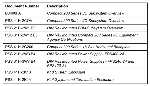
Foxboro ™  DCS FPS480-24 is a 480W compact DC power supply launched by Schneider Electric, belonging to the Foxboro DCS system supporting equipment under the EcoStruxure architecture. Its core function is to provide stable 24V DC power supply for DCS system loads (such as FCP280 controller, Compact/Standard 200 series I/O subsystem equipment), and can also be expanded to power external field devices. Its design is compatible with K13 system enclosures and K14 system and terminal enclosures, supports customized configurations (meeting power consumption and wattage requirements), and has passed ATEX, UL, UL-C certifications. It can be used in Class 1, Division 2 (North America), and Zone 2 (International) hazardous areas, especially suitable for DCS system power supply needs in harsh industrial environments.

Core Features and Advantages

(1) Wide range input and high efficiency

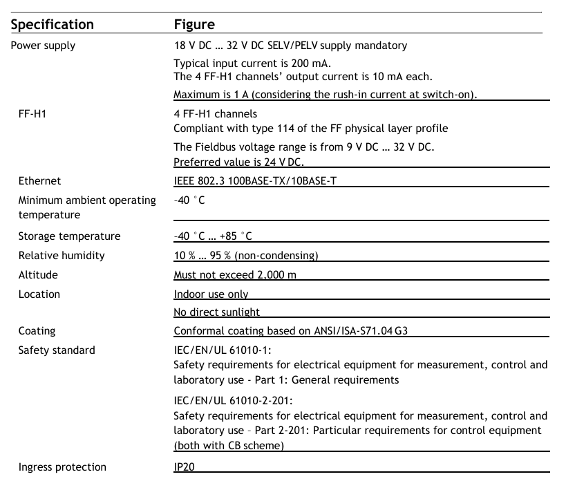
Flexible input adaptation: automatically compatible with alternating current (AC) and direct current (DC) inputs, with an AC input range of 85-264V AC (47-63Hz, single-phase) and a DC input range of 120-264V DC (output reduced to 90% when 108-119V DC), meeting the voltage standards of power grids in different regions around the world without the need for additional transformers.

High efficiency and energy saving: With an efficiency of up to 94% (at 230V AC input), low energy consumption reduces operating costs. Based on average electricity prices and load calculations, the return on investment (ROI) can be less than 2 years; Built in power factor correction (PFC) circuit, with a power factor close to 1 when AC input (0.98 at 115V AC and 0.92 at 230V AC), reducing harmonic interference in the power grid.

(2) Security protection and reliability

Multiple protection mechanisms

Overcurrent protection: dual stage current limitation, automatically shuts down when the load current exceeds 105% of the rated value (at 25 ° C) for more than 4 seconds; The typical value of short-circuit current is 48A, and the output constant current setting value is about 32.5A to avoid short circuit damage to the equipment.

Overvoltage protection: When the output voltage is abnormally high, it will automatically shut down. The input power supply needs to be disconnected (within 30 seconds) to reset, and the power supply will be restored after troubleshooting.

Isolation and Insulation: The insulation resistance between input-output, output casing, and input-output casing is greater than 100M Ω (tested at 500V DC), and the insulation strength meets industrial safety standards to prevent leakage risks.

Environmental adaptability: The shell is coated with a conformal coating to prevent corrosion; The protection level and environmental tolerance meet the G3 level harsh environment standard, supporting working temperatures of -25~70 ° C (load linearly reduced to 75% at 60-70 ° C), relative humidity of 5-95% (no condensation), altitude of -300~3000m (storage altitude up to 12000m), no need for fans, and reducing mechanical failure points through natural convection heat dissipation.

(3) Compliance in hazardous areas

Complete certification: UL/UL-C certification (compliant with UL60950-1 and UL508 standards), ATEX certification (Ex nA IIC T3), IECEx certification, can be used in Class 1, Division 2 (Groups A-D), Zone 2 (IIC explosion group) hazardous areas, as an “associated device” to power non flammable communication circuits (requires coordination with designated processor modules, refer to the DIN Rail Installation Subsystem User Guide).

Technical specifications

(1) Input and output parameters

Category specification details

Input specifications – AC input: 85-264V AC (47-63Hz, single-phase), input current 4.5A at 115V AC, 2.3A at 230V AC

-DC input: 120-264V DC (108-119V DC with 90% derating), input current 4.5A

-Starting voltage: typical value 71.6V AC, shutdown voltage: typical value 66.7 V AC

Output specification – Output voltage: 24.0V DC (factory set ± 0.2V DC)

-Voltage regulation rate: Line regulation rate 96mV, load regulation rate 240mV

-Output current: rated 20A (480W), maintained at 20A at 60 ° C, reduced to 15A (360W) at 70 ° C

-Ripple and noise: typical value of 240mVpp, maximum value of 600mV (at -25~0 ° C)

-Temperature coefficient:<0.02%/° C

-Soft start time:<1 second (115V AC input)

-Holding time: 14ms (full power, 115/230V AC input)

(2) Physical and installation specifications

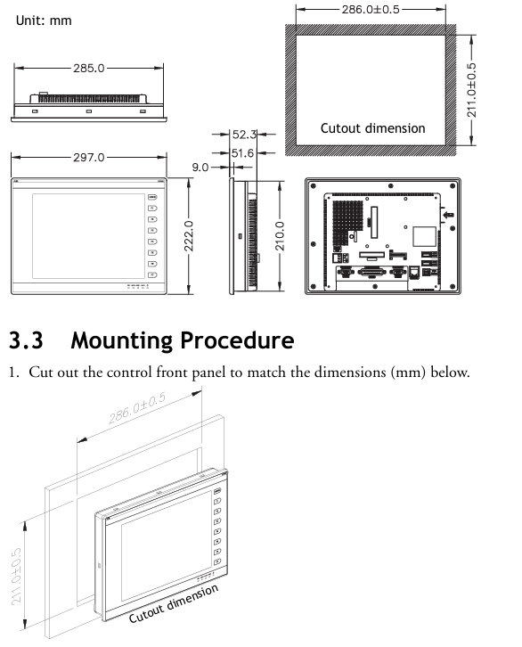
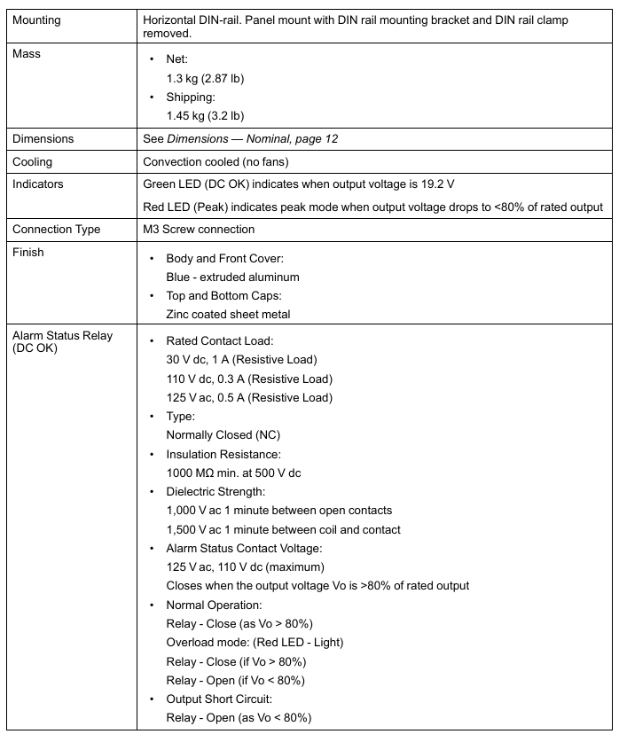
Installation method: Horizontal DIN rail installation (standard DIN rail bracket and fixture), detachable bracket supports panel installation.

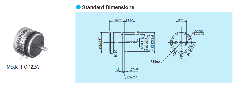
Dimensions and Weight: The nominal dimensions are approximately 123mm (length) x 88mm (width) x 82mm (height), with a net weight of 1.3kg (2.87lb) and a gross weight of 1.45kg (3.2lb). The compact design saves cabinet space.

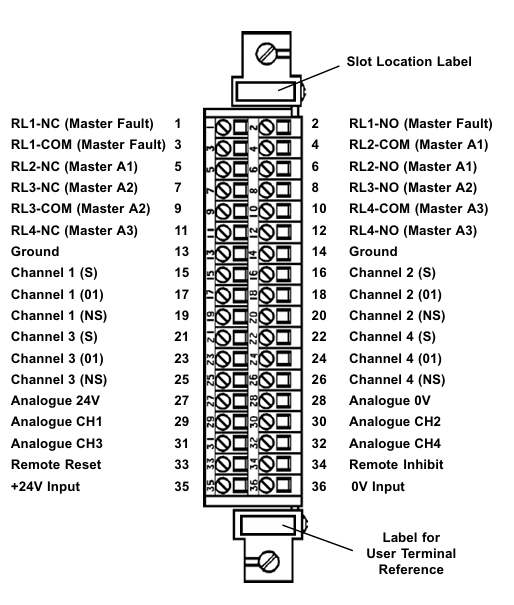
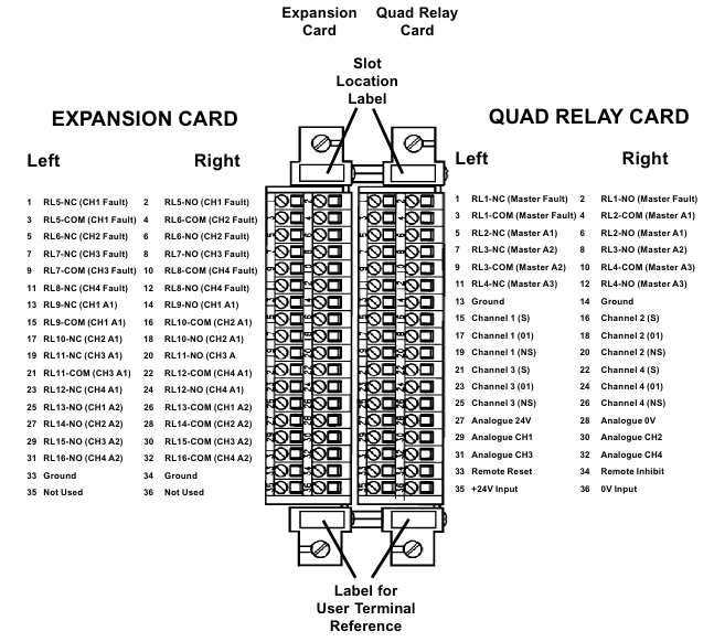
Connection method: M3 screw terminal connection, input and output cables need to be provided by the user. It is recommended to use 14AWG (high current circuit) or 18AWG (low current circuit) wires.

(3) Status monitoring and alarm

LED indication: Green “DC OK” LED indicates output voltage>19.2V (normal operation); The red “Peak” LED indicates that the output voltage is less than 80% of the rated value (under voltage or overload).

Relay alarm: The “DC OK” normally closed (NC) relay contacts close when the output voltage is greater than 80% of the rated value, and disconnect when it is less than 80% (such as short circuit, overload, or no input power). External alarm can be triggered by external modules such as FBM207b. The rated load of the relay contacts is 30V DC/1A, 110V DC/0.3A, 125V AC/0.5A, with insulation strength of 1000V AC (between contacts) and 1500V AC (between coils and contacts).

Environment and Compliance

(1) Environmental tolerance

Environmental indicators, operating range, storage range

Temperature -25~70 ° C (-13~158 ° F), linear load derating at 60-70 ° C -40~70 ° C (-40~158 ° F)

Relative humidity 5-95% (no condensation) 5-95% (no condensation)

Altitude -300~3000m (-1000~10000ft) -300~12000m (-1000~40000ft)

Vibration<19.6m/s ² (2G)-

(2) Electromagnetic Compatibility (EMC) and Safety Certification

EMC compliance: Compliant with IEC/EN 60950, UL60950-1, UL508, Semi F47 (only 200V AC) and other standards, with conducted emission (EN55022-B/CISPR22-B), radiated emission (EN55022-B/CISPR22-B), harmonic current (IEC61000-3-2 Class A) and other indicators meeting standards. Anti interference capabilities include: 8kV contact discharge/15kV air discharge (ESD), 2kV electrical fast transient (EFT), 2kV line to ground/4kV line to neutral lightning surge, 10V conducted RF common mode interference, etc.

Safety certification: UL file number E45026, CSA file number LR35579; ATEX certification (Ex nA IIC T3), CENELEC certification, meeting the requirements for use in hazardous areas; California Proposition 65 Warning: Products containing lead and lead compounds may cause cancer or reproductive harm. For more information, please refer to www.p65warnings. ca.gov.

Accessories and Connection Configuration

(1) Core accessory model

Accessory name, model, and purpose

The RH101CR core power supply unit of the power host provides 24V DC/20A output

AC input terminal block cable -1 cable is required to connect the terminal block to the power host

Connect the power supply to the Compact/Standard 200 series motherboard using RH100DY (3.7m), RH100DZ (0.6m), and RH100EA (1.0m) cables, with 14AWG supporting 20A current

DC distribution component RH101BY is used for multi board connection to achieve power distribution

Bottom board power cable (distribution component to bottom board) RH100EB (2.1m), RH100EC (3.0m) 18AWG, directly connecting the distribution component to the bottom board, supporting up to 2 bottom board direct connections

(2) Connection precautions

If only 1-2 base plates are connected, RH100EB/RH100EC cables can be directly used; If more than 2 baseboards are connected, power must be distributed through the RH101BY distribution component to avoid current overload.

It is recommended to use an independent power supply for external on-site equipment to avoid non system loads affecting the stability of DCS system power supply; All wiring must be fastened with M3 screw terminals to ensure reliable contact.

Key points for use and maintenance

Calibration requirements: The power supply is pre-set with a 24.0V DC output at the factory, which does not require user calibration or voltage adjustment, reducing maintenance workload.

Fault handling: After shutting down due to overvoltage/overcurrent, the input power supply should be disconnected first (within 30 seconds), and load faults (such as short circuits and overloads) should be checked before powering on again to restore power; When the “DC OK” relay is disconnected, it is necessary to check whether the output voltage is less than 80% of the rated value (19.2V DC), and troubleshoot input power supply, load, or internal power supply faults.

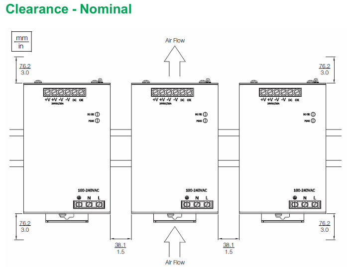
Installation spacing: To ensure natural convection heat dissipation, a ventilation gap of at least 76.2mm (3.0in) should be reserved around the power supply to avoid installation in close proximity to heating equipment.

GE Multilin 469 Motor Protection System

Product positioning and core values

The GE Multilin 469 motor protection system belongs to the SR relay family and is an integrated protection and management device designed specifically for medium and high voltage, large and medium-sized motors. It adopts a pull-out structure, balancing cost-effectiveness and industry-leading flexibility. Its core positioning is to provide comprehensive protection, precise control, simplified configuration, and advanced communication functions for medium and large three-phase motors (including high inertia, dual speed, and step-down starting motors), suitable for safe operation and management of motors and driving equipment in industrial scenarios. It can adapt to different motor characteristics through customized overload curves, single CT differential protection, and other functions. At the same time, with the help of motor parameter auto configurator, multi communication protocol compatibility, and other features, deployment and operation costs can be reduced, and equipment availability can be improved.

Core functions and protective features

(1) Comprehensive motor protection function

Hot model protection (core protection mechanism)

Multidimensional thermal management: integrating six core elements: overload curve (standard/customized/voltage dependent), negative sequence current bias (compensating for additional rotor heating), cold and hot safety stagnation ratio (defining the steady-state thermal capacity utilization rate of the motor), cooling time constant (distinguishing the heat dissipation rate during operation/shutdown), startup suppression and emergency restart (preventing startup when the thermal capacity is insufficient), RTD bias (combined with stator RTD temperature correction thermal model), updating the thermal capacity utilization rate (TCU) every 0.1 seconds, accurately simulating the actual thermal state of the motor.

Overload Curve Characteristics: Provides 15 standard overload curves (multiplier 1-15). The voltage dependent curve is suitable for high inertia loads and can dynamically adjust the thermal overload curve during the acceleration phase according to the system voltage, avoiding motor overheating caused by acceleration time exceeding the safe dead time.

Fault and abnormal working condition protection

Electrical fault protection: covering stator differential protection (supporting 6 CT external summation or 3 flux balanced CT connection, distinguishing the tripping threshold for startup/operation status), short circuit protection (removing the DC component of fault current, supporting secondary tripping backup when the fault is not cleared), grounding fault protection (supporting zero sequence CT, high sensitivity CT, phase CT residual connection, dual tripping/alarm threshold).

Abnormal working condition protection: including mechanical jamming (detecting rotor stalling, locking during startup), acceleration time monitoring (preventing abnormal long acceleration process), undervoltage/overvoltage (independent threshold during motor startup/operation phase, supporting locking in case of VT fuse failure), underfrequency (adjustable from 20-60Hz), over torque (adjustable from 1.0-999999.9 Nm/ft lb, only induction motor alarm), current imbalance (detecting negative sequence current ratio, including phase failure detection algorithm, dual trip/alarm threshold), etc.

Temperature and hardware protection

RTD Temperature Monitoring: Supports 12 programmable RTD inputs (compatible with Platinum 100, Nickel 100/120, Copper 10, etc.) to monitor stator, bearing, and ambient temperature. Each RTD includes three levels of thresholds: alarm, high alarm, and trip. Supports RTD trip voting and open/short circuit fault alarm.

Other hardware protections: including reverse power (to prevent motor from generating electricity due to reverse dragging), underpower (to detect load loss), abnormal power factor (synchronous motor out of step detection), limit on starting times/starting intervals (to prevent excessive starting losses), etc.

(2) Control and configuration functions

Flexible control mode: supports dual speed motor protection (independent overload curve), voltage reduction start monitoring (transition current/time control), frequency conversion filtering (suitable for accurate acquisition of analog signals in VFD scenarios), analog input differential calculation (dual drive system application), trip coil monitoring, etc., to meet the control requirements of different starting modes and operating scenarios.

Simplified configuration tool: equipped with a motor parameter auto configurator, complete parameter settings through a 6-step guided operation; Support on-site firmware and parameter upgrades, with optional conformal coatings for chemical corrosion/humid environments to enhance equipment adaptability.

Monitoring, measurement, and diagnostic capabilities

(1) High precision measurement function

Electrical parameter measurement: Real time monitoring of phase current, differential current, grounding current, average current, current imbalance, phase voltage/line voltage, average voltage, frequency, as well as active/reactive/apparent power, power factor, electrical energy (Wh/var), torque, demand value, etc., with measurement accuracy of ± 0.5% (when current<2 times CT) and ± 1% (when current>2 times CT).

Non electrical parameter measurement: 12 channel RTD temperature (range -50~250 ℃, accuracy ± 2 ℃), motor speed (100-7200 RPM, supporting inductive/Hall sensors), analog input (4-20mA/0-20mA/0-1mA, accuracy ± 1% of full range).

(2) Data recording and diagnosis

Event Recorder: Timestamp records system events, storing up to 256 events for easy tracing of fault causes.

Waveform capture: Record 10 waveforms (Ia/Ib/Ic/IG/Diffa/Diffb/Diffc/Va/Vb/Vc) during tripping, with 12 samples per cycle and a total of 64 cycles of data, supporting fault waveform analysis.

Advanced diagnosis: optional rotor bar breakage detection function, continuously monitoring the health status of the rotor through motor current signal analysis (MCSA), early warning of rotor faults (such as starting torque drop, overload, bearing wear), supporting programmable alarms, and achieving predictive maintenance.

Simulation testing: Pre trip and fault conditions (current, voltage, frequency, RTD temperature, etc.) can be simulated without external input, simplifying the debugging and commissioning process.

Hardware specifications and interface configuration

(1) Input/output interface

Current and voltage input

Current input: 2 sets of three-phase CT inputs (phase current CT supports 1A/5A secondary side, specified when ordering; Differential CT field programmable 1A/5A), 2-channel grounded CT input (standard CT supports 1A/5A, high-sensitivity CT supports 50:0.025A), CT withstand capability up to 80 times rated current for 1 second, 40 times rated current for 2 seconds, and 3 times rated current for continuous operation.

Voltage input: Three phase VT input (supporting star/delta connections, full range 273V AC, accuracy ± 0.5% full range, frequency range 20-120Hz), supporting VT fuse fault detection.

Digital and Analog Interface

Digital input: 9-way optically isolated input (5 pre-defined: starter status, emergency restart, remote reset, parameter access, test switch; 4 assignable: remote trip/alarm, speed switch, vibration switch, pressure switch, etc.), supports dry contact or NPN collector input.

Analog input/output: 4-channel configurable analog input (supports 4-20mA/0-20mA/0-1mA, input impedance 226 Ω± 10%), 4-channel configurable analog output (specify 4-20mA or 0-1mA when ordering, accuracy ± 1% of full scale, 4-20mA maximum load 1200 Ω, 0-1mA maximum load 10k Ω).

Output relays: 6 sets of Form-C output relays (4 sets of non fault safe type, can be assigned with trip/alarm function; 1 set of non fault safe type start interlock relay; 1 set of fault safe type service relay, indicating loss of control power or internal fault), supporting interlock function, with a maximum rated contact value of 10A continuous (DC 30V 300W, AC 250V 2770VA).

(2) Human Computer Interaction and Communication

Local interaction: 40 character display screen (displaying parameters, actual values, fault/alarm information), numeric keypad (parameter input and navigation), 22 LED indicator lights (system status, motor status, output relay status), supporting 20 user-defined default messages.

Communication capability: Comes standard with 3 serial ports (front RS232 for debugging, rear 2 RS485 for remote communication), optional 10BaseT Ethernet and DeviceNet ports; Supports Modbus RTU (serial port) and Modbus TCP/IP (Ethernet port), multiple ports can communicate simultaneously, and Ethernet can be connected to local/wide area networks, replacing multi drop wired networks and reducing operation and maintenance costs.

Software and Operations Support

(1) EnerVista software suite

Configuration and Debugging Tools: Provides automatic configuration of motor parameters, firmware upgrades, parameter backup/recovery functions, supports waveform and event viewing, and simplifies fault diagnosis.

Monitoring and integration tools: Viewpoint Monitoring provides plug and play device monitoring, single line diagram monitoring and control, alarm annunitor, trend reports; EnerVista integrator includes OPC/DDE servers, Multilin drivers, and supports seamless integration with existing HMI/SCADA systems.

Maintenance tool: Viewpoint Maintenance provides parameter audit tracking reports, equipment health reports, and comprehensive fault diagnosis to enhance operational security and efficiency.

(2) Pull out structure and retrofit support

Pull out design: easy to replace quickly, reduces downtime, supports wire lead sealing to prevent unauthorized removal.

Retrofit upgrade: With the 8 series Retrofit kit, old SR 469 relays can be upgraded to 869 motor protection systems without modifying existing panel openings, rewiring, or changing drawings. The upgrade process only requires 3 steps (updating parameter files, removing old relays, plug-in reconnection) and can be completed in as fast as 21 minutes, reducing upgrade costs and system downtime.

Technical specifications and environmental adaptability

(1) Key technical parameters

Category specification details

Current measurement CT primary side 1-5000A, secondary side 1A/5A; Accuracy: ± 0.5% for current<2 times CT, ± 1% for current>2 times CT

Voltage measurement VT ratio 1.00-15.00:1, secondary side full range 273V AC; Accuracy ± 0.5% of full scale

RTD measurement supports 4 types of RTD, with a range of -50~250 ℃ and an accuracy of ± 2 ℃. Each channel has a 3-level threshold (alarm/high alarm/trip)

Communication speed serial port baud rate 300-19200 bps, Ethernet 10Mbps

Low range of power supply: DC 24-60V/AC 20-48V; High range: DC 90-300V/AC 70-265V, power 45VA (maximum)

(2) Environment and Compliance

Environmental adaptability: working temperature -40~+60 ℃, storage/transportation temperature -40~+80 ℃, humidity 0-95% (55 ℃ without condensation), protection level IP40 (front)/IP20 (back), pollution level 2.

Compliance certification: Compliant with EN60255 series, IEC 61000 series, UL508/UL1053, cULus and other standards, passed ISO9001 quality system certification, CE certification (EN60255-5/27, EN61010-1, etc.).

Ordering and configuration options

(1) Basic models and core options

Basic unit: The model starts with “469”, and subsequent codes distinguish key configurations:

CT secondary side: P1 (1A), P5 (5A);

Control power supply: LO (low range: DC24-60V/AC20-48V), HI (high range: DC90-300V/AC70-265V);

Analog output: A1 (0-1mA), A20 (4-20mA);

Extended functions: D (DeviceNet), E (Enhanced Front Panel), T (Enhanced Front Panel+Ethernet), H (Anti harsh Environment Coating).

(2) Optional accessories

Including pull-out handle (with lead seal), RTD sensor, CT/VT of different specifications, Retrofit upgrade kit (including terminal block and depth reduction ring compatible with old SR relays), EnerVista software kit, etc., can be flexibly selected according to on-site needs.

image.png

Honeywell System 57 5704 Control System

Product positioning and core functions

The Honeywell System 57 5704 control system is a microprocessor controlled device used for industrial gas detection, belonging to the System 57 product family. Its core function is to monitor industrial gas detectors installed on site, achieve multi-channel gas concentration monitoring, alarm triggering, and system management. It is suitable for indoor non hazardous areas and should not be exposed to rainwater or moisture. It is also not designed for use in hazardous areas. The system supports catalytic and 4-20mA input types of gas sensors, with flexible alarm configuration, remote control, and self diagnostic capabilities. Calibration, maintenance, and parameter settings can be performed through engineering cards, and it is also compatible with extended functions such as Modbus communication and event printing.

System composition and hardware specifications

(1) Core hardware module

Four Channel Control Card

Type differentiation: divided into catalytic input type (model 05704-A-0144) and 4-20mA input type (model 05704-A-0145). The former supports catalytic gas sensors and provides constant current drive (adjustable from 90-315mA), while the latter is suitable for 4-20mA circuit power supply sensors with a measurement range of 0-25mA.

Display and indication: Equipped with four LCD displays (25 segment analog bar, 4-digit digital display, 4-digit message display, icon area), 4 channel LEDs (CHL1-CHL4) and 1 Attention (ATTN) LED, which can distinguish A1/A2/A3 alarm, STEL/LTEL alarm, fault, suppression and other states by LED flashing frequency/color.

Core parameters: Initial accuracy ± 1%, alarm set point resolution 1% of full range, electronic drift<± 3%/6 months, operating voltage 18-32V DC, catalytic type maximum power consumption 12.8W, 4-20mA type maximum power consumption 8.3W.

relay interface module

Quad Relay Interface Card (model 05704-A-0121): Provides 4 Single Pole Double Throw (SPCO) relays, supporting latch/non latch, power on/off action modes, and rated relay contacts 5A@110 /250V AC or 32V DC, supporting interface connection between sensors and control cards, with a maximum power consumption of 1.7W.

Relay Interface Assembly (model 05704-A-0131): It consists of four relay interface cards and an extended relay card, including 12 SPCO relays and 4 Single Pole Single Throw (SPST) relays, occupying 2 card slots, with a maximum power consumption of 6.5W, suitable for scenarios that require more relay outputs.

Engineering Card (Model 05701-A-0361)

Functional positioning: The core module for system configuration, calibration, and maintenance, equipped with green power LED, red unlock LED, as well as directional keys (up/down), confirm/cancel keys, function keys (BEAD mA, ALARMS, ZERO, SPAN, etc.).

Core Capability: Supports sensor bridge current regulation, alarm threshold setting and relay testing, zero/range calibration, system clock setting, can be configured and data printed through RS232 interface connected to printer or PC, with a power consumption of approximately 1.5W.

DC Input Card (Model 05701-A-0325)

Function: Provides a system DC power supply interface, supports two independent power inputs (such as main power and backup battery), has diode isolation and 10A anti surge fuse, supports 2.5mm ² (14 AWG) wire terminals, and operates at a voltage of 18-32V DC.

other modules

Analog output module: divided into current absorption type (04200-A-0145) and current source type (04200-A-0146), output range 0-20mA or 4-20mA software optional, linearity ± 2% of full range, supporting external power supply of 18-40V.

Expansion module: including event printing module (05701-A-0314), Modbus interface module (RS232 type 05701-A-0313, RS485/422 type 05701-A-0312), alarm update module (05701-A-0309), etc., used to expand communication and alarm functions.

(2) System rack and cabinet

Rack: available in full 19 inch and half 19 inch widths, supporting front or rear wiring, including engineering cards, DC input cards, and interconnecting cables (front wiring type), made of galvanized steel, with M5 grounding terminal bolts, weighing approximately 287.6-217.6g including modules (depending on model).

Cabinet: divided into 8 channels (model 05701-A-0452) and 16 channels (model 05701-A-0451), made of low carbon steel, RAL 7015 dark gray, equipped with knockout cable sealing sleeves (8 channels include 2 M25, 8 M20, etc.), weighing 10kg for 8 channels and 13.5kg for 16 channels.

(3) Power supply unit

AC-DC power supply unit: divided into 8 channels (model 05701-A-0406) and 16 channels (model 05701-A-0405), input 85-264V AC (47-440Hz) or 110-340V DC, output 24V DC ± 10%, can be upgraded by adding a 50W switch module (model 05701-A-0440) (maximum 100W for 8 channels, maximum 200W for 16 channels), with overload protection (triggered by 105% rated load, automatic recovery), maximum leakage current 0.75mA/50W module.

Installation and wiring requirements

(1) Environment and Location

For indoor use only, avoid heat sources, moisture, and physical damage. The ambient temperature is -5-55 ℃ (ATEX certification system is 0-55 ℃), the humidity is 0-90% RH (no condensation), and the altitude is ≤ 2000m.

The installation of sensors should follow the characteristics of gas density (installation height for gas sensors lighter than air, installation height for sensors heavier than air), avoid areas where airflow is obstructed, quiet corners, and near heat sources, and be easy to maintain.

(2) Wiring and Connection

Sensor wiring: It is necessary to use cables with grounding and external shielding to avoid parallel interference sources such as AC power lines and motors. The maximum length of the cable depends on the type of sensor and the cross-sectional area of the wire (for example, when using 2.5mm ² wire for catalytic sensors, the maximum length is 2500m, and when using 2.5mm ² wire for 4-20mA sensors, the maximum length is 16000m). The shielding layer is only grounded at the cabinet end.

Power and relay wiring: The rated current of the power cable should be greater than the maximum load. If the relay cable is connected to an AC power source, a 5A fuse is required. The DC input card and relay interface card terminals support 2.5mm ² wires. When wiring, the power should be disconnected to avoid short circuits.

(3) Power configuration

The total power consumption of the system needs to be calculated through the “power budget table”, depending on the sensor type, number of channels, and module configuration; When there are more than 8 catalytic control cards, it is recommended to supply power separately through the four relay interface card to avoid the backplane current exceeding the 8A limit.

Supports dual input of main power supply and backup battery, with diode isolation achieved through a DC input card. The backup battery needs to be compatible with 18-32V DC specifications.

Operation and maintenance process

(1) Basic operation (without engineering key)

Control card reset and selection: Short press the RESET/SET button to reset inactive alarms and clear peak display; Long press and hold for 1.5 seconds to select the control card, then use the up and down keys on the engineering card to select the channel; Press and hold for 5 seconds to perform an extended reset (clear maximum/minimum readings, reset STEL/LTEL timer).

Basic functions of the engineering card: It can view the catalytic sensor bridge current (BEAD mA key), alarm threshold (ALARMS key), sensor signal (SIGNAL key), and system clock (CLOCK key). Calibration, suppression, and other operations cannot be performed without a key, and the selection will be automatically canceled after 30 seconds of timeout.

(2) Engineering operation (requires inserting the engineering key to unlock)

Channel suppression (INHIBIT key): After selecting a channel, press the INHIBIT key to switch the suppression state. During suppression, the channel LED will remain amber and the relay will be locked in an inactive state to avoid false alarms during calibration or troubleshooting.

Calibration process

Zero calibration (ZERO key): Ensure that the sensor is in a gas free environment, press the ZERO key, wait for the signal to stabilize (message displays “STANBLE”), and then press the confirm key. The system will automatically set the current signal to zero. If the signal exceeds the range, an error will be displayed.

Range calibration (SPAN key): Suitable for calibrated sensors, press the SPAN key to set the target range concentration, introduce the corresponding concentration standard gas, confirm after the signal is stable, and the system updates the range parameters; The new sensor requires the “1st SPAN” key to perform the first range calibration and record the initial sensitivity for lifespan monitoring.

Alarm and Relay Testing: Press the ALARMS key to set the A1/A2/A3/SETL/LTEL threshold. After switching to “TEST” mode, simulate gas concentration changes by pressing the up and down keys to verify whether the alarm LED and relay actions are normal. During testing, be sure to release the suppression to trigger the external relay.

(3) Maintenance and troubleshooting

Regular maintenance: It is recommended to check the terminal fastening, LED status, sensor signal and alarm function every year. The catalytic sensor needs to be calibrated regularly (according to the sensor manual). When the sensitivity of the catalytic sensor drops below 50% of the initial value, the system displays “Lifetime Expired” and the sensor needs to be replaced.

Fault diagnosis: Identify the problem through the error codes displayed on the control card message (such as ER97 for EEPROM fault, ER87 for over range fault, ER83 for bridge current fault), and check the power supply, wiring, and sensor status using the “troubleshooting table”. Hardware faults require replacement of the corresponding module.

Data recording: It can be connected to an RS232 printer through an engineering card, and long press the up and down keys to print single channel status or overall rack summary data, including sensor type, calibration date, alarm threshold, relay configuration, and other information.

Compliance and safety requirements

(1) Certification and Standards

Compliant with EN50054/57/58 (General Requirements and Performance for Combustible Gas Detection), EN50271 (Software and Digital Technology), EMC Directive 89/336/EEC (EN50270:1999), Low Voltage Directive 73/23/EEC (EN 61010-1), ATEX certification based on EC Type Examination Certificate BVS 04 ATEX G 001 X, suitable for Zone 2 hazardous areas (requiring tested enclosures).

(2) Safety operation standards

Installation and maintenance should be carried out by professionals, and wiring should be operated after power failure to avoid equipment damage caused by incorrect sensor wiring; When used in hazardous areas, it is necessary to comply with the installation standard EN 60079-14 to ensure the enclosure protection level and explosion-proof requirements; The data read by Modbus is only used for visualization or recording and cannot be used for safety related control to avoid Modbus write operations.

Ordering and Accessories

Core module ordering models: Control card, relay interface card, engineering card, DC input card, etc. The core module models are clear, and the power unit, cabinet, and rack need to be selected according to the number of channels and installation requirements (such as 8-channel cabinet 05701-A-0452, 16 channel power supply 05701-A-0405).

Optional attachments: including blank panel (05701-A-0365), engineering key kit (05701-A-0550), interconnect cable (05704-C-0160), liquid tight connector kit, etc. Expansion modules such as Modbus interface and event printing module need to be ordered separately.

Sakae toshin FCPS22AC, FCP22A, FCP30A series potentiometers

Overall positioning and common features of the product

The FCPS22AC, FCP22A, and FCP30A series launched by Sakae toshin are all single turn conductive plastic servo installed potentiometers, which are core compatible with precision and stability requirements for speed and voltage regulation in industrial control, automation equipment, and other scenarios. They all comply with RoHS environmental standards and have common advantages such as “oil-free metal bearings (some models)”, “infinite resolution”, and “low contact resistance variation”. The mechanical stroke is 360 ° unrestricted rotation, suitable for continuous adjustment scenarios.

Comparison of core parameters of various models

(1) Differences in basic specifications and dimensions

Model size characteristics (key dimensions, unit: mm) Weight Bearing type Power rating

FCPS22AC overall dimensions: 20 (length) x 11.5 (width) x 8.2 (height), mounting hole: 2 x M2 (depth 5), shaft related dimensions: 1.57 ± 0.2 (two locations), maximum 0.8 (shaft diameter related), approximately 20g oil-free metal bearing 1.0W

FCP22A overall dimensions: 15 (length) × 11.5 (width) × 12 ± 0.2 (height), mounting hole: 2 × M2 (depth 4), outer diameter: φ 22.23 (+0.13/-0.25), φ 19.05/φ 19.1, arc radius R18MAX about 15g unspecified (default servo installation adaptation structure) 1.0W

FCP30A overall dimensions: 15 (length) × 11.5 (width) × 15 ± 0.2 (height), mounting hole: M3 (depth 4), outer diameter: φ 26.97 (+0.13/-0.25), φ 27 ± 1/φ 24, arc radius R20MAX about 25g not clearly marked (default servo installation adaptation structure) 1.5W

(2) Differences in electrical performance

Performance indicators FCPS22AC FCP22A FCP30A

Standard resistance values 1k, 2k, 5k, 10k Ω 1k, 2k, 5k, 10k Ω 1k, 2k, 5k, 10k Ω

Special resistance values 500, 20k, 50k, 100k Ω 500, 20k, 50k, 100k Ω 500, 20k, 50k, 100k Ω

Total resistance tolerance standard level ± 15% (L), precision level ± 10% (K) standard level ± 10% (K) standard level ± 10% (K)

Independent linear tolerance standard grade ± 1.0%, precision grade ± 0.5% standard grade ± 1.0%, precision grade ± 0.5%, ultra precision grade ± 0.25% standard grade ± 1.0%, precision grade ± 0.5%, ultra precision grade ± 0.2%

Electrical stroke 320 °± 5 ° 320 °± 5 ° 340 °± 5 ° (longest stroke, wider adjustment range)

Insulation resistance>1000M Ω at 500V DC>1000M Ω at 1000V DC (stronger insulation performance)>1000M Ω at 1000V DC (stronger insulation performance)

Dielectric strength: withstand for 1 minute at 500V AC, withstand for 1 minute at 1000V AC (stronger resistance to voltage breakdown), withstand for 1 minute at 1000V AC (stronger resistance to voltage breakdown)

Starting torque ≤ 5mN · m (50gf · cm) ≤ 1.5mN · m (15gf · cm) (minimum torque, smoother adjustment) ≤ 2mN · m (20Gf · cm)

Temperature coefficient of resistance ± 400p.p.m./℃± 400p.p.m./℃± 400p.p.m./℃

Common Special Specification Options (applicable to the entire series)

Each model supports customized specifications to meet specific scenario requirements, mainly including:

Extra tap: Supports up to 1 tap, suitable for multi gear fixed voltage/resistance output requirements.

Axis extension design: Front and rear axis extension (default diameter of 3mm for rear axle, 10mm for FCPS22A/FCP30A, 20mm for FCPS22AC), suitable for connection requirements in special installation spaces.

Limiting device: After installation, the rotation angle is limited to 320 °, and the limiting strength is 0.9N · m (9kgf · cm) for FCPS22AC and 0.3N · m (3kgf · cm) for FCP22A/FCP30A, to prevent equipment damage caused by excessive rotation.

Special electrical stroke: Non standard electrical stroke can be customized according to requirements (default 320 °± 5 ° or 340 °± 5 °).

Shaft diameter and processing: Supports special shaft diameters (such as British size of φ 3.175mm, φ 6.35mm) and special processing of shaft bodies (such as slotting, rolling, etc.).

Multi link structure: FCP22A/FCP30A supports up to 5 link structures, with an increase in shell length of 8.5mm for each additional link, suitable for multi-channel synchronous adjustment scenarios.

Precautions

Customized specification impact: If special specifications are selected (such as multi link, special shaft, customized stroke), the general specifications of the potentiometer (such as insulation resistance, torque) and environmental adaptability may change, and it is necessary to communicate and confirm with the manufacturer in advance.

Installation and use: The appropriate screws should be selected according to the installation hole size of each model (such as 2 × M2 for FCPS22AC and M3 for FCP30A) to avoid over tightening and damaging the housing; When making electrical connections, it is necessary to match the power rating (such as FCP30A maximum 1.5W) to prevent overload and burnout.

Environmental adaptation: The waterproof and dustproof levels are not clearly marked, and it is assumed to be suitable for dry, non corrosive indoor industrial environments. Additional protection is required for harsh environments.

ABB LD 810HSE Ex Foundation fieldbus connection equipment

Core positioning and basic attributes of the product

(1) Product identity and functional positioning

ABB LD 810HSE Ex is a foundation fieldbus ™  Fieldbus connects devices and is registered as a 42c class device according to the HSE protocol specification. Its core function is to serve as a gateway between the FF high-speed Ethernet (FF-HSE) subnet and the FF-H1 link, enabling data exchange and device management between different bus types. It also supports device redundancy and ensures communication stability in industrial control scenarios.

(2) Physical and installation characteristics

Protection level: IP20, only suitable for indoor environments, must avoid direct sunlight, and has no impact protection or IP54 protection capability. When installed in hazardous areas, it must be equipped with a protective shell that meets the requirements of IEC/EN 60079-0 Section 26.4 (with impact resistance and corresponding IP level).

Installation method: DIN rail installation, suitable for standardized installation scenarios inside industrial control cabinets.

Power supply requirements: 24V DC power supply is required (power supply range 18V DC -32V DC, and must be SELV/PELV power supply), with a typical input current of 200mA, 4 FF-H1 channels each with an output current of 10mA, and a maximum current of 1A (including startup surge current).

Core functions and communication capabilities

(1) Gateway core functions

H1 Link Management: Supports up to 4 independent FF-H1 links, and devices in each link can act as Link Masters and SM Time Publishers, responsible for identifying devices connected to the H1 link, configuring system and network management for H1 devices through HSE, and accessing the functional blocks of H1 devices.

Data forwarding and alarm distribution: Implement process data forwarding between H1 links, bidirectional process data forwarding between H1 and HSE subnets, and distribution of alarms and events sent by H1 devices to ensure efficient flow of industrial process data between different bus levels.

HSE side management function: integrates System Management Agent, Network Management Agent, and FMS server (providing H1 device object access capability), supports Simple Network Time Protocol (SNTP) servers based on HSE specifications (for SM time synchronization), but does not support Simple Network Management Protocol (SNMP); Maintenance functions can be implemented through a web server, including firmware updates for connecting devices and H1 power modules (supporting http/https protocol).

(2) Communication performance and limitations

1. Maximum limit on HSE side

Indicator values

64 HSE sessions have been configured

400 HSE virtual communication relationships (VCRs) have been configured

Automatic HSE session count 32

128 automatic HSE virtual communication relationships (VCRs)

H1-H1 data forwarding count 64

2. Maximum limit for a single H1 channel

Explanation of Indicator Values

The total number of VCRs (VCRs) for source/sink, client/server, and publisher/subscriber types in a single H1 channel must not exceed 128

Number of overnight connections (alarm reception) 10-

Number of clients+servers 39+1-

100 publishers and subscribers-

LAS scheduling table number 2-

Number of sub scheduling tables 4-

The number of sequences in each sub schedule table is 64-

The number of elements in each sequence is 4-

LAS scheduling table field size 2000 bytes-

3. Other communication characteristics

H1 Link: Supports H1 Live List, which records device node addresses, PD tags, and device IDs; supports access to H1 port MIB (Management Information Base), but restricts write permissions on the H1 network side; The FF-H1 physical layer complies with Class 114 specifications, with a fieldbus voltage range of 9V DC to 32V DC (recommended 24V DC).

Ethernet: Compatible with IEEE 802.3 standard, supporting speeds of 10Mbit/s or 100Mbit/s, meeting the communication needs of industrial Ethernet.

Applicability and Compliance of Hazardous Areas

(1) Dangerous Area Certification and Applicable Scenarios

1. North American Certification (cULus)

If the device label indicates relevant information, it can be used for Class 1, Division 2, A/B/C/D hazardous areas, or non hazardous areas.

2. European and international certifications (ATEX, IECEx)

Applicable standards: evaluated according to IEC 60079-0:2011 (revised 6, including 2012/2013 revisions), IEC 60079-11:2011 (revised 6, including 2012 revisions), IEC 60079-15:2010 (revised 4), and corresponding EN standards.

Applicable to hazardous areas: If the equipment label or technical documentation indicates relevant information, it can be used in Zone 2 gas explosion environments with IIA/IIB/IIC explosion groups and T4 temperature levels when paired with tested enclosures.

Explosion proof marking: IECEx marking is “Ex nA [ic] IIC T4 Gc”, ATEX marking is “II3G nA [ic] IIC T4 Gc”, where the “[ic]” explosion-proof method is only applicable to the FF-H1 fieldbus interface; Comply with the requirements of Directive 2014/34/EU and strictly follow the hazardous area system installation standards such as IEC/EN 60079-14 during installation.

(2) Other Compliance

Safety standards: Compliant with IEC/EN/UL 61010-1 (Safety Requirements for Electrical Equipment for Measurement, Control, and Laboratory Use – Part 1: General Requirements) and IEC/EN/UL 61010-2-201 (Part 2-201: Special Requirements for Control Systems), and certified by the CB system.

Coating standard: The conformal coating complies with ANSI/ISA-S71.04 G3 standard, enhancing the equipment’s ability to resist environmental interference.

System integration and environmental adaptability

(1) ABB Ability ™  IT system integration

Typical integration architecture: In the ABB 800xA system, the Foundation fieldbus subsystem is connected to the control system through the HSE subnet, and LD 810HSE Ex serves as the gateway between the H1 link field equipment and the HSE subnet; The AC 800M controller interacts with the HSE subnet through the communication interface module CI860 (as the HSE host), and the engineering workstation (Control Builder M), operation and maintenance workstation, etc. access fieldbus data through FF connection servers (with OPC servers).

Redundancy integration: Supports LD 810HSE Ex device redundancy, where the corresponding H1 ports of redundant devices are connected to the same H1 link, and redundant control information is exchanged through redundant link wiring to enhance system reliability; The periodic process data on the H1 link can be forwarded to the HSE subnet through HSE, enabling periodic communication between different H1 link devices and HSE subnet devices. At the same time, H1 device alarms and events can be uploaded to the FF connection server and integrated into the 800xA system alarm management system.

(2) Environmental adaptation parameters

Scope of environmental indicators

Working temperature -40 ° C -+70 ° C

Storage temperature -40 ° C -+85 ° C

Relative humidity 10% -95% (non condensing)

Altitude not exceeding 2000m

Schneider TSXCUSBFIP USB gateway (Fipway/Fipio bus)

Product Core Information

(1) Basic positioning

Product series: Magelis XBT series, belongs to communication accessories, specifically USB gateway, mainly used for terminal devices, supports Fipio and Fipway bus types, can realize communication connection between USB interface of related devices and Fipway/Fipio bus.

Inventory status: Non Stock, usually not regularly stocked in distribution facilities. When purchasing, attention should be paid to the supply cycle.

(2) Key performance parameters

Transmission rate: 12 messages/second (12 messages/s), which specifies the efficiency of data transmission between the bus and USB interface, suitable for industrial control scenarios with moderate communication speed requirements.

Product compatibility: It is compatible with XBTGK, XBTGT, and XBTGTW terminal devices under the Magelis XBT series, ensuring stable communication functionality in specific device combinations. When selecting, it is necessary to match the corresponding compatible models.

Ordering and Logistics Details

Category specific information

Product Classification Code 18225- PLC Network Hardware and PROWORX Software (18225- PLC NTWRK HRDWR&PROWORX SOFT)

Discount Plan PC41, which allows for corresponding discount policies during procurement

Global Trade Item Code (GTIN) 003595863964301, used for product identification and global trade circulation management

Number of packaging units: 1 unit per package (Nbr. of units in pkg.: 1), specifying the quantity of products per package

The packaging weight is 6.61 pounds (approximately 3.0 kilograms), which facilitates weight calculation and packaging planning in the logistics transportation process

Returnability: N, usually cannot be returned after purchase, and careful confirmation of purchasing needs is necessary

The country of origin, France (FR), reflects the production source of the product and may affect procurement related factors such as tariffs and delivery cycles

Installation precautions

First, the importance of industrial equipment installation

In modern industrial production, various equipment and machines are widely used in various fields, such as manufacturing, energy industry, chemical industry and so on. The installation of industrial equipment is directly related to production efficiency and product quality. Proper installation and commissioning of good equipment can ensure the stable operation of the production line, improve production efficiency and product quality, reduce maintenance costs, and ensure the safety of employees.

Second, the steps of industrial equipment installation

1. Preparation: Before the installation of industrial equipment, it is necessary to carry out adequate preparation work. This includes the tools and equipment required for installation, cleaning and preparation of the installation site, and making installation plans and schedules.

2. Determine the installation position: Determine the installation position of the equipment according to the requirements of the equipment and the layout of the production line. When determining the location, the weight and size of the equipment need to be considered, as well as the coordination of the equipment with the surrounding environment.

3. Install the device: Assemble and install the device according to the installation instructions. Ensure that the device is securely and accurately connected, while protecting the appearance and internal components of the device.

4. Connect power supplies and pipelines: For devices that require power supplies and power supplies, properly connect power supplies and pipelines. The connection of power supply and pipeline should comply with safety standards to avoid hazards such as electric shock and leakage.

5. Commissioning the device: After the installation is complete, you need to commission the device to ensure that the device can run properly. It includes checking the functions and performance of the equipment, adjusting the parameters and Settings of the equipment, and carrying out the necessary tests and inspections.

6. Training operators: After the installation of the equipment, it is necessary to train the operators to understand the operation methods and precautions of the equipment, and improve the operation skills and safety awareness of the employees.

Third, industrial equipment installation precautions

1. Safety first: When installing industrial equipment, safety is the most important consideration. You must operate in strict accordance with safety regulations and wear necessary protective equipment to ensure the safety of the workplace.

2. Strictly follow the equipment instructions: Industrial equipment usually comes with detailed installation instructions, you must carefully read and understand the contents of the instructions, and install the operation in accordance with the requirements of the instructions.

3. Pay attention to the assembly sequence: When installing the device, follow the correct assembly sequence to ensure that all components of the device are assembled correctly to avoid equipment failures or safety accidents caused by incorrect assembly sequence.

Applicable Industries

petroleum

Natural gas

chemical industry

cement

metallurgy

ship

mining industry

aviation

transport

Alcoa

machinery

manufacturing

car

KBAC series adjustable frequency drive

Product Overview

The KBAC series adjustable frequency drive is suitable for three-phase AC motors and has a NEMA 4X/IP65 protection level. It can achieve waterproof and dustproof performance and is suitable for indoor and outdoor flushing environments. Supports voltages of 208-230V and 400/460V, with a frequency of 50/60Hz, capable of driving motors ranging from sub fractional horsepower to 10 horsepower. It also has variable speed, soft start function, and electronic motor overload protection. It is compatible with AC inputs of 115V, 208/230V, and 400/460V, and is available in 2G and 3G models. Some 3G models have product labels labeled “(3G)”, and both KBAC-217 and 416 series are 3G models.

Core functions and features

(1) Standard Features

Shell: Industrial grade die cast aluminum shell with hinged cover, available in two surface treatments: dark gray and FDA approved white.

Convenience of operation: No programming required, adjustable potentiometer and jumper settings can be made, and most application scenarios are pre-set at the factory.

Selection function: including motor horsepower selection jumper (J2), switch frequency and GFCI selection jumper (J12, only 3G model), diagnostic LED light (power and status indication), operation/fault relay output contact, start stop switch, barrier terminal block, etc. The driver output frequency can also be selected through jumper to achieve a maximum motor speed of twice the rated speed, with power-off recovery function and zero speed holding torque, as well as multiple adjustable fine adjustment potentiometers.

Jumper selection: covering AC input voltage (only J1 for KBAC-24D and 27D), motor horsepower (J2), automatic power-off recovery/manual start (J3), frequency multiplier (J4), motor frequency (J5), fixed/adjustable boost (J6), regeneration/injection braking (J7), operation/fault output relay operation (J8), normally open/normally closed stop contact (J9), constant torque/variable torque (J10), switching frequency and GFCI (only J12 for 3G models).

(2) Performance characteristics

Power Start ™: Can provide over 200% starting torque to ensure smooth start-up under high friction loads.

Slip compensation: With static automatic tuning and boost function, it achieves excellent load regulation over a wide speed range.

Speed range: The speed ratio can reach 60:1.

(3) Protection features

Motor Overload Protection (I2t): With RMS current limitation, it can prevent motor burnout, avoid false tripping, and is certified by UL as an electronic overload protector for motors.

Electronic Surge Current Limitation (EICL) ™): Eliminate harmful AC input surge currents during startup.

Other protections: equipped with short-circuit protection (shutdown in case of motor phase to phase short circuit), regenerative protection (to avoid tripping caused by high bus voltage due to rapid deceleration of high inertia load), overvoltage and undervoltage protection (shutdown in case of input voltage exceeding the range), MOV input transient suppression (to protect driver components from damage caused by input voltage spikes), and microcontroller self-monitoring and automatic restart functions.

Installation points

(1) Installation method

It is recommended to install it vertically on a flat surface to ensure sufficient ventilation, and reserve enough space below for wiring. If installed inside the casing, it is necessary to ensure that the casing size is sufficient for heat dissipation, the ambient temperature does not exceed 40 ° C (104 ° F), and it cannot be used in explosion-proof environments. The installation must be firm.

(2) Communication input circuit breaker

The driver does not have a built-in circuit fuse, and a fuse (such as Littelfuse 312/314, Bus ABC, or equivalent) or circuit breaker must be connected in series with each non grounded wire according to electrical specifications. The neutral wire or grounding wire should not be blown. Please refer to Table 2 (page 7) for specific fuse specifications.

(3) Electrical connection

Wiring specifications: It must comply with the National Electrical Code and applicable local regulations. Wiring should be carried out after power failure to ensure correct grounding. When remotely connecting potentiometers, switches, etc., it is recommended to install signal isolators to avoid high voltage risks.

Communication input connection: The wiring terminals of different models of drivers are different, and they need to be connected according to the model. The rated AC input voltage of the driver needs to match the actual input voltage, and some models need to set corresponding jumper wires.

Motor connection: The motor is connected to the U, V, and W terminals of TB1. The length of the motor cable should not exceed 100 feet (30 meters). If it exceeds this, a special reactor is required (technical support should be contacted), and the J2 jumper should be set to the corresponding motor horsepower level.

Grounding connection: The grounding wire (earth) should be connected to the green grounding screw, and the motor should also be properly grounded.

Other connections: including remote main speed potentiometer, remote start stop switch, automatic restart (requiring cancellation of start stop switch and hard wiring), voltage following (0-5V DC analog signal that needs to be isolated), enable circuit, operation/fault relay, etc., all have specific wiring methods and precautions.

(4) Bus capacitor repair

If the drive is stored for more than one year, it is necessary to apply AC input voltage in shutdown mode for at least 1 hour to repair the power bus capacitor, otherwise the capacitor may be damaged.

Operation and Debugging

(1) Start the program

After completing the jumper and fine adjustment potentiometer settings and wiring, connect the AC power supply, and the power (PWR) LED green light will turn on. Use the start stop switch to briefly place it in the “start” position to start the driver, and the motor will accelerate to the set speed. If the motor turns in the wrong direction, replace any two motor leads after powering off.

(2) Restart after malfunction

Drive monitoring includes five types of faults: undervoltage, overvoltage, motor short circuit, overload, and phase loss. After the faults are cleared, restart through the start stop switch; If the start stop switch is cancelled, the AC power supply needs to be disconnected and reconnected to restart. Partial faults (such as overvoltage) can be automatically restarted after the voltage returns to normal in automatic power-off recovery mode.

(3) Fine tuning potentiometer adjustment

Minimum speed (MIN): Factory set to 0% of the frequency setting, clockwise rotation can increase the minimum speed.

Maximum speed (MAX): Factory set to 100% of the frequency setting, counterclockwise/clockwise rotation can reduce/increase the maximum speed.

Acceleration (ACCEL): The factory setting is 1.5 seconds. Clockwise/counterclockwise rotation extends/shortens the acceleration time, and rapid acceleration may trigger the current limiting circuit to extend the acceleration time.

Decel: The factory setting is 1.5 seconds, and clockwise/counterclockwise rotation extends/shortens the deceleration time. In high inertia load applications, the deceleration time may be automatically extended. It is recommended to set the acceleration and deceleration time to 10 seconds or more for high inertia loads.

DECEL (Direct Current Injection Braking): Only when J7 is set to “INJ”, this potentiometer is used to set the time for direct current to be applied to the motor. It is factory set to regenerative braking (J7 is set to “RG”).

Slip Compensation (COMP): Factory set to 1.5 volts per hertz, clockwise/counterclockwise rotation increases/decreases slip compensation, and can be adjusted through specific steps to achieve speed stability under different loads.

Motor overload (I2t) and RMS current limit (CL): The factory setting is 160% of the rated current of the driver. Clockwise/counterclockwise rotation increases/decreases the current limit, which needs to be adjusted step by step and cannot exceed the rated current of the motor by 160% to avoid motor overheating.

Boost (BOOST): The factory setting is a fixed boost (J6 is set to “FIX”), which can be adjusted when J6 is set to “ADJ”. It operates in the frequency range of 0-15Hz and needs to be adjusted step by step to avoid overheating and damage to the motor winding caused by excessive boost.

Jog: An optional run stop jog switch kit is required, which can set the jog speed. When the switch is in the “jog” position, the speed is set by the fine adjustment potentiometer, and when in the “run” position, the speed is set by the main speed potentiometer.

Diagnosis and fault handling

(1) Diagnostic LED

Power LED (PWR): When the AC power is turned on, the green light will turn on. It should not be used as a basis for power outage. Before maintenance, make sure that the main power switch or circuit breaker is disconnected.

Status LED (ST): It is a three color LED with different flashing frequencies and colors corresponding to different operating states and faults, such as normal operation (green light flashing slowly), overload (red light constantly on when 120% -160% full load; red light flashing rapidly when timeout trips), short circuit (red light flashing slowly), undervoltage (red and yellow light flashing rapidly), overvoltage (red and yellow light flashing slowly), stop (yellow light constantly on), standby (yellow light flashing slowly, only when installing forward and reverse switches), input phase loss (yellow light flashing rapidly, specific models), overheating trip (red and yellow light flashing rapidly, specific models), and the status will change accordingly after troubleshooting.

(2) Common fault handling

Overload fault: After clearing the fault, restart and check the motor current with an AC RMS ammeter. If the current limit is set too low, adjust it.

Overvoltage fault: In automatic power-off recovery mode, the driver automatically restarts after the voltage returns to normal.

Motor steering error: replace any two motor leads after powering off.

Other faults: troubleshoot according to the status LED indication, such as checking the motor wiring for short circuits, checking the input voltage for undervoltage/overvoltage, checking the input circuit for phase loss (specific model), and checking the heat dissipation for overheating (specific model).

Optional accessories

We offer a variety of optional accessories, including forward and reverse switch kits, AC line on/off switch kits, run stop jog switch kits, SIAC-PS signal isolator kits (available in 3G and 2G models), automatic/manual switch kits, SIAC-PS signal isolator and automatic/manual switch combination kits, AC line filter kits (available with “S” and “NS” suffixes, some models pre installed at the factory), liquid tight joint kits, etc. Different accessories are suitable for different models of drivers, and some accessories require specific installation methods to ensure liquid tightness or achieve corresponding functions.

ABB CP450 Human Machine Interface (HMI)

Core positioning and basic characteristics of the product

CP450 is an industrial grade human-machine interface (HMI) that focuses on high protection and flexible compatibility, suitable for scenarios such as factory automation and mechanical equipment control. Its core basic features are as follows:

Display and interaction: Equipped with a 10.4-inch TFT color LCD screen (64K colors, 640 × 480 pixels), analog touch screen, backlight life of about 50000 hours (at 25 ° C environment), supports 80 × 60 characters (8 × 8 fonts) display, and can ensure operational accuracy through touch screen calibration.

Protection level: The front panel meets IP65/NEMA 4X standards (for indoor use only), is dustproof and waterproof, and is suitable for industrial pollution level 2 environments (moderate dust, no strong corrosive gases).

Compatibility and development tools: Application programs need to be designed using CP400Soft software, supporting compatibility with multiple HMI models and providing “plug and play” on-site device integration capabilities to reduce development difficulty.

Anti interference and stability: It has high transient anti-interference capability, meets the requirements of Article 4 of EMC Directive 2004/108/EC, and can operate stably in an environment without strong magnetic fields or drastic temperature changes (working temperature of 0-50 ° C).

Safety regulations (highest priority)

1. General safety requirements

Operation qualification: Only professional personnel are allowed to install, operate, and maintain the equipment. Non professional operations may result in equipment damage or safety risks;

Installation environment: It needs to be fixedly installed on a flat surface to avoid high explosion risks, strong magnetic fields, direct sunlight, and severe temperature changes, and is only suitable for Class 1 and Class 4X (indoor) enclosures;

Foreign object protection: It is prohibited for liquids, metal debris, and wiring residue to enter the equipment opening to prevent fire or electric shock;

Equipment modification: ABB is not responsible for the modified or modified equipment, and only allows the use of components and accessories specified by ABB;

Scrap disposal: The equipment contains harmful substances such as lithium batteries, electrolytic capacitors, and display screens, which need to be recycled according to local regulations and are prohibited from being discarded at will.

2. Power and grounding safety

Power parameters: Only supports 24V DC ± 15% input, deviation from this range will seriously damage the equipment, and the stability of the DC power supply needs to be checked regularly, with power consumption ≤ 30W;

Grounding requirements: It must be reliably grounded (otherwise it will be severely affected by noise interference), the grounding cable must be ≥ 2mm ² (AWG 14), the grounding resistance should be ≤ 100 Ω (Class 3 grounding), and it is forbidden to share the grounding point with the power circuit;

Wiring safety: Before connecting communication/download cables, power must be cut off to avoid electric shock; The power wiring requires the use of 60/75 ° C copper conductors, with a wire stripping length of 7-8mm and a torque of 4.5lb in.

3. Use and maintain safety

Safety function limitation: Emergency stop and other safety functions cannot be controlled through CP450 and require independent design of safety circuits;

Touch screen operation: Do not touch the screen/buttons with excessive force or sharp objects to prevent damage;

Maintenance power-off: The power must be disconnected before cleaning or maintenance, and only a soft cloth dipped in neutral detergent can be used to wipe the front panel during cleaning;

Battery replacement: Built in rechargeable lithium battery (for real-time clock), ABB recommended model should be used, incorrect replacement may cause explosion.

Hardware Parameters and Component Description

1. Key physical and electrical parameters

Parameter category specific specifications

Size and Weight: Front Panel (W × H × D): 297.0 × 222.0 × 9.0mm; Installation Depth: 51.6mm; Hole Size: 286.0 × 211.0mm; Weight: 1.9kg

Storage and Memory Flash ROM 8MB, RAM 16MB, Battery Backup Memory 512KB (Data/Recipe Storage), CF Card Interface (Extended Storage)

32-bit RISC CPU with processor and clock; Real time clock (RTC, powered by lithium battery)

Environmental adaptability: working temperature of 0-50 ° C, storage temperature of -10-60 ° C; humidity of 20-90% RH (non condensing); Vibration tolerance (10~55Hz, 0.5mm displacement, 2 hours in each three-axis direction); Impact resistance (10G, 11ms, 3 times in each three-axis direction)

Certification standards CE certification (EN61000-6-4, EN61000-6-2)

2. Core component description (front/rear panel)

Front panel: includes fixed mounting holes, 8 function keys (1 menu key+7 F1~F7 keys), power indicator light, communication indicator light, network indicator light, 10.4-inch touch screen;

Rear panel: 24V DC power input interface, 3 communication ports (COM1~COM3), Ethernet interface, 2 USB host ports (for printer/USB flash drive), 1 USB device port (for data transmission), CF card interface, 12 bit DIP switch (for configuring working mode and communication parameters).

Installation process (including key steps)

1. Inspection of packaging list

After unpacking, it is necessary to confirm that the following components are included. If they are missing, please contact the supplier:

1 CP450 operator terminal;

8 installation fasteners;

1 24V DC power connector (pre installed on the device);

One installation and operation manual (1SBC159105M0202).

2. Opening and fixing

Panel perforation: Drill holes on the control front panel according to the size (286.0 ± 0.5mm × 211.0mm), ensuring that the edges are flat and free of burrs;

Equipment embedding: Insert CP450 into the opening and fix it to the front panel with the built-in fasteners (screws) of the equipment, with a torque controlled at 0.6~0.7 Nm (5.31~6.2 lb in), to avoid uneven force that may cause deformation of the equipment;

Installation angle: The installation angle of the equipment should be within the range of 0~135 ° (based on the display screen) to ensure the operating field of view and heat dissipation effect.

3. Grounding and power wiring

Grounding operation: Connect the grounding cable from the power connector on the rear panel of the device to an independent grounding point, ensuring that the grounding resistance is ≤ 100 Ω;

Power wiring: After disconnecting the power supply, remove the screw of the power connector, insert the stripped 24V DC wire (positive and negative poles distinguished), tighten the screw, and plug it back into the device power input interface. Copper conductors must be used and meet the wire diameter requirements (refer to safety specification 2.3).

4. Wiring requirements

Communication cables should be routed separately from power cables to avoid electromagnetic interference;

All communication cables must use shielded cables to reduce the impact of noise.

DIP switch configuration (core function switching)

The 12 bit DIP switches (SW1-SW12) on the rear panel of CP450 are used to configure working modes, communication parameters, password requirements, etc. The key switch functions are shown in the table below (switches not labeled as “reserved” must be strictly set according to requirements):

Specific setting instructions for DIP switch function classification

SW3~SW4 working mode – ON+ON: run user applications; -ON+OFF: Run the aging test program; -OFF+ON: Update BIOS; -OFF+OFF: Run the bench test program

SW5 communication parameter source – ON: communication parameters defined using the device configuration interface; -OFF: Communication parameters defined using CP400Soft software

SW6 power on password requirement – ON: After the power on self-test, the password needs to be entered; -OFF: No password required for startup

SW7 system menu display – ON: After self-test, the system menu is displayed; -OFF: Run the user application directly without displaying the system menu

SW8 default user level – ON: When starting up without a password, the default user level is 1 (highest privilege); -OFF: Default level 9 (minimum permission)

SW10 COM2 port mode – ON: COM2 is in RS485 mode; -OFF: COM2 is in RS422 mode

SW11 COM3 port mode – ON: COM3 is in RS485 mode; -OFF: COM3 is in RS422 mode

SW1,2,9,12 retain no functionality, no need to set

Communication port configuration

CP450 provides three serial communication ports (COM1~COM3), one Ethernet port, and one USB port, supporting flexible connections with controllers and third-party devices. The key parameters are as follows:

1. Serial communication ports (COM1~COM3)

Port interface type supports protocol pin function (core) adaptation scenarios

COM1 9-pin female head RS232/RS485- RS485+(1 pin), RS485- (6 pins); -RS232 RXD (2-pin), TXD (3-pin), GND (5-pin) are connected to controllers (such as PLCs) and simple peripherals

COM2 25 pin female head RS232/RS422/RS485- RS485+/RS422 TX+(14 pins), RS485-/RS422 TX – (15 pins); -RS232 TXD (2-pin), RXD (3-pin) for connecting multiple devices and long-distance communication

COM3 9-pin female head RS422/RS485- RS485+/RS422 TX+(1 pin), RS485-/RS422 TX – (6 pins); -RS422 RX+(4-pin), RX – (9-pin) long-distance, high stability communication

Attention: The port mode needs to be matched with the DIP switch (if COM2 is RS485, set SW10=ON), otherwise communication will fail.

2. Other communication interfaces

Ethernet port: only supported by CP450 T-ETH model, used for high-speed network communication, suitable for industrial Ethernet scenarios;

USB interface: 2 USB host ports (for connecting printers and USB drives for data storage or printing), 1 USB device port (for connecting to a PC to transfer applications or recipes);

CF card interface: used for extended storage, can store application backup, recipe data, etc.

Core operational functions (including debugging and maintenance)

1. Self Test

After the device is powered on, it automatically performs hardware self-test and the screen displays the test results. The following items should be focused on:

Key detection contents: RAM, battery status, BIOS checksum, firmware checksum, application checksum, communication ports (COM1~COM3), real-time clock (RTC);

Fault handling: If a certain item displays “Failed”, follow the prompts to troubleshoot (such as firmware/application verification failure requiring re download; communication port failure requiring checking wiring and DIP switch);

First use: The real-time clock (RTC) needs to be manually reset to ensure time synchronization.

2. System menu operation (SW7 needs to be set to ON)

After self checking, enter the system menu and provide 5 core functions that need to be operated through the touch screen or function keys:

System menu command function description

Link establishes communication connections between devices and external devices (such as PCs, other CP450s)

F2- Configure real-time clock (date, time) and communication parameters (baud rate, data bits, stop bits, etc.) using the directional keys to select fields and the ± key to adjust values

F3- Copy copies the application program of the current device to another CP450, requires connecting the download cable and entering the password

F4- Set calibration touch screen (touch the top left/bottom right corner and center of the screen), this operation will clear RAM data

F5- Run the user application and exit the system menu

3. Application download and upload

(1) Download the application (PC → CP450)

Hardware connection: Use TK401 cable to connect the RS232 port of the PC to COM1 of CP450, or use TK402 cable to connect COM2 (power-off wiring required);

Switch settings: Set SW7 to ON (display system menu), SW5 to be set according to the parameter source (set to ON on the device end and OFF on the software end);

Software operation: Open CP400Soft, load the application and compile it (modifications must be recompiled), select “Application/Download Firmware/Application” for the first download, and select “Application/Download Application” for subsequent downloads;

Progress monitoring: The screen displays “Programming application…”, and after completion, press F5 Run to run the application.

(2) Upload application (CP450 → PC)

Connection and settings: Follow steps 1-2 of the download process to ensure that the communication parameters match;

Software operation: Select “File/Upload Application” in CP400Soft and save it as * AF6 file, enter the password set in CP400Soft (see 7.10);

File conversion: After uploading, you need to open the file through “File/Recreate Source” and save it as * V6F format, used for subsequent modifications and maintenance.

Attention: The application must be run once before the first upload, otherwise the upload function will be disabled.

4. Recipe upload/download

The formula is used to store production parameters (such as process settings), and the operation process is as follows:

Upload recipe: Set SW7 to ON, select “File/Upload Recipes” in CP400Soft, and save as * RCP file;

Download Recipe: Open the application containing the recipe in CP400Soft, select “File/Download Recipes”, and choose * RCP file, run F5 Run after completion;

Prerequisite: The formula length and quantity must be defined in the application, and the existing formula format must be uploaded before editing a new formula.

ABB Ability ™  Symphony ®  Plus MR series

Core positioning and value of the product

ABB Ability ™  Symphony ®  The Plus MR series (also known as Melody Rack) is a modular, high availability, and easy to configure efficient control system, mainly aimed at industrial fields such as power generation and water treatment. Its core goal is to help users improve production control efficiency, maximize process availability, reduce maintenance costs, and support rapid response to market demand changes, adapting to automation tasks in factories of different sizes through flexible architecture and powerful functions.

Traditional production facilities require the maintenance of multiple independent controller subsystems, while the MR series integrates multifunctional capabilities through an extensible controller platform that combines openness and high availability, avoiding compatibility issues with multiple systems, reducing overall operational complexity, and bringing higher returns to enterprise assets.

image.png

Core functions and technical features

1. Flexible hardware architecture and I/O system

(1) Modular assembly and installation method

Deployment form: Supports distributed DIN rail installation, can be combined with local I/O or remote I/O (such as ABB S800, S900 series and other PROFIBUS remote I/O), suitable for centralized or decentralized system layouts;

Installation compatibility: Provides three installation methods: cabinet installation, DIN rail installation, and 19 inch rack installation, which can be combined and used in the same project to facilitate the upgrading and renovation of existing facilities;

Space optimization: The high packaging density of local I/O modules can minimize installation space and reduce cabinet occupancy costs.

(2) Comprehensive I/O types and functions

The MR series provides a wide range of local I/O modules, covering common signal requirements in industrial scenarios, and supporting intrinsic safety (Ex i) design and HART communication. The specific types and features are as follows:

Specific classification of I/O module types and core functions

Analog Input (CAI) Ex version/non Ex version integrated transmitter power supply, 1ms resolution timestamp, signal monitoring and filtering, supports equal use of HART variables and analog signals

Temperature Input (CTI) – Accurately collects temperature signals and adapts to different industrial temperature measurement scenarios

Analog output (CAO) Ex version/non Ex version provides continuous control signals and supports preset value output under fault conditions

Digital input (CBI) Ex/non Ex version event detection and alarm generation, 1ms timestamp, compatible with switch signal acquisition

Digital Output (CBO) – controls external actuators (such as solenoid valves) and supports redundant configurations to enhance availability

Control module (CAC/CBC) CAC 10-P (closed-loop output), CBC 11-P (drive control) CAC is used for continuous controllers, PI step controllers, etc; CBC is used for switch actuators, motor drives, etc., and can operate independently of the controller

Frequency Input (CFI) – collects frequency signals, adapts to monitoring parameters such as speed and flow rate

Serial Communication Interface (CCF) – expands external communication such as Modbus and PROFIBUS, supporting third-party device access

(3) I/O redundancy and maintenance convenience

Redundant design: Supports I/O module redundancy, communication bus (Fnet, high-speed serial bus) redundancy, and power module can also choose redundant configuration to ensure no single point of failure;

Online maintenance: By using dedicated wiring terminal units, it is possible to replace faulty I/O modules without disconnecting on-site cables and without interrupting the production process;

Online expansion: I/O modules can be reconfigured or added during normal system operation without downtime, ensuring process continuity.

High performance controllers and control capabilities

(1) Core parameters and functions of the controller

The MR series controller (represented by PM877) has powerful computing and control capabilities, suitable for complex industrial scenarios, and key features include:

I/O processing capability: A single controller can handle local I/O (2000 analog/digital points)+PROFIBUS DP remote I/O (6000 analog/digital points), totaling 8000 I/O points;

Control function coverage: supports open-loop/closed-loop control, sequential control, batch control, and advanced control (such as formula management based on S88 standard and fault handling based on NAMUR standard), meeting complex control strategies in fields such as power generation and water treatment;

Performance: Equipped with a real-time multitasking operating system, supporting 16 different cycle times, with a time synchronization accuracy of 0.5ms between controllers and a sequence of events (SOE) timestamp resolution of 1ms, ensuring real-time performance and data accuracy;

Diagnosis and safety: Regularly check the integrity of hardware and firmware, and automatically report abnormal states to HMI or alarm system; Compliant with network security standards (DSAC), the battery free design reduces maintenance costs, and the performance is improved compared to the previous generation product (CMC 50/60), with power consumption reduced by 50% compared to PM875/876.

(2) Redundancy guarantee and seamless switching

The controller adopts a “hot standby” redundancy design, which does not require additional configuration or wiring:

The main controller and backup controller operate synchronously with the same control strategy and process data;

If the main controller fails, the backup controller immediately takes over control, achieving “disturbance free switching” and ensuring system availability (high average time between failures).

Standardized communication and network architecture

(1) Multi level communication network

The MR series adopts a layered and functionally segmented network architecture to ensure real-time control and operational flexibility. The specific levels are as follows:

Technical characteristics of core functions at the network level

Control the network to achieve real-time signal interaction between controllers and between controllers and I/O modules, closed-loop control and protection signal transmission redundant high-speed serial network, no routing configuration required, supports remote communication, and is not affected by operational layer message traffic

Operate network connection engineering workstations (S+Engineering), operation workstations (S+Operations), and system servers to transmit visual data, configuration information, and maintenance instructions, supporting simultaneous access by multiple users

Fieldbus interface docking with third-party devices and intelligent electronic devices (IEDs) supports PROFIBUS DP (DPV0/DPV1/DPV2), Modbus RTU/TCP, IEC 61850 (electrical subsystem integration)

(2) Key communication interface capability

PROFIBUS DP: A single controller supports 2 PROFIBUS lines, each line can be redundant, the transmission rate is adjustable from 9.6kbit/s to 12Mbit/s, supports PROFIBUS-DP/PA converters, and is compatible with Ex area devices;

Modbus: The local interface card provides Modbus RTU, and the controller has built-in Modbus TCP. A single controller supports 128 Modbus TCP servers and 16 Modbus TCP slaves, making it easy to interface with third-party instruments PLC;

IEC 61850: Intelligent Electronic Devices (IEDs) that directly integrate electrical subsystems without the need for additional gateways, simplifying the integrated design of electrical and control systems in the field of power generation.

image.png

Efficient engineering tools and software support

(1) S+Engineering for Melody Engineering Platform

This platform is the core configuration tool of the MR series, which achieves efficient project management through a client server architecture. Its core advantages include:

Single source data management: System configuration information is stored in a single database, eliminating duplicate data entry, ensuring data consistency, and supporting import/export of common file formats (such as Excel);

Multi user collaboration: The configuration server supports simultaneous connection of 10 clients, and engineers can remotely debug (from loop level to controller basic functions), which is suitable for efficient progress in hot debugging and project closure stages;

Version and Lifecycle Management: Integrated version control, version comparison, and rollback functions, supporting offline engineering design to avoid the impact of online modifications on production; Support replacing old modules (such as CMC 50/60/70, PM875/876) with new modules (such as PM877) without changing the existing topology and control logic;

Function Block Library: Provides a powerful function block library that has been verified on site, covering simple controls (such as MAX/MIN, 2 out of 3 logic), complex controls (such as polygon curves, batch formulas), supports user-defined function block libraries, and is programmed based on IEC 61131-3 standard Sequential Function Diagram (SFC).

(2) On site equipment integration

Through standardized FDT/DTM (Field Device Tool/Device Type Manager) interfaces, on-site devices can be “plug and play”, and configuration and diagnostic information can be transmitted to the system layer through the control network, supporting asset optimization and device management applications.

System compatibility and lifecycle advantages

1. Backward compatibility and smooth upgrade

The MR series follows ABB’s “evolution without exclusion” philosophy to ensure compatibility between old and new systems

Hardware compatibility: New I/O modules and controllers (such as PM877) are compatible with previous generation modules (such as CMC series) in terms of installation size and functional interfaces. Existing I/O cards can be retained for use (supporting 375kBaud and 2Mbit cards);

Software support: S+Engineering for Melody provides a tool for replacing old modules, without the need to rewrite control logic. Simply update the firmware to extend new features (such as adding IEC 61850 interfaces);

Investment protection: Users can reuse the factory specific control strategies and operational processes accumulated by decks to avoid “starting over” during upgrades and reduce capital and labor costs.

2. Industry Applications and Case Scale

The MR series is widely used in the fields of power generation and water treatment. As of document release (2018):

We have provided control solutions for over 60000 MW of new power generation projects worldwide;

The installed capacity covers multiple types of units, such as NEU (50 units), NAS (40 units), CEU (860 units), MED (120 units), etc., with a total of over 1200 devices in operation, verifying the maturity and reliability of the technology.

Lennox ZHA series heat pump complete set (507257-01b)

Core Security and Basic Instructions

1. Safety warning (highest priority)

Operation qualification: It is explicitly required that installation, commissioning, and maintenance must be carried out by licensed HVAC professionals or equivalent service organizations. Improper operation may result in property damage, personal injury, or even death.

Electrical safety: power-off operation is a prerequisite – the power supply of the unit must be turned off during any maintenance to avoid the risk of electric shock or explosion; Before powering on, it is necessary to confirm that the voltage meets the range indicated on the nameplate, and the three-phase power supply must ensure phase balance (especially for models with frequency converters).

Refrigerant compliance: In accordance with the 1990 Clean Air Act, intentional discharge of CFCs and HCFCs refrigerants is prohibited, and compliant methods such as recycling, regeneration, or reuse must be adopted. Violation may result in fines or imprisonment.

Roof protection: The unit contains refrigerant and engine oil, and some rubber roof materials may absorb engine oil, causing expansion and leakage. During installation and maintenance, the roof surface should be protected to avoid direct contact.

2. Basic parameters and applicable scope

Unit specifications: Cooling capacity covering 7.5-10 tons, optional distribution heating module; Some models support air supply frequency converters, which can automatically adjust the fan speed according to the load during cooling (low load low speed, high load high speed). When the fan runs alone, it is at low speed, and when heating, it is at high speed.

Installation restrictions: It is prohibited to use the unit as temporary heating/cooling equipment during the construction phase. Low temperature return air, harmful gases, or clogged filter elements can damage the unit; If used in violation of regulations, specific conditions must be met (such as thermostat control, installation of pre filters, etc.), otherwise the warranty will be invalidated.

Core installation process and technical requirements

1. Preliminary preparation: Packaging inspection and installation clearance

Packing list: A single package contains one assembled unit. Upon receipt, it is necessary to immediately inspect for transportation damage. If there are any issues, contact the final carrier.

Installation clearance (key dimensions): It is necessary to strictly follow the operation and operation clearance around the unit to ensure heat dissipation and maintenance space, as shown in the following table:

|Gap Type | A (inches/millimeters) | B (inches/millimeters) | C (inches/millimeters) | D (inches/millimeters) | Top Gap|

|Maintenance gap | 36 (914) | 36 (914) | 60 (1524) | 36 (914) | unobstructed|

|Minimum operating clearance | 36 (914) | 36 (914) | 60 (1524) | 36 (914) | unobstructed|

2. Unit support and fixation

According to the direction of air supply (downward air supply/horizontal air supply), the support requirements vary, and the core is to ensure that the unit is level, leak proof, and corrosion-resistant:

Down air supply application: can only be installed on non flammable surfaces; If installed on flammable surfaces, it is necessary to use Z1CURB roof installation frame, which should be horizontal (with an error of ≤ 1/16 inch per linear foot, or ≤ 5 millimeters per meter) and sealed and fixed to the roof.

Horizontal air supply application: The top of the support platform should be about 4 inches (102 millimeters) above the ground to avoid water accumulation; The supporting structure needs to be built along the four sides of the unit base, made of steel or anti-corrosion treated wood, with a recommended minimum height of 14 inches (356 millimeters) to prevent moisture from entering.

General requirements: The air duct should be connected to the roof frame rather than the unit itself, and the return air static pressure box should be installed before the unit is in place.

3. Lifting and positioning (to avoid structural damage)

Lifting parameters: The maximum weight of the unit (including all accessories) is 1270 pounds (576 kilograms), and 4 cables need to be used to connect the base track holes, along with the “H-shaped lifting device” provided on site to prevent deformation of the unit.

Key steps:

Remove the wooden base protection board before lifting;

Connect the two holes at each corner of the cable base to ensure that all panels are installed in place before hoisting;

After partially lifting the unit, remove 5 L-shaped brackets that fix the protective substrate;

The new roof curb (length 89-3/8 inches) requires the removal of 3 positioning brackets, while the old curb (length 81-3/4 inches) needs to be positioned with positioning brackets as shown in the diagram.

4. Connection between condensate discharge and air duct

Condensed water drainage: The unit is equipped with a 1-inch NPT drainage interface, and the drainage pan is made of fiberglass reinforced engineering plastic. When connecting, the pipe joint needs to be manually tightened and then an additional 1/4 turn should be added to avoid damage caused by excessive force; A trap must be installed, and the drainage pipeline must have a slope of 1 inch (25 millimeters) every 10 feet (3 meters), in accordance with local drainage regulations.

Air duct requirements: Outdoor air ducts, joints, and roof/wall openings need to be insulated and waterproofed (using waterproof boards and sealant); Air ducts passing through non air conditioned areas must be insulated; Drilling holes in the base of the unit is prohibited in the application of down air supply to prevent roof leakage.

5. Electrical connection (including special model requirements)

Power wiring:

The 230/460/575V models are factory pre wired, and for 208V power supply, all pink (230V) wires of the control power transformers need to be disconnected, reconnected, and the exposed 230V wire ends wrapped;

The power cord needs to be introduced from the bottom entry area and connected to the L1, L2, and L3 terminals of TB13 in the control box. If there is an S48 isolation switch (pre installed in the factory), it needs to be connected according to the wiring diagram.

Three phase voltage balance (with frequency converter model): The frequency converter relies on a balanced three-phase power supply. If the power supply is unbalanced, a higher current level frequency converter needs to be replaced (refer to Table 1:5HP → 7.5HP → 10HP gradually upgraded), otherwise it will reduce the reliability of electrical components.

Thermostat installation:

Location: Vertically installed on a 2 × 4 inch junction box or non-conductive surface, with a height of approximately 5 feet (1524 millimeters), avoiding areas such as air vents, direct sunlight, and electrical radiation;

Wiring: Use 18AWG wire, and non high voltage rated thermoelectric wires should be kept away from the power line and secured with a wire tie in the lower left corner of the control area.

Run debugging and parameter setting

1. Pre startup inspection (mandatory steps)

Confirm that the installation complies with the instructions and local regulations, and that all electrical wiring (factory+on-site) is not loose;

Check that there is no friction in the refrigerant pipeline (avoid contact with the cabinet or other pipelines);

Confirm that the power supply voltage is within the range indicated on the nameplate. If it does not meet the requirements, contact the power company for adjustment;

Install the filter element and ensure that the thermostat has no heating, cooling, or fan requirements before powering on.

2. Fan operation and adjustment

Phase correction of three-phase compressor: The factory has pre-set the phase (L1 red, L2 yellow, L3 blue), and after starting up, it is necessary to observe the suction and exhaust pressure and the direction of the fan. If there is no pressure difference or the direction is incorrect, the power supply needs to be disconnected and any two on-site connections on the incoming side of K3, TB2 or F4 need to be replaced (it is forbidden to replace the fan contactor or compressor connection).

Fan speed and CFM calculation:

Non variable frequency models: Run the fan when there is no cooling demand, measure the fan shaft speed and the external static pressure (between the supply and return air) of the unit, and refer to the fan data sheet on pages 10-12 to determine the CFM;

Variable frequency model: High voltage switches S4 and S7 need to be disconnected to trigger Y1/Y2 and run the fan at high speed, then measure and calculate;

Speed adjustment: It is achieved through the motor pulley. Clockwise rotation of the adjustable pulley increases CFM, while counterclockwise rotation reduces CFM. The minimum/maximum rotation number of the belt should be observed (0-5 turns for A-type belt, 1-6 turns for B-type belt, and there is no minimum rotation limit for B-type belt pulleys over 6 inches).

Belt tension adjustment: The new belt needs to be re tensioned after running for 24-48 hours. The tension standard is: 2-3HP belt deflection force 5.0-7.0 pounds (35-48kPa), 5HP belt 7-10 pounds (48-69kPa), deflection amount of 1/64 inch per inch span (1.5 millimeters per 100 millimeters span).

3. Heating and cooling start-up

Heating start: Set the thermostat to level one heating (W1), triggering the operation of compressors 1 and 2 and the outdoor fan (power off L1 and L2 reversing valves in heating mode); If there is optional electric heating, the secondary heating (W2) will activate the electric heating, and the electric heating will also be activated during the defrosting cycle (W1) to maintain the supply air temperature.

Refrigeration start:

Model without energy-saving device: compressor 1 and two condenser fans are activated for primary refrigeration (Y1), and compressor 2 is activated for secondary refrigeration (Y2);

Model with energy-saving device: When the outdoor air meets the conditions, Y1 activates the energy-saving device first, and Y2 activates compressor 1 and fan when the load increases;

Refrigerant inspection: The unit factory pre charges R-410A without the need for additional charging; If it is necessary to supplement, the original refrigerant should be recovered and vacuumed first, and then filled according to the amount indicated on the nameplate (weighed and filled below 60 ° F/15 ° C). It is forbidden to exceed the nameplate filling amount.

4. Defrost control (core function of heat pump)

Defrost triggering and termination: triggered by the liquid tube temperature (≤ 35 ° F/1.7 ° C), the defrost controller (CMC1) starts defrosting after 60 minutes (100269-02 board) or 90 minutes (100269-04 board) of cumulative heating operation by default, lasting for 14 minutes; If the steam pressure reaches 450 PSI (3103 kPa), the defrost pressure switch will prematurely terminate defrosting.

Defrost time adjustment: The defrost interval can be set to 30/60/90 minutes through the jumper on the CMC board. The factory defaults to 60 minutes, and when there is no jumper, it defaults to 90 minutes.

Diagnostic LED: The defrost board has 2 LED lights, and the status is determined by flashing mode (normal operation: synchronous flashing; no power/board fault: all off; board fault: all on; anti short cycle lock: alternate slow flashing).

Maintenance and Service Standards

1. Regular maintenance cycle and content

Annual inspection (performed by professionals):

Filter element: The unit comes with a 20 × 24 × 2 inch temporary filter element at the factory. Before the building is put into use, it needs to be replaced with a compliant filter element (which requires U.L.C certification in Canada). It will be inspected monthly and replaced when it is dirty; When replacing, open the access door of the filter element on the back of the unit, lift the filter element stopper to remove it, and pay attention to the airflow direction markings.

Coil cleaning: Clean indoor coils before the start of the cooling season (using neutral or commercial coil cleaners, and avoid soaking insulation materials, filter elements, and return air ducts during flushing); The outdoor coil is cleaned annually, and the double slab coil needs to remove screws and washers, separate 3-4 inches, clean the interlayer, and then reassemble.

Fan wheel: Check the dust accumulation on the supply fan wheel every year, and remove the maintenance door for cleaning after power failure.

Maintenance free components: All motors are pre lubricated by the factory and do not require subsequent refueling; If the bidirectional drying filter needs to be replaced, the same model of product should be selected.

2. Precautions for troubleshooting

During maintenance, all wires should be marked before disconnecting to avoid wiring errors;

Refer to the “Defrost Control Board Diagnostic LED” and “Normal Operating Pressure Gauge” (Table 4-6, covering the suction and exhaust pressure range at outdoor temperatures of 65-115 ° F) to determine if the compressor, fan, and other components are functioning properly;

If the unit is used for temporary temperature control during construction, it must meet the conditions of “thermostat control, installation of pre filter, return air temperature 13-27 ° C”, otherwise the warranty will be invalid, and the heat exchanger, air duct, filter element and other components must be thoroughly cleaned after construction is completed.

Search for products

Back to Top
Product has been added to your cart