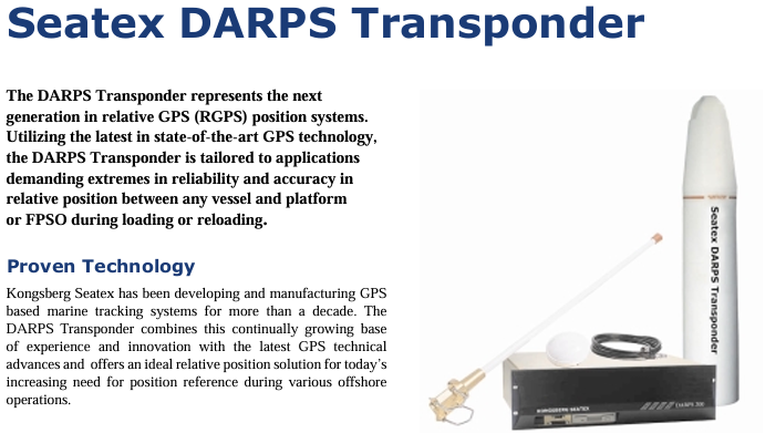
Kongsberg Maritime’s Seatex DARPS Transponder is a new generation relative GPS (RGPS) positioning system responder developed based on advanced GPS technology. Its core function is to provide high reliability and precision relative position reference for offshore operation scenarios, such as ship and platform/FPSO loading and unloading operations. Through integrated design and intelligent communication protocols, it adapts to the multi device collaborative positioning requirements in extreme offshore environments.
Core positioning and technological advantages of the product
1. Core application scenarios
Specially designed for offshore operations that require precise relative positioning, with a focus on addressing:
Position monitoring during loading, unloading, and supply operations between ships and fixed platforms (such as FPSOs and offshore drilling platforms);
The relative positioning of multiple ships working together in the same area to avoid operational risks caused by collisions or positional deviations.
2. Key technological advantages
Mature technology accumulation: Kongsberg Seatex has over ten years of experience in the development of GPS maritime tracking systems. The responder integrates continuous iteration of technical experience with the latest GPS developments to ensure positioning stability.
Highly integrated: All electronic components, GPS antennas, and UHF antennas are integrated into a single physical unit, requiring only one power cord to connect and automatically start when powered on, greatly simplifying installation and maintenance.
Anti harsh environment capability: Made of polyethylene shell, electronic components are designed for harsh marine environments, with a protection level of IP68 (able to withstand short-term immersion in 10 meters of water depth), suitable for offshore conditions such as salt spray, humidity, and vibration.
Multi device collaboration capability: Based on the Time Division Multiple Access (TDMA) protocol, it supports up to 24 ships sharing the same UHF frequency, with an update rate as fast as 2 seconds per time, meeting the requirements of multi ship synchronous operations.
Core functions and working principles
1. Relative positioning workflow
Data collection: The responder has a built-in GPS receiver that captures L1 C/A code and carrier phase signals, while also having anti multipath interference function to reduce signal attenuation and ensure the accuracy of the original data.
Data transmission: GPS raw data and responder status parameters are transmitted to the DARPS 100 host system on board via a UHF wireless link (bidirectional communication); If the ship sends RTCM correction data, the responder can output DGPS positioning results, further improving accuracy.
Position calculation: After receiving data, the DARPS 100 system on board accurately calculates the relative position between the ship and the responder (and corresponding platform); A single responder can communicate with multiple ships equipped with DARPS 100 simultaneously, achieving collaborative positioning among multiple ships.
2. Core functional highlights
High precision positioning: Based on L1 C/A code measurement technology, combined with anti multipath interference design, it ensures relative positioning accuracy and meets the strict requirements for position error in offshore operations.
Intelligent data verification: By using reliable data protocols to detect and eliminate erroneous data, invalid results can be avoided from affecting RGPS operations, ensuring reliable positioning.
Remote configuration and monitoring: Key parameters of the responder (such as UHF frequency, GPS update rate, TDMA time slot) can be remotely modified through the DARPS 100 control unit or handheld controller on board, and all status parameters (such as power supply, signal strength, working mode) can be monitored in real time to prevent sudden failures.
Flexible frequency selection: Provides two UHF frequency bands (450-470MHz standard band, 868-870MHz optional band), with easily adjustable frequencies within the band to adapt to radio spectrum planning in different sea areas.
Detailed explanation of technical specifications
1. General and GPS parameters
Category specific specifications
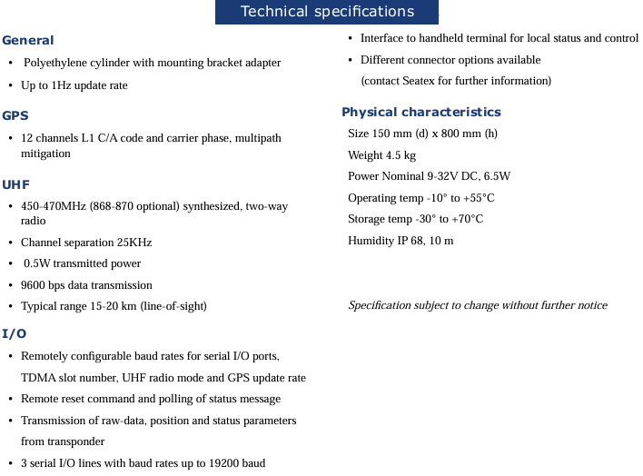
General characteristic appearance: polyethylene cylindrical (with mounting bracket adapter); Update rate: up to 1Hz; Protection level: IP68 (10 meter water depth)
Number of GPS performance channels: 12 channels (supporting L1 C/A code and carrier phase measurement); Core function: multi-path interference suppression
2. UHF radio parameters
Parameter specifications
Frequency range standard: 450-470MHz; Optional: 868-870MHz (Synthetic Bidirectional Radio)
Channel spacing of 25KHz
Transmitting power 0.5W
Data transmission rate 9600 bps
Communication distance (line of sight) typically 15-20 kilometers
3. Interface (I/O) and Control
Serial interface: 3 serial I/O lines, maximum baud rate 19200 bps; Support remote configuration of baud rate, TDMA time slot number, UHF radio mode, and GPS update rate.
Control mode: Supports remote reset commands and status message polling; Can connect to handheld terminals for local status viewing and control; Multiple connector options are available (please contact Seatex for detailed information).
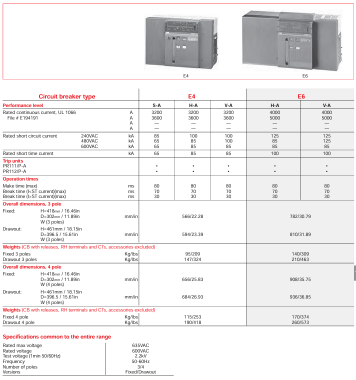
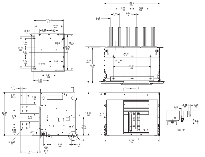
The ABB E max series low-voltage power circuit breaker (Sace) is an innovative product developed based on over half a century of circuit breaker technology. It has high reliability, easy installation, and flexible adaptability. It has passed UL certification and complies with ANSI low-voltage power circuit breaker standards, covering a rated continuous current range of 800A-5000A and a rated short-circuit current range of 42kA-125kA (480V). It is suitable for distribution systems, industrial equipment, and other scenarios, providing efficient power protection solutions for designers, switchgear manufacturers, installers, and users.
Core product classification and key parameters
1. Model and frame specifications
The series includes five models (four sizes): E1, E2, E3, E4, and E6. The differences in core electrical parameters are as follows (taking UL standards as an example):
Model Rated continuous current (A) 480V Rated short-circuit current (kA) Number of poles Installation method Typical weight (kg/lbs, 3 poles fixed)
2. General technical specifications (shared by UL and IEC)
Voltage and Frequency: Rated maximum voltage 635VAC, rated operating voltage 600VAC, test voltage (50/60Hz for 1 minute) 2.2kV, applicable frequency 50-60Hz.
Temperature range: Operating temperature -5~+70 ° C, storage temperature -40~+70 ° C, suitable for different temperature zones in industrial sites.
Neutral pole rating: The neutral pole rating for E1-E3 models is 100% of the rated current, and for E4-E6 models it is 50% (special requirements can be consulted with the manufacturer to customize the 100% rating).
Mechanical and electrical lifespan: Mechanical lifespan (under routine maintenance) 20000-25000 operations, electrical lifespan (440VAC) 10000-30000 operations, with a maximum operating frequency of 60 times per hour.
Core functions and structural characteristics
1. Protection and control capability
Release Unit: Standard PR111/P series release, supporting LI (Long Delay Instantaneous), LSI (Long Delay Short Delay Instantaneous), and LSIG (Long Delay Short Delay Instantaneous Ground Fault) protection functions; PR112/P and PR113/P series are optional, suitable for more complex scenarios (such as PR112/PD supporting communication functions).
Operation time: The maximum closing time is 80ms, the maximum opening time (I<short-circuit withstand current) is 70ms, and the maximum (I>short-circuit withstand current) is 30ms. It can quickly respond to faults and reduce equipment damage.
Auxiliary functions: Comes with 2NO+2NC auxiliary contacts (for indication of opening and closing status), spring energy storage/release mechanical indicators, and manual opening and closing buttons; The pull-out model is equipped with a rocking in device with a closed door, a rocking in position indicator, and an anti insertion lock to enhance operational safety.
2. Installation and structural design
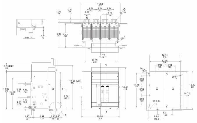
Size and Installation: Fixed 3-pole model with a height of approximately 418mm (16.46 inches) and a depth of 302mm (11.89 inches); The pull-out depth has been increased to 396.5mm (15.61 inches), supporting DIN rail or 19 inch rack installation (requires installation kit).
Terminal and wiring: default rear horizontal terminal, optional rear vertical, front terminal and other types (such as “HH” representing rear horizontal and “HV” representing rear horizontal vertical in the model), suitable for different switchgear wiring requirements; The terminal box is integrated with the current transformer (CT) to simplify on-site wiring.
Redundancy and reliability: The pull-out model is designed with a “mobile part+fixed part” separation, supporting hot swappable replacement; Key components such as sliding contacts and trip units have anti vibration capabilities (7.35 m/S ², 5-500Hz) and comply with ISA S71.04 G3 harsh environment standards.
Product configuration and optional accessories
1. Basic configuration classification
According to the operation mode and function, there are mainly two types of products:
Automatic air circuit breaker: including trip unit and current transformer, supporting fault protection such as overcurrent and short circuit, divided into fixed and withdrawable types, suitable for distribution circuits that require automatic protection.
Non automatic air circuit breaker (switch): no trip unit and CT, only used as a manual or electric power switch, also available in fixed/withdrawable type, suitable for simple circuits that do not require complex protection.
2. Optional attachments (UL and IEC compatible)
Attachment category, specific function and model, example usage
Electrical accessories include shunt release coil (KE6S0, 24VDC), closing coil (KE6C6110-120VAC), and spring energy storage motor (KE6M5110-130VAC/VDC) for remote opening and closing and automatic spring energy storage
Mechanical accessory button protective cover (KE6PG), padlock device (KE6PD1), mechanical counter (KE6MC) to prevent misoperation, lock circuit breaker position, record operation times
Additional auxiliary contacts (KE6A15, 15 sets), position indicator contacts (KE6PS1, 5 sets), extended status monitoring signal, indication of withdrawable circuit breaker position
Interlocking and protective mechanical interlocking (KE6MLP, fixed circuit breaker base), transparent front cover (KE6DC, IP54 protection) achieve multi circuit breaker interlocking control and improve dust and water resistance
Test and Diagnostic Handheld Test Kit (K7TUT, suitable for PR111), Configuration Unit (PR010/T) for on-site testing of trip function and configuration of trip parameters
Model coding rules (taking UL as an example)
Taking “E1S16XXXXXXXXXX” as an example, the key codes have the following meanings to facilitate selection according to requirements:
Power distribution: used for the main circuit of low-voltage distribution systems, protecting key equipment such as transformers and busbars, and adapting to E4-E6 high current models.
Industrial equipment: provides short-circuit and overload protection for industrial loads such as motors and frequency converters, and E1-E3 small-sized models are suitable for compact layout of switchgear.
Commercial buildings: As the main switch for power distribution, the pull-out design is convenient for later maintenance and replacement.
Compliance and Certification
Safety certification: UL/UL-C certification (applicable to Class I, Groups A-D, Division 2 explosion-proof areas), ATEX certification (Ex nA IIC T4, Zone 2 areas), IEC 60947-2 standard compliance.
Environmental requirements: Compliant with RoHS directive, halogen-free design, reduces harmful substance emissions, suitable for green industrial scenarios.
This product is the industrial grade PROFIBUS-DP network interface card series launched by Woodhead (now under Schneider Electric). Its core positioning is to build a direct communication bridge between PC based control applications and I/O devices, supporting multiple hardware forms and operating systems, with high data throughput, flexible configuration, and ease of use. It is suitable for real-time data acquisition and control in industrial automation scenarios.
Core positioning and overall characteristics of the product
1. Core values
Communication intermediary: realizes direct connection between PC based control applications and PROFIBUS-DP I/O devices, supports deterministic I/O data acquisition, and meets real-time control requirements.
Low cost and high compatibility: It belongs to the entry-level industrial communication component, with high cost-effectiveness, modularity, and scalability. It can be easily embedded in computerized systems and adapted to industrial applications of different architectures.
2. Key common characteristics
Protocol support: Covering multiple PROFIBUS-DP protocol modes to meet the needs of different communication roles:
Basic support: PROFIBUS-DP V0 master station (Class 1/2), V0 slave station (active/passive mode);
Advanced support: Only PCI Universal models support PROFIBUS-DP V1 master station (Class 1/2).
Configuration and diagnosis: Equipped with one serial or Ethernet port (depending on the model) for remote configuration and diagnosis; Support automatic detection of network devices, store configuration parameters in Flash memory, and support automatic startup mode.
Performance optimization: onboard embedded communication module improves data throughput; Equipped with intelligent A.D.M (automatic dual port RAM mapping) mechanism, there is no need to configure I/O tags in the dual port RAM of the card, reducing the load on the host CPU; Provide additional functions such as device status, diagnostic information, process data read-write monitoring, software and hardware watchdog, etc.
Compliance: Compliant with RoHS standards (some models have new features), and a member of the PROFIBUS industry organization (PTO, PNO, France Profibus), with guaranteed protocol compatibility.
Hardware model and technical specifications
This series offers three hardware forms that are compatible with different PC bus types. The differences in core parameters are shown in the table below:
Model category: Direct Link ™ PCU-DPIO(PCI-Universal) Direct-Link ™ PC104-DPIO (PC/104 bus) Direct Link ™ CPCI-DPIO (CompactPCI Bus)
Bus and voltage PCI Universal 3.3V/5V, compatible with PCI-X PC/104 bus CompactPCI bus, 5V power supply
Discrete I/O 1-channel optocoupler discrete input (24V AC/DC, 0.25A); 1 watchdog output (floating contact) same as PCU-DPIO same as PCU-DPIO
Dimensions (length x width) 168mm x 107mm (6.61 inches x 4.21 inches) 95mm x 90mm (3.74 inches x 3.54 inches) 100mm x 160mm (3.93 inches x 6.29 inches)
Maximum power consumption 5.5W (1.2A) Maximum 5.5W (1.2A) Maximum 5.5W (1.2A)
Working temperature: 0 ° C (32 ° F)~+65 ° C (149 ° F) 0 ° C (32 ° F)~+65 ° C (149 ° F) 0 ° C (32 ° F)~+65 ° C (149 ° F)
Storage temperature -40 ° C (-40 ° F)~+85 ° C (185 ° F) -40 ° C (-40 ° F)~+85 ° C (185 ° F) -40 ° C (-40 ° F)~+85 ° C (185 ° F)
Configure Ethernet port (10/100 Mbps, RJ45 interface) Asynchronous serial port (RS232, 2 signals) Asynchronous serial port (RS232, 2 signals)
LED indicator light PROFIBUS: 2 dual color lights (bus fault/communication status); Ethernet: 4 lights (TX/RX/Link/100Mbps) PROFIBUS: 2 dual color lights; Serial port without additional indicator lights PROFIBUS: 2 dual color lights; Serial port: 2 lights (TX/RX)
RoHS Compliance Yes (New Feature) No Yes (New Feature)
Additional notes
PROFIBUS speed: All models support adjustable speeds ranging from 9.6 kbps to 12 Mbps, in compliance with the EN 50170 standard.
Plug and Play (PnP): PCU-DIPIO and CPCI-DPIO support hardware PnP, while PC104-DPIO requires manual address configuration (address range C8000~DE000, single card occupies 8 Kbytes).
Protocol Function Details
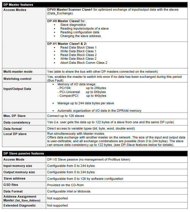
1. PROFIBUS-DP main station features (all models support V0, PCU-DIPO additionally supports V1)
Main station type core function
DP-V0 Class 1 optimizes the I/O data exchange with the slave station to ensure real-time performance.
DP-V0 Class 2 implements slave diagnosis, reads slave I/O data, writes data blocks (Class 1/2), and terminates data block communication (Class 2).
DP-V1 Class 1/2 is only supported by PCU-DPIO, expanding the functionality of the main station and adapting to more complex communication requirements.
Common capability can connect up to 126 slave stations; Support direct access to variable types such as bit, byte, word, and doubleword; It can share the bus with other main stations in the network, and supports up to 122 bytes of input/output data consistency.
Access mode: DP-V0 slave passive mode, does not manage PROFIBUS tokens.
Memory configuration: Input/output memory size can be configured (0-244 bytes).
Address and format: The slave address can be configured through software (0~126); The data format supports Intel or Motorola formats.
Limitations: The “Set_Slave_Address” and “Extended Diagnostic” functions are not supported; Provide GSD files (included with CD-ROM) for system integration configuration.
Software Support and Tools
1. Compatible with operating systems
Covering mainstream and industrial specific operating systems to meet the needs of different control scenarios:
Standard Windows: 32-bit Windows XP SP1/2000 SP4/NT SP6/2003 Server;
Embedded systems: Windows XP Embedded, QNX, VxWorks, Linux, Phar Lap ETS, DOS;
Real time extension: Ardence RTX (hard real-time extension).
2. Software suite (included in standard packaging)
Configuration and Diagnostic Console: A core tool that supports graphical interface operations, with features including:
Parameter configuration of cards, networks, and fieldbus devices;
Dynamic network diagnosis, definition of I/O data access items (adapted to OPC servers, ActiveX controls, and other interfaces);
Automatically detect cards inserted into the host, manage user configuration (create/backup/restore), and manually/automatically configure devices;
PROFIBUS scanning (automatic detection of connected slave stations and configuration), GSD library management (adding/deleting GSD files);
Card status indication (quick view of initialization status), troubleshooting and testing.
Data Server and Driver:
Multi protocol OPC server (supporting DA 3.0/2.05), ActiveX controls, DAServer, FastDDE/SuiteLink server;
I/O libraries (DLLs), Ardence RTX real-time extension libraries, and non Windows OS static libraries in the Windows environment;
Software logic package driver, compatible with third-party control software.
This product is a thin client designed specifically for Foxboro distributed control system (DCS) by Schneider Electric, based on HP ® The T755 hardware platform is equipped with the Windows 10 IoT Enterprise LTSC 2021 system, which enables DCS system monitoring and operation through remote connection in a compact form. It is suitable for traditional and virtualized Foxboro DCS environments, with both ease of use and high security, and supports flexible networking and redundant configuration.
Core positioning and basic configuration
1. Product essence and hardware selection
Definition: A thin client is a physical hardware terminal that accesses the server-side operating system through remote connections, enabling DCS system event monitoring and response. Compared to workstations, it is smaller in size and can be locally deployed on the user side.
Hardware specifications: designated to use HP ® The T755 model only offers the dual network card (RH103HM) version, and the single network card version has been discontinued; Standard QWERTY keyboard, software installation requires a USB DVD drive (used for installing thin client software, SE RDP connection manager, and alarm keyboard software).
2. Optional configuration (to be purchased separately)
Display device: Supports up to 4 LCD monitors, corresponding to models P0928JJ (23 inch USB touch screen monitor) and RH103FR (24 inch LCD monitor).
Audio and input devices: USB speaker (model RH103DN), up to 4 alarm keyboards (models P0924TT, P0924WV); If the thin client is equipped with a QWERTY keyboard, FoxPanels can be used instead of the alarm keyboard.
Functions and core features
1. Remote access and DCS interaction
Access object: Foxboro DCS software suite can be obtained by connecting to the following remote servers through the network:
H90 and H94 physical servers running Windows Server system;
Virtual machines (VMs) deployed on Foxboro DCS V91 and V95 virtualization hosts.
Communication method: Connect physical or virtual auxiliary communication network (ACN, composed of managed Ethernet switches) through 1GB copper cable Ethernet, Schneider Electric provides dedicated engineering processes for establishing network connections; Supports single or redundant network card connections. If a RDP server failure is detected, it can automatically switch to another server.
Operational capability: As a Human Machine Interface (HMI) station, through Microsoft ® Remote Desktop Services or SE RDP Connection Manager can remotely view and manage DCS software suites, performing operational tasks similar to workstations.
2. Configuration flexibility
Support multiple deployment configurations to meet different usage scenarios:
Restricted connection: Only allow connections to specific virtual machines or physical DCS servers.
Automatic connection: Automatically connects to a single virtual machine or physical server after booting up.
Redundancy and Multiple Connections: Multiple virtual machines/physical servers can be connected (supporting “one redundancy at a time”), or multiple devices can be automatically connected upon startup; It can also be used in non domain environments of local version Control Core Services and enterprise version Control Core Services.
3. Performance and Capacity Limitations
Session support: A single server running Microsoft Remote Desktop Services can support up to 30 FoxView remote sessions and 10 Control HMI remote sessions; Due to the bandwidth limitation of physical Ethernet ports, the total number of RDP sessions for all virtual machines on the virtualization host server does not exceed 60 (the actual number is affected by the type and number of applications running in the sessions).
4. Network security
Access control: thin clients can be configured to only connect to specific remote servers; The remote server assigns corresponding operation permissions based on the logged in user’s configuration file.
Additional protection: optional Trellix Terminal Security (ENS) enhanced protection, providing advanced threat defense capabilities; When purchasing the T755 thin client, the Trellix ENS license rights for the first 5 years are included, and renewal is required after 5 years.
Reference document: For detailed security specifications and best practices, please refer to EcoStruxure ™ Foxboro ™ DCS Network Security Reference Guide “(document number B0700HZ).
License authorization requirements
Two types of licenses must be met to ensure legal use:
1. Foxboro DCS related licenses
There is no specific hardware or software license for thin clients, and the existing Foxboro DCS software suite license still applies, but the license belongs to the remote server (non thin client).
Both physical servers and virtual machines, as well as the thin clients connected to them, require corresponding Foxboro DCS software suite licenses. The specific license model needs to be determined based on the type of DCS software installed on the server/thin client.
2. Microsoft License
Free session management: Windows Server allows 2 remote access sessions without CAL (Client Access License), used only for management and technical support, and does not occupy local desktop session resources.
Additional RDS CAL License: If you need more remote connections, you need to purchase a Remote Desktop Services (RDS) client access license (formerly Terminal Services CAL), which supports both “per user” and “per device” authorization modes and can be purchased on the BuyAutomation platform. The specific models and specifications are shown in the table below:
Product Number (P/N) CAL Type Quantity
J0202AW RDS 2016 Device License 5
J0202AV RDS 2016 User License 5
J0202EC RDS 2022 Device License 5
J0202EB RDS 2022 User License 5
J0202EF RDS 2022 Device License 1
J0202EG RDS 2022 User License 1
License rules: The “per device” license must be assigned to one device (thin client, computer, portable device) accessing the remote desktop session, and the license cannot be reused after binding the device; The ‘per user’ license needs to be assigned to one user for each access session, regardless of the device used by the user; All RDS CALs must be installed and activated on a licensed server (usually an RDS server), and Foxboro DCS servers do not come with any RDS CALs at the factory.
Hardware and Technical Specifications
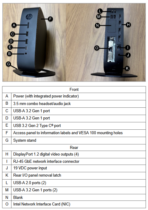
1. Hardware structure and interface (HP t755)
Location interface/component function description
Front A: Power (with indicator light) Power switch and status indicator
B: 3.5mm combination headphones/audio interface for connecting headphones or audio devices
C/D: USB-A 3.2 Gen 1 port for connecting external USB devices (such as mice, printers, etc.)
E: USB 3.2 Gen 2 Type C port high-speed USB connection, supports external devices
F: Information label and VESA 100 installation hole panel for viewing device information, supporting VESA 100 standard installation
G: The system bracket supports vertical or horizontal placement
Back H: Display Port 1.2 interface (4) for connecting LCD displays, up to 4 units
K: Disassemble the latch of the rear I/O panel and remove the operating components of the rear I/O panel
L: USB-A 2.0 ports (2) for connecting low-speed USB devices
M: USB-A 3.2 Gen 1 ports (2) for connecting high-speed USB devices
N: Blank interface reserved or unused interface
O: Intel network card for network communication, dual network card configuration for redundancy
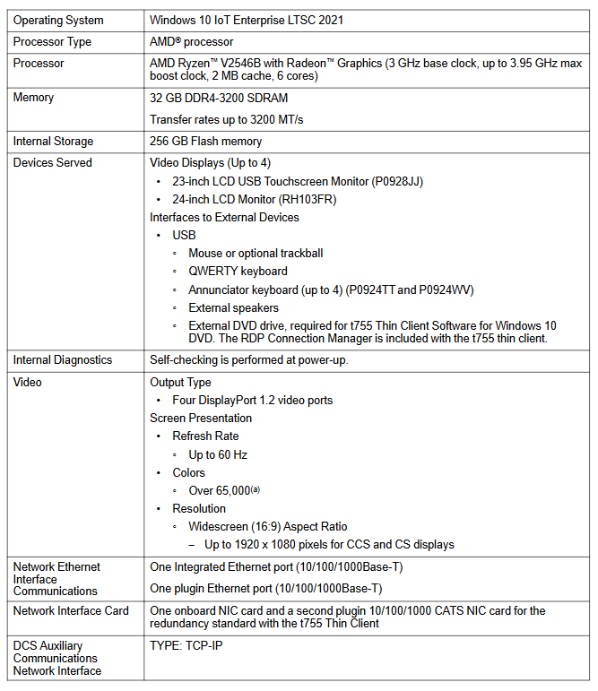
Core hardware parameters: AMD ® Ryzen ™ V2546B processor (3GHz reference frequency, up to 3.95GHz acceleration frequency, 2MB cache, 6 cores), 32GB DDR4-3200 SDRAM (maximum transfer rate of 3200MT/s), 256GB flash memory; Integrate one Gigabit Ethernet port and add one plug-in Gigabit Ethernet port, with dual network cards supporting network redundancy.
2. Functional specifications
Category detailed parameters
Operating System Windows 10 IoT Enterprise LTSC 2021
External devices support mouse/trackball (optional), QWERTY keyboard, alarm keyboard, external speakers, touch screen, USB printer (optional)
Built in diagnostics automatically perform self check upon startup
Display performance: 4 DisplayPort 1.2 video ports, maximum refresh rate of 60Hz, over 65000 colors (limited by software), widescreen (16:9) resolution up to 1920 × 1080 pixels (suitable for CCS and CS displays)
One integrated Gigabit Ethernet port and one plug-in Gigabit Ethernet port for network interface; The DCS ACN interface protocol is TCP/IP
The power supply requires an input voltage of 100-240VAC (automatic switching), a frequency of 50-60Hz, and a maximum power consumption of 90W (actual power consumption is affected by software load, peripherals, and environment)
3. Environmental and physical specifications
Environmental adaptability:
Scene temperature range, humidity range, altitude range
Run at 10-40 ° C (50-104 ° F) with 10% -90% (no condensation) and 20% -80% (condensation) for 300m-3km (1000-10000ft)
Installation method: desktop placement, VESA 100 standard installation;
Weight: 1297g (2.86 pounds);
Heat dissipation: Under a 90W power supply, the heat dissipation varies under different operating conditions (such as 28.14 BTU/hour in short idle state and 2.73 BTU/hour in sleep state at 100VAC 60Hz).
Compliance: Complies with Section 508 accessibility standards (VPAT report available); For product safety, EMC, and environmental compliance information, please refer to the t755 thin client product information on the HP official website.
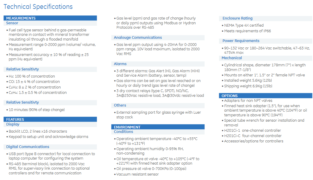
Sensor technology: using fuel cell type sensors with breathable membranes, in contact with mineral transformer insulation oil through “dynamic oil sampling” technology, without the need for pumps or additional pipelines; Optional 5-year sensor warranty.
Monitoring range and accuracy: The H ₂ equivalent measurement range is 0-2000ppm (volume ratio), with an accuracy of ± 10% ± 25ppm of the reading; Fast response speed, 90% step change only takes 10 minutes.
Gas sensitivity: 100% response to H ₂ (universal fault gas), while sensitive to CO (paper overheating), C ₂ H ₂ (arc discharge), and C ₂ H ₄ (oil overheating), covering all major fault sources of transformers.
2. Display and operation
Equipped with a backlit LCD display screen (2 lines x 16 characters), it can display the dissolved gas ppm value in real time.
Comes with a built-in keyboard that supports device settings and alarm confirmation operations.
3. Communication function
Local communication: Equipped with a USB B-type interface, it replaces the RS-232 interface that has been removed from most on-site laptops, making it convenient to connect to a computer and configure the system locally.
Remote communication:
Analog output: 4-20mA signal (corresponding to 0-2000ppm range), maximum load 10V, insulation level 2000Vac RMS.
Digital output: Through an isolated RS-485 interface, supporting Modbus or Hydran protocols, outputting gas ppm values and hourly/daily gas change rate (ROC).
Dry contact relay: 3 SPDT type relays (C type), 2 for fault gas alarm, 1 for service alarm, rated load: 3A@250Vac or 3A@30Vdc .
4. Alarm and self check
Configurable alarms: Supports two-level gas alarms (Alert warning, Alarm emergency), which can be set based on gas ppm concentration or hourly/daily change rate; Triggering an alarm when abnormal fault gas levels are detected.
Automatic self check: Conduct a self check every 15 days. If power failure, oil valve closure, sensor or battery replacement issues are found, a service alarm will be triggered.
Installation and compatibility
1. Installation characteristics
Single valve installation design, directly installed on the transformer oil valve without the need for additional pipelines or pumps; Compatible with 1-inch, 1.5-inch, and 2-inch internal thread NPT valves.
The shape is cylindrical, with a diameter of 178mm (7 inches) and a length of 180mm (7 and 1/8 inches); Installation weight 5.6Kg (12 pounds), transportation weight 6.9Kg (15 pounds).
Optional accessories: Non NPT valve adapter, fin heat dissipation adapter (used when the ambient temperature exceeds 40 ° C or the oil temperature exceeds 90 ° C), sensor installation/removal special pipe wrench.
2. Controller and Networking
Can connect optional controllers to build a local network, supports RS-485 “daisy chain” connection, can connect up to 32 controllers or 201Ti devices in series, with a total chain length of up to 1200m (4000 feet), and all devices can be accessed through any controller in the network.
Two types of core controllers:
Ci-1 single channel controller: replicates some human-machine interaction functions (gas value display, alarm button), suitable for use when installing 201Ti in high position valves of transformers. It also leads out alarm relay contacts and analog outputs for easy wiring.
Ci-C four channel controller: capable of receiving gas ppm data from 4 201Ti units, providing a single communication point, no alarm relay, and analog output, suitable for protecting 3 single-phase transformers and 1 backup transformer scenarios.
3. Software compatibility
Compatible with GE’s well-known Perception Fleet software, supporting data download, trend analysis, and management, and operating logic consistent with other GE DGA monitoring devices.
Environmental and power requirements
1. Environmental adaptability
Working environment temperature: -40 ° C to+55 ° C (-40 ° F to+131 ° F).
Working environment humidity: 0-95% RH (non condensing).
Oil temperature at the valve: -40 ° C to+105 ° C (-4 ° F to+221 ° F, requires fin heat dissipation adapter).
Oil pressure at the valve: 0-700KPa (0-100psi), the sensor has anti vacuum capability.
Protection level: NEMA 4X certified, meets IP66 requirements.
2. Power parameters
AC power supply: switchable between 90-132Vac or 180-264Vac, frequency 47-63Hz, maximum power consumption 475VA.
Applicable scenarios
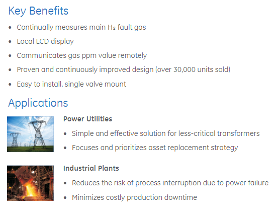
1. Power Utilities
Provide a simple and effective monitoring solution for non critical transformers.
Focus and prioritize the replacement strategy of auxiliary assets to optimize asset management.
2. Industrial Plants
Reduce the risk of production process interruption caused by power failures.
Reduce high production downtime losses and ensure continuous production.
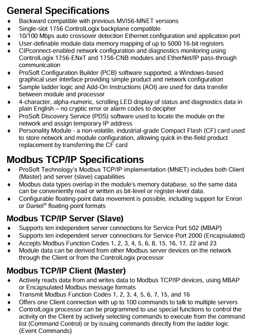
MVI56E-MNET/MNETXT is a single slot ControlLogix backplane compatible module that serves as a communication bridge between Rockwell Automation ControlLogix processors and Modbus TCP/IP devices. It supports both Modbus TCP/IP client (Master) and server (Slave) functions, enabling data exchange with Modicon programmable automation controllers (PAC) and various Modbus TCP/IP compatible instruments and devices.
The two models have completely identical functions, only applicable in different environments:
MVI56E-MNET: Targeting standard industrial control scenarios and meeting conventional environmental requirements;
MVI56E-MNETXT: specifically designed for Logix XT ™ Control platform design with conformal coating, capable of withstanding extreme temperatures and corrosive environments, suitable for harsh industrial scenarios such as chemical and outdoor equipment.
Core Features and Advantages
The module reduces the deployment and maintenance costs of industrial communication through its three core features of compatibility, integration, and ease of use, as follows:
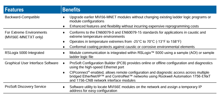
Specific description of characteristic categories and core advantages
Backward compatibility is fully compatible with early MVI56-MNET modules, and can be upgraded without modifying existing ladder logic programs or module configurations, avoiding secondary development costs during upgrades and protecting historical investments
The integrated communication function of RSLogix 5000 can be achieved through RSLogix ™ The example additional instructions (AOI) or ladder logic files in 5000 enable seamless integration with the ControlLogix control system, reducing cross platform configuration complexity
Graphic configuration and diagnostic support for ProSoft Configuration Builder (PCB) software, enabling online/offline configuration through high-speed Ethernet ports; Built in CIPconnect ® Technology can be used across EtherNet/IP through the 1756-ENxT/1756-CNB module ™/ ControlNet ™ Network remote management simplifies the configuration process, supports remote operation and maintenance, and reduces on-site debugging workload
ProSoft Discovery Service (PDS) tool is used for network discovery and IP management, which can quickly locate modules in the network and allocate temporary IPs to solve the problem of complex module IP configuration in industrial scenarios, improving deployment efficiency
Non volatile storage equipped with industrial grade Compact Flash (CF) “personality module”, storage network and module configuration; When a module fails, simply transfer the CF card to complete the replacement, achieving a “plug and play” replacement and reducing system downtime
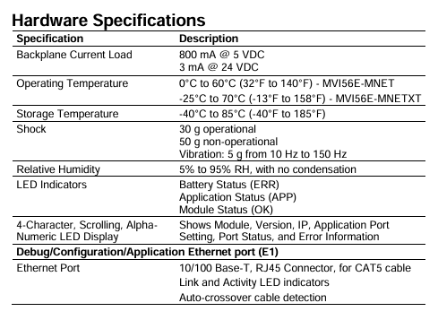
Intuitive display of 4-character Alpha Numeric scrolling LED screen, displaying module status in plain English IP、 Port information and errors (no obscure code); Paired with ERR/APP/OK three color LED indicator lights, faults can be quickly located, reducing the difficulty of operation and maintenance troubleshooting
Modbus TCP/IP communication capability
The module supports both Client (active initiating communication) and Server (passive receiving communication) modes, covering the bidirectional data exchange requirements between the control end and the device end in industrial scenarios. The specific specifications are as follows:
1. Modbus TCP/IP Server (Slave, server mode)
Connectivity: Supports independent connections between two types of ports, with a maximum of 10 connections per type of port
Service Port 502 (Standard MBAP Protocol);
Service Port 2000 (encapsulation protocol).
Support function codes: Function Code 1 (read coil), 2 (read discrete input), 3 (read hold register), 4 (read input register), 5 (forced single coil), 6 (pre-set single register), 8 (diagnostic), 15 (forced multi coil), 16 (pre-set multi register), 17 (report slave ID), 22 (mask write register), 23 (read/write register).
Data source: Module data can come from ControlLogix processors or other Modbus Server devices in the network (obtained through Client mode).
2. Modbus TCP/IP Client (Master, client mode)
Communication capability: 1 client connection, supports up to 100 instructions, can communicate with multiple server devices; Supports MBAP or encapsulated Modbus message format.
Support function codes: Function Code 1, 2, 3, 4, 5, 6, 7 (read abnormal status), 15, 16.
Control method: The ControlLogix processor can control client behavior in two ways:
Command Control: Actively select the instructions to be executed from the instruction list;
Event Commands: Directly issue commands through ladder logic.
3. Data processing characteristics
Memory Mapping: Supports user-defined data memory mapping for up to 5000 16 bit registers, meeting the needs of large capacity data exchange.
Data flexibility: Modbus data types can overlap in the module’s memory database, and the same data can be read and written at the “bit level” or “register level”; Support floating-point data transfer (including Enron and Daniel) ® Floating point format).
Software and hardware specifications
1. Hardware specifications
Specification category specific parameters
Backplane compatibility single slot 1756 ControlLogix backplane, supporting local rack and remote rack deployment
Backboard current load 5VDC: 800mA; 24VDC:3mA
Ethernet port (E1) 10/100 Base-T, RJ45 interface (compatible with CAT5 cable); Support automatic cross cable detection; Equipped with Link/Activity LED indicator light
Impact resistance performance during operation: 30g; non operation: 50g
2. Functional specifications
Data transmission optimization: Transfer data at the maximum I/O image block size to improve throughput and update speed.
Module identification: Recognized as an “I/O module” (non communication module) in the ControlLogix processor, adapted to the system’s native I/O management logic.
Special function support: Through the “block transfer code” in ladder logic, special operations such as module state reading, instruction control, and event instructions can be achieved.
Derivative models: Provide MVI56E-MNETR model (remote rack optimized version), support reducing data block size, and adapt to remote rack bandwidth limited scenarios.
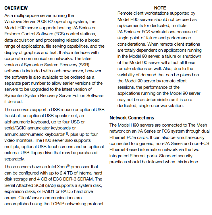
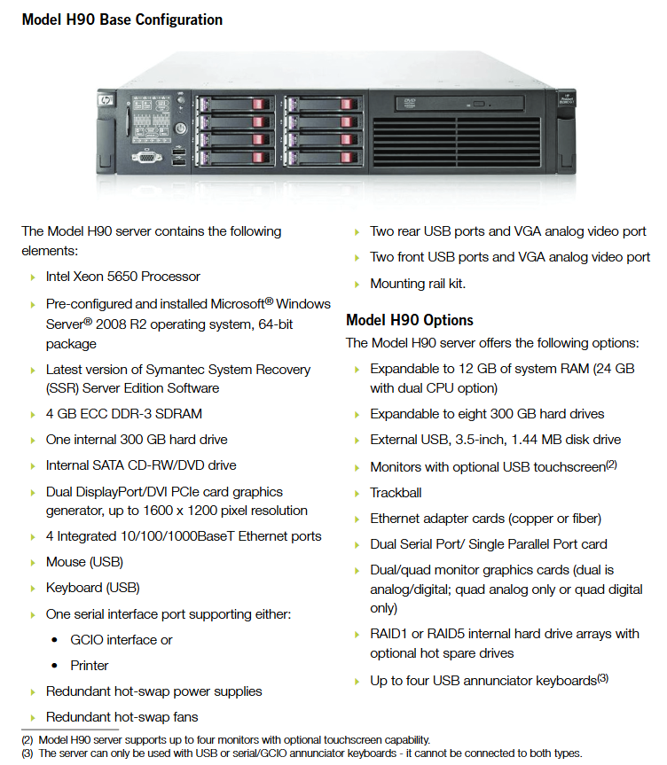
Model H90 is a 2U rack mounted server level workstation pre installed with Microsoft Windows Server ® 2008 R2 (64 bit) operating system, with Foxboro as its core positioning ™ I/A Series or Foxboro Control System (FCS) is a “multi-purpose application platform” that simultaneously undertakes tasks such as control station hosting, data collection and monitoring, human-machine interaction (HMI), file services, etc. It supports the distribution of application views to remote clients through a local area network (LAN) and is suitable for central control requirements in industrial scenarios that require high server performance, redundancy, and security.
1. Core functions
Multi role support: It can serve as a control station (running I/A Series/FCS control software), data acquisition station (processing various on-site device data), human-machine interface station (displaying graphic and text information), and also supports file services and enterprise network integration.
Hardware redundancy guarantee: standard redundant hot swappable power supply, redundant hot swappable fan, optional RAID1/RAID5 disk array (including hot spare), to avoid system interruption caused by single point of failure.
Peripheral expansion capability: Supports up to 4 displays (including USB touch screen), 4 USB alarm keyboards (or 2 serial/GCIO alarm keyboards), external USB floppy disk drives, printers, etc., to meet complex human-computer interaction needs.
Security Protection Kit: Pre installed McAfee ® A complete set of security software, including virus protection, host intrusion prevention, data leakage protection, etc., in compliance with industrial security standards (such as NERC CIP).
2. Basic adaptation requirements
Software dependency: Requires I/A Series S10 software license, supporting I/A Series software v8.2-v8.8 or Control Core Services (CCS) v9.0 and above versions; Pre installed with the latest version of Symantec System Recovery (SSR) Server Edition software, supporting system backup and recovery.
Network connection: Connect to the Mesh network of I/A Series/FCS through dual PCIe Ethernet cards, and also connect to non control information networks through two integrated Ethernet ports (subject to standard security specifications).
Key features and technological advantages
1. Core Features
Specific description of characteristic categories
The high-performance hardware configuration is equipped with Intel Xeon 5650 processor, standard with 4GB ECC DDR-3 SDRAM (expandable to 12GB, up to 24GB in dual CPU configuration), internal storage supports up to 8 300GB hard drives (total capacity 2.4TB), supports SAS interface and RAID array, meeting the high requirements of industrial control for computing power and storage.
Full redundancy design – power supply: 2 750W hot swappable redundant power supplies (100-240VAC wide input);
-Heat dissipation: Redundant hot swappable fans to avoid overheating and shutdown;
-Storage: RAID1 (mirror)/RAID5 (distributed parity) disk array, optional hot spare to prevent data loss;
-Network: Dual network cards are redundantly connected to the Mesh network to ensure communication continuity.
Industrial grade security protection based on McAfee ® Building multi-layered protection with software suite:
-VirusScan with AntiSpyware Enterprise: Real time scanning and killing of viruses and spyware, automatic updating of virus databases;
-EPolicy Orchestrator (ePO): Centralized management of all McAfee products, unified distribution of policies and updates;
-Host Intrusion Prevention (HIP): Proactively intercepting zero day attacks and unauthorized access, supporting port control and application blacklisting;
-Data Loss Prevention (Device Control): Control the hardware ports (floppy drives, optical drives, USB, etc.) of Windows 7 workstations to prevent data leakage.
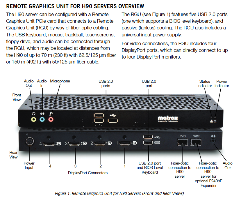
Flexible remote expansion support enables remote deployment of peripherals through Remote Graphics Unit (RGU):
-Adopting fiber optic transmission, supporting 62.5/125 μ m multimode fiber (up to 70m) or 50/125 μ m multimode fiber (up to 150m);
-It can remotely connect 4 monitors and 5 USB devices (keyboard, mouse, touch screen, etc.) to meet the deployment requirements of separating the control room from the equipment site.
2. Differences from ordinary industrial workstations
Comparison item Model H90 server ordinary industrial workstation
Hardware redundant power supplies, fans, storage, and networks are mostly single power supplies and single hard drives, with no redundancy
Performance limit: Xeon processor, up to 24GB memory, 2.4TB storage mostly for Core processors, 8GB memory limit
The security suite comes pre installed with McAfee’s complete set of industrial security software, basic antivirus software, and no intrusion defense
Remote extension supports RGU fiber optic remote (up to 150m) and only supports short distance wired connections (<10m)
Applicable scenarios: Central control station, multi client data server, local single user operation station
Hardware configuration and expansion specifications
Store one 300GB internal hard drive and up to eight 300GB hard drives per SATA CD-RW/DVD drive; RAID1/RAID5 array+hot spare disk
Graphics card dual port DisplayPort/DVI PCIe graphics card (up to 1600 × 1200 resolution) dual/four port graphics card (analog/digital, up to 1920 × 1080 resolution)
Four integrated 10/100/1000Base-T Ethernet ports on the network; Dual PCIe Ethernet network card (Mesh network) with additional copper/fiber Ethernet adapter card
2 USB ports in front and 2 ports behind the peripheral interface; 1 serial interface (GCIO/printer); VGA video port dual serial/single parallel port card; GCIO interface module (up to 2); USB hub
The monitor supports 19/20.1/23/40 inch LCD monitors with USB touch screens (up to 4 units); RGU Remote Graphics Unit
2. Remote Graphics Unit (RGU) specifications
RGU is the core remote extension component of H90 server, used to achieve remote separation and deployment of peripherals and servers. The key parameters are as follows:
Specific specifications of RGU parameters
Model Options: Dual Port Kit (P0928DU), Four Port Kit (P0928DV)
Transmission distance -62.5/125 μ m multimode fiber: up to 70m;
-50/125 μ m multimode fiber: up to 150m;
-Single mode 9/125 μ m fiber: up to 1000m (user provided)
Interface capability: 5 USB 2.0 ports (including 1 BIOS level keyboard port), 4 DisplayPort video ports, audio input/output/microphone interfaces
Environmental adaptation working temperature 0-55 ℃, relative humidity 20% -80% (no condensation), anti vibration meets NEBS Level 3 (earthquake zone 4)
The temperature ranges from 10-35 ℃ (50-95 ℉), and for every 305m increase in altitude, the upper temperature limit decreases by 1 ℃ (up to 3050m) -30-60 ℃ (-22-140 ℉)
Impulse operation: 31G half sine impulse (2.6ms); Storage: 71G half sine shock (2ms), 27G square wave shock
The pollution level complies with ISA S71.04 Class G1 (mild pollution) and is suitable for ordinary industrial environments
2. Compliance certification
Specific standards for certification categories
Safety Certification – United States: UL ® 1950;
-Canada: CSA ® C22.2 No. 60950-1;
-EU: TUV EN60950-1
Electromagnetic Compatibility (EMC) – Canada: ICES Class A;
-EU: CE EN55022 Class A, EN55024, EN61000-3-2/3;
-Laser safety: 850nm laser complies with 21CFR Subpart J Class 1
Industrial security standards support NERC CIP compliance and meet industrial control network security requirements through McAfee security suite
Installation and deployment requirements
1. Physical installation
Rack specifications: 2U height rack mounted design, standard rail kit, to be installed in commercial cabinets with a depth of ≥ 1000mm (39.4in) (ensuring front and rear ventilation and cable space), not compatible with Invensys standard industrial cabinets (such as Industrial Enclosure 32).
Cooling requirements: The cabinet should provide sufficient ventilation to ensure that the internal ambient temperature does not exceed 35 ℃ (95 ℉), to avoid fan failure or performance degradation caused by high temperatures.
Remote deployment: Remote separation of servers and peripherals can be achieved through RGU, with displays directly connected up to 100ft (approximately 30m) and RGU fiber optic connections up to 150m (50/125 μ m fiber optic).
2. Domain controller configuration
If centralized security management (such as user authentication and policy distribution) needs to be enabled, one H90 needs to be configured as the primary domain controller (running Microsoft Active Directory), and it is recommended to pair it with one backup domain controller (to avoid single point of failure).
The domain controller needs to be dedicated and cannot run I/A Series/FCS applications or remote desktop services. Only McAfee ePolicy Orchestrator deployment is allowed.
The system defaults to creating organizational units (OUs), security groups, and group policies. For detailed configuration, please refer to the “Security Enhancements User’s Guide” (B0700ET).
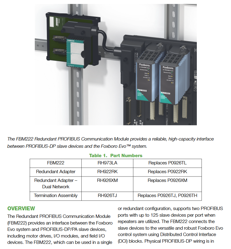
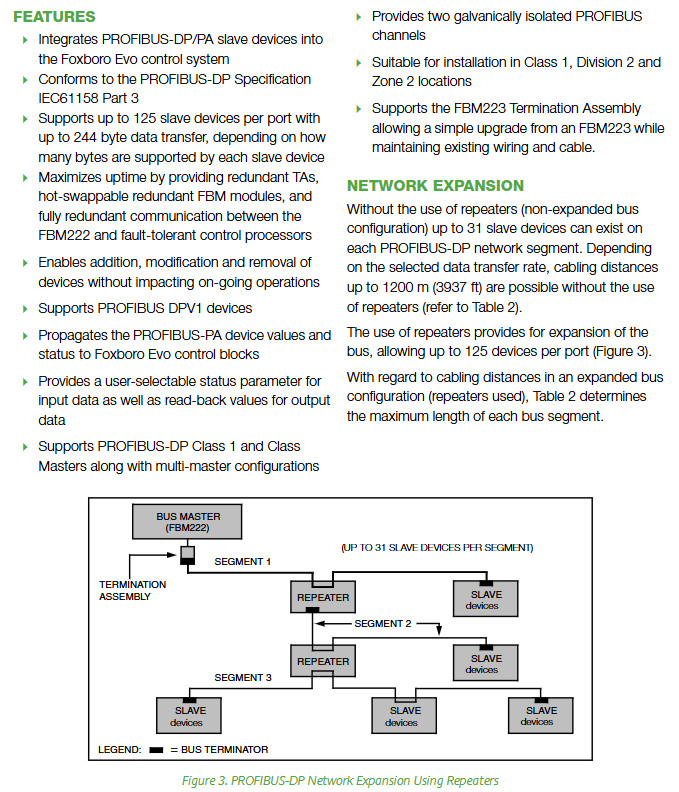
FBM222 is a 16 channel highly integrated analog input module with core functionality for Foxboro ™ The I/A Series distributed control system (DCS) collects 4-20mA analog signals on site (supporting two-wire/three wire transmitters), while using HART ® The protocol (digital communication superimposed on 4-20mA signal) enables bidirectional data exchange with on-site devices (such as reading device diagnostic information and configuring parameters). It is positioned as a “high-density, high reliability analog signal+HART digital signal integrated acquisition center”, suitable for the needs of batch collection of sensor/transmitter data in industrial scenarios such as petroleum, chemical, and power.
1. Core functions and compatibility
Dual compatibility of signals: All 16 channels support “4-20mA analog signal” and “HART ® Digital signals “can be mixed and connected to different types of on-site devices (without the need for additional hardware switching).
HART communication capability: As a HART host, it supports HART protocol v5/v6/v7 version devices and can execute HART universal commands, common commands, and device specific commands (with Field Device Expert for HART tool), but does not support HART burst mode.
Basic adaptation requirements: It is necessary to use I/A Series software v8.2-v8.8 or Control Core Services (CCS) v9.0 or above, and connect to the Fieldbus communication module (FCM) or control processor (FCP) through a redundant 2Mbps fieldbus to achieve data upload and instruction issuance.
Power supply flexibility: Supports “internal module power supply” (providing 24VDC power supply for two-wire transmitters) or “external independent power supply” (compatible with three wire devices), and signal crosstalk needs to be suppressed through Cable Balun modules when external power is supplied.
Key features and technological advantages
1. Core Features
Specific description of characteristic categories
Full isolation protection achieves triple isolation: 16 channels are isolated from each other, channels are isolated from module logic circuits, and channels are isolated from ground. It can withstand 600VAC common mode voltage for 1 minute (without damage), completely avoiding signal interference and equipment burnout risks.
High precision acquisition adopts Sigma Delta (∑ – Δ) analog-to-digital converter, with a data update cycle of 100ms per channel. The accuracy of analog acquisition meets the industry’s high standards, meeting the requirements of process control for real-time and accurate data.
The harsh environment adaptation shell is made of extruded aluminum material, which meets the Class G3 (harsh industrial environment) requirements of ISA S71.04 standard. It can withstand complex scenarios such as dust, humidity fluctuations (5% -95% non condensing), and sudden temperature changes (-20~70 ℃).
Hot swappable and easy to maintain support “with hot swappable”, allowing for module replacement without disconnecting field wiring, power supply, or communication bus; The front of the module is equipped with LED indicator lights (running status, bus activity, channel communication status), which can intuitively locate faults.
Communication redundancy ensures access to a redundant 2Mbps fieldbus (A/B dual path), which automatically switches to the backup path in case of a single path failure without communication interruption, ensuring data collection continuity.
2. Special component: Cable Balun module
When multiple channels are powered by an external common power source, a Cable Balun module is required to maintain the balance of the HART communication line and prevent near end crosstalk (this component is not required for internal power supply channels). The core parameters are as follows:
Specific specifications of component information
Model CBM-4
Part number RH903SV
Each module contains 4 Balun units (1 unit corresponds to 1 external power supply circuit), with a maximum increase of 30 Ω in circuit resistance to suppress signal interference
If the hazardous environment adaptation is used in hazardous areas (such as Zone 2), it is necessary to use intrinsic safety barriers (such as MTL 787S+) to limit the energy of the line; External power sources can be connected in parallel with redundant power sources. It is recommended to use capacitors to filter out AC interference
Functional and Performance Specifications
1. Signal and communication parameters
Parameter category specific specifications
HART device compatibility supports HART ® On site devices for protocol v5, v6, and v7 versions
Internal power supply of input resistor (including terminal components): 302 Ω; External power supply: 282 Ω
Internal power supply output 24VDC ± 10%, output impedance 20 Ω (including terminal components), single channel current limit < 37mA (anti overcurrent)
Fieldbus communication redundancy of 2Mbps, bidirectional communication with FCM/FCP, with a maximum communication distance of 1.2km (without repeaters)
Channel capacity of 16 independent analog input channels, supporting mixed access of two-wire/three wire devices
2. Power supply and power consumption
Power parameter specifications
Input voltage 24VDC (redundant power supply), allowing+5%/-10% fluctuation
Maximum power consumption 10.8W
Maximum heat dissipation 7.2W
3. Calibration requirements
The precision calibration of the module and supporting terminal components (TA) has been completed at the factory, and there is no need for regular on-site calibration, greatly reducing maintenance workload (only confirming basic parameters after module failure replacement).
Hardware and installation specifications
1. Core hardware components
Component type, model/part number, key parameters
FBM222 module RH927AJ weight: approximately 340g (12oz); Dimensions: Height 102mm x Width 114mm (including installation ears) x Depth 104mm
Terminal component (TA) RH924JH material: polyamide (PA, temperature resistance -20~70 ℃); Wiring type: compression terminal; Weight: Approximately 181g (0.40lb); Adapt to 16 channel signal access
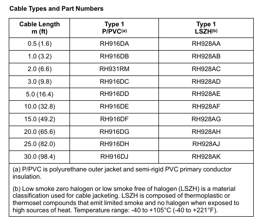
Terminal cables are divided into two types of materials:
-Polyurethane/PVC (Type 1 P/PVC): suitable for conventional industrial environments;
-Low Smoke Zero Halogen (Type 1 LSZH): Suitable for scenarios with requirements for smoke toxicity and corrosiveness (such as subways, data centers)
The module installation needs to be installed on a 200 series standard modular base plate (such as RH101KF), which supports horizontal/vertical DIN rail installation or can be adapted to a 19 inch rack through an installation kit; Can be installed on the same substrate as other 200 series FBM modules
TA can be installed independently on 32mm or 35mm DIN rails, and can be installed in the same cabinet or adjacent cabinets with the module (the terminal cable supports a maximum length of 30m)
The wiring specifications support solid/multi strand wires (wire diameter 0.2~4mm ²/24~12AWG), and multi strand wires with wire ears (wire diameter 0.2~2.5mm ²) can also be adapted
Temperature -20~70 ℃ (-4~158 ℉) -40~70 ℃ (-40~158 ℉)
Relative humidity 5%~95% (no condensation) 5%~95% (no condensation)
Altitude operation: up to 3000m; storage: -300~12000m
The anti pollution level complies with ISA S71.04 Class G3 and has passed the EIA 364-65A Class III mixed gas exposure test (withstanding a corrosive environment for 10 years)
Anti vibration 0.75g (frequency 5-500Hz)-
2. Compliance certification
Specific standards for certification categories
Electromagnetic compatibility (EMC) complies with EU Directive 2014/30/EU, EN 61326-1:2013 Class A (Emission and Industrial Immunity)
Product Safety – USA/Canada: UL/UL-C certification, applicable to Class I A-D Group 2, T4 temperature code cabinet systems;
-EU: Low Voltage Directive 2014/35/EU, ATEX Directive 2014/34/EU (DEMKO certified Ex nA IIC T4, suitable for Zone 2 hazardous environments)
International Safety IECEx Certification (compliant with IEC 60079 series standards)
Environmental compliance complies with the EU RoHS Directive 2011/65/EU and revised versions 2015/863, 2017/2102 (restricting the use of hazardous substances)
California Proposition 65 products contain lead and lead compounds, which may cause cancer or reproductive harm. For more information, please refer to www.P65Warning.ca.gov
Terminal Cable Selection Table
Terminal cables are classified by material and length, and commonly used specifications are as follows (can cover installation distances of 0.5-30m):
Length (m/ft) Type 1 Polyurethane/PVC Cable (Part Number) Type 1 Low Smoke Zero Halogen (LSZH) Cable (Part Number)
FBM214b is an 8-channel independent isolated analog input module, with the core function of implementing Foxboro ™ DCS and “Standard 4-20mA Analog Equipment” and “HART ® The bidirectional communication and data acquisition of protocol digital devices can be compatible with mixed access of two types of devices without additional hardware. It is positioned as an integrated acquisition center for analog signals and HART digital signals, suitable for industrial scenarios that require simultaneous acquisition of device analog and digital diagnostic information (such as sensor and transmitter data acquisition in process control).
Core functions
Signal compatibility: All 8 channels support two types of input signals and can be mixed and configured
Standard 4-20mA analog sensor signal;
HART superimposed on 4-20mA analog signal ® Frequency Shift Keying (FSK) digital signal.
HART communication capability: As the host of HART field devices, it can receive 2 digital messages per second from the field devices, supporting HART universal commands, common commands, and device specific commands (which need to be implemented through Foxboro DCS Field Device Expert for HART tool), but does not support burst communication mode.
Power supply flexibility: Each channel is equipped with an independent isolated power supply, which can be powered internally or externally (when using an external power supply, a Cable Balun module is required to prevent crosstalk).
Basic compatibility: It needs to be compatible with I/A Series software v8.2-v8.8 or Control Core Services v9.0 or above, and connected to the Fieldbus Communication Module (FCM) or Control Processor (FCP) through a redundant 2Mbps fieldbus.
Key features and technological advantages
1. Core Features
Specific description of characteristic categories
Isolation protection is achieved between 8 channels, between channels and ground, and between channels and module logic circuits, with * * galvanic isolation (electrical isolation) * *. It can withstand 600VAC common mode voltage for 1 minute (without damage), avoiding signal interference and equipment damage.
High precision acquisition uses Sigma Delta (∑ – Δ) converters, with analog input values updated every 100 milliseconds for each channel to ensure data acquisition accuracy.
The environmental adaptability shell is made of extruded aluminum material, which is suitable for harsh environments and meets the * * Class G3 (harsh) environmental * * requirements of ISA standard S71.04. It supports industrial scenarios such as dust and humidity fluctuations.
Maintenance convenience supports “hot plugging”, which means that when replacing modules, there is no need to disconnect on-site wiring, power or communication cables; The front LED indicator light can visually display the module’s operating status and channel communication activity.
Redundant access to 2Mbps fieldbus (A/B dual path), automatically switches to another path in case of a single path failure, ensuring uninterrupted communication.
2. Special component: Cable Balun module
When multiple channels are powered by an external common power source, a Cable Balun module is required to maintain the balance of the HART communication line and prevent near end crosstalk (this module is not required for internal power supply channels). The core parameters are as follows:
Specific specifications of component information
Model CBM-4
Part number RH903SV
Each module contains 4 Balun units, with 1 unit corresponding to 1 external power supply circuit. The maximum increase in circuit resistance is 30 Ω
Installation requirements require the use of intrinsic safety barriers (such as MTL 787S+) to limit line energy in hazardous environments; External power supply can be connected in parallel with redundant power supply. It is recommended to cross connect the capacitor provided by the user to filter out AC power
Fieldbus communication redundancy 2Mbps fieldbus, bidirectional communication with FCM/FCP
2. Power supply and power consumption
Power parameter specifications
Input voltage (redundant) 24VDC, allowing+5%/-10% fluctuation
Maximum power consumption 8.4W
Maximum heat dissipation 5.6W
3. Calibration requirements
Modules and terminal components (TA) do not require regular calibration, and precision calibration has been completed at the factory, reducing maintenance workload.
Hardware and installation specifications
1. Core hardware components
Component type, model/part number, key parameters
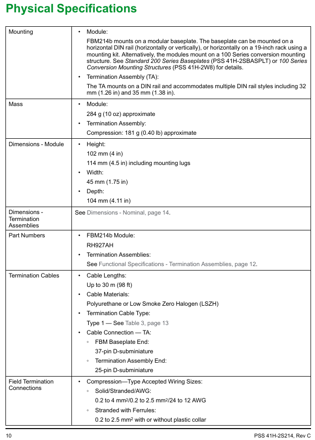
FBM214b module RH927AH weight: approximately 284g (10oz); Dimensions: Height 102mm x Width 114mm (including installation ears) x Depth 45mm (or Depth 104mm, depending on configuration)
Terminal Component (TA) RH924JH Material: Polyamide (PA, -20~70 ℃ temperature resistance); Wiring type: compression terminal; Weight: Approximately 181g (0.40lb)
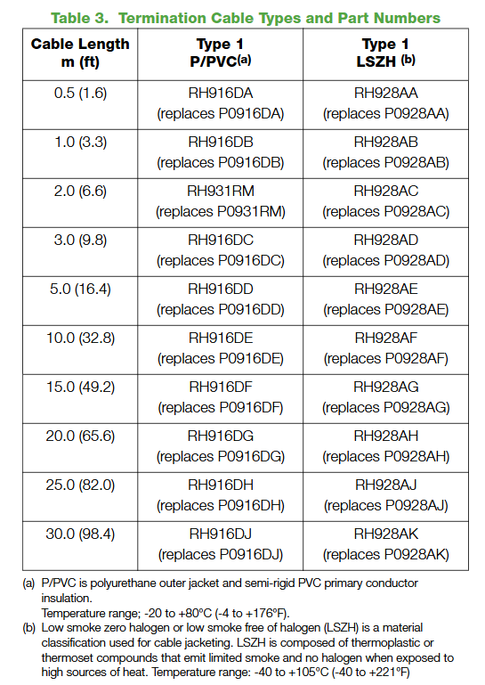
Terminal cables are made of two materials (polyurethane/PVC, low smoke halogen-free LSZH), with a length of 0.5-30m (1.6-98ft), such as RH916DA (0.5m polyurethane) RH928AA(0.5m LSZH)
The module installation needs to be installed on a modular base plate, which supports horizontal/vertical DIN rail installation or can be adapted to a 19 inch rack through an installation kit; It can also be installed on the 100 series conversion installation structure (refer to PSS 41H-2W8)
TA is installed on 32mm or 35mm DIN rails and can be installed in the same cabinet or adjacent cabinets as the module (with a maximum cable length of 30m)
Wiring specifications support solid/multi strand wires (0.2~4mm ²/24~12AWG), multi strand wires with wire ears (0.2~2.5mm ², compatible with or without plastic sleeves)
The anti pollution level complies with ISA S71.04 Class G3 and has passed the EIA 364-65 Class III exposure test-
Anti vibration 0.75g (5~500Hz)-
2. Compliance certification
Specific standards for certification categories
Electromagnetic compatibility (EMC) complies with EU directives 2004/108/EC (before April 20, 2016), 2014/30/EU (after April 20, 2016), and meets EN61326-1:2013 Class A (emission and industrial immunity)
Product Safety – UL/UL-C Certification in the United States/Canada: Suitable for cabinet systems with Class I A-D Group 2, T4 temperature code;
-EU Low Voltage Directive 2006/95/EC (before April 20, 2016), 2014/35/EU (after April 20, 2016);
-EU ATEX Directive 94/9/EC (before April 20, 2016), 2014/34/EU (after April 20, 2016): DEMKO certified Ex nA IIC T4 for Zone 2 hazardous environments
Environmental compliance complies with the EU RoHS Directive 2011/65/EU and revised versions 2015/863, 2017/2102
International Certification IECEx Certification
California Proposition 65 products contain lead and lead compounds, which may cause cancer or reproductive harm. For more information, please refer to www.P65Warning.ca.gov
Terminal Component (TA) and Cable Configuration
1. TA core parameters (RH924JH)
Specific specifications for TA
Adapt signal 8-channel 4-20mA analog signal/HART digital signal
Authentication Type 1+Type 2 Dual Authentication:
-Type 1: UL/UL-C Class I A-D Group 2 T4, ATEX Ex nA IIC T4 2;
-Type 2: UL/UL-C associated equipment (non flammable field circuit), ATEX IIC Zone 2 associated equipment, meets Class 2 current limiting requirements (below 60VDC/30VAC/100VA)
2. Terminal cable selection
Cables are divided into two categories: “Polyurethane/PVC (Type 1 P/PVC)” and “Low Smoke Zero Halogen (Type 1 LSZH)”. The latter is suitable for scenarios that require smoke toxicity and corrosiveness (such as subways and data centers). The commonly used lengths and part numbers are as follows:
Length (m/ft) Type 1 P/PVC Part Number Type 1 LSZH Part Number
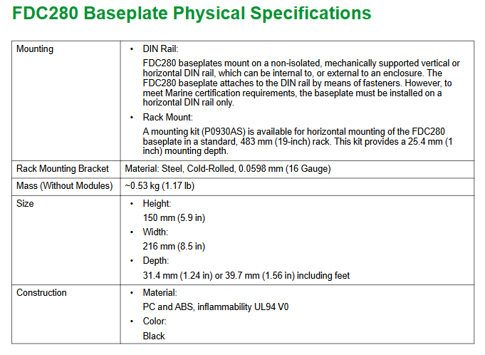
FDC280 is a distributed and optional fault-tolerant on-site installation controller, with the core function of implementing Foxboro ™ The integration of DCS and field devices does not require additional fieldbus modules (FBM), and it also undertakes process control and alarm tasks. It is mainly positioned as the “field device integration center”, which is different from the same type of FCP280 (which does not support PIO bus and focuses on Ethernet/serial protocol integration).
1. Core functions
Device integration: Directly interface with Ethernet/serial field devices that support multiple protocols, collect device data for display, historical storage, and execute control tasks.
Control capability: Built in adjustment control, logic control, timing control, sequence control functions, supporting alarm detection and notification.
Hardware architecture: Adopting dual core ARM ® SOC processor with clear dual core division of labor:
Core 1 (Control Core): Run control software and DCS control network communication software, supporting fault-tolerant operations.
Core 2 (I/O core): Run device integration software, independently handle on-site device connections and status diagnostics.
Basic requirements: A host workstation with Foxboro DCS Control Core Services v9.3 or higher must be installed, and connected to the control network via 100Mbps fiber/copper Ethernet. It must have obtained ISASecure EDSA Level 1 security certification.
2. Key difference: FDC280 vs FCP280
Comparison item FDC280 FCP280
Core positioning on-site equipment integration (Ethernet/serial port) universal process control
PIO bus support not supported
Core advantage: No FBM required, directly integrated with field devices compatible with traditional PIO bus devices
Network configuration plan
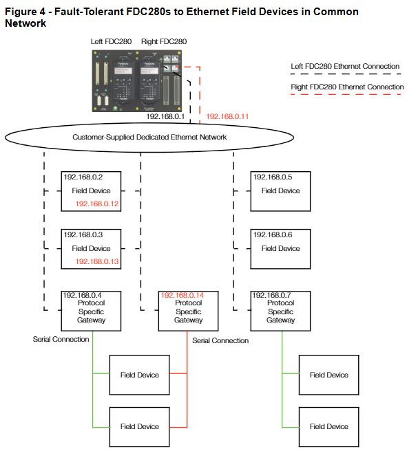
FDC280 supports both Ethernet and serial network configurations, divided into two modes: “simplex” and “fault tolerant”, to meet the redundancy requirements of different field devices.
1. Ethernet network configuration
Support direct connection to Ethernet field devices or connection to serial devices through a “protocol specific gateway” (to achieve Ethernet serial bridging), with three core solutions:
Configuration Type Applicable Scenarios Key Features
Simplex, a single FDC280 module for scenarios with low reliability requirements, does not require redundant connections and saves wiring costs
Fault tolerant – Independent network with high reliability requirements, on-site equipment requires independent redundant network dual FDC280 modules (left/right), connected to two independent Ethernet networks provided by customers, with module IP addresses that can be the same or unique
Fault tolerant – Shared network field devices without independent redundancy requirements (such as single port devices). Dual FDC280 modules share one Ethernet network, supporting single port device access and reducing network complexity
Note: It is recommended to use a management switch for easy maintenance and troubleshooting; The device can also be directly connected to the FDC280 motherboard without the need for a switch.
2. Serial port network configuration
Each module of FDC280 contains 4 independently configurable serial ports (supporting RS232/RS422/RS485), with a maximum support of 128 serial field devices (up to 32 devices per RS485 port). The core solution is divided into 2 types:
Non fault-tolerant (Simplex): A single FDC280 can be connected to a single port serial device through a “Terminal Component (TA)”, supporting RS485 multi station connection without a modem and RS232/RS422 direct connection.
Fault tolerant type: Dual FDC280 modules are connected to devices through TA and adapted to different port devices:
Dual port device: The left/right module connects the two ports of the device separately to achieve redundant communication.
Single port device: RS232 needs to be connected to two TAs through a Y-shaped cable; RS485/422 can be directly connected through a dual module TA sharing connection.
Core features and performance parameters
1. Key functional characteristics
Specific description of characteristic categories
The device and I/O capacity support a maximum of 256 field devices, 8000 soft I/O points, and 8252 total functional blocks (including Station blocks, ECB components, etc.). Please refer to the FDC280 sizing tool (B0700GS) to calculate the load
The protocol supports 6 core protocols, some of which support concurrent multi instance/multi version (see table below for details)
The diagnostic capability has a built-in “diagnostic driver” that can capture real-time communication messages with the device and send them to the workstation diagnostic application without physical interruption
Fault tolerance mechanism dual module “marriage” operation, Control Network communication requires dual module messages to be matched bit by bit before sending; Core 1 supports primary/backup switching, while Core 2 supports redundancy state comparison and role handover
In self hosted mode, the control database checkpoint file is stored in flash memory, and the host can autonomously start and execute control policies when offline
Software updates distinguish between “Major updates (new features, no online upgrade support)” and “Minor updates (only module switching, no process interruption)”
Environmental adaptability die-casting aluminum shell, no need for ventilation, supports Class G3 harsh environment (ISA S71.04 standard), CE certification for on-site installation
Time synchronization supports GPS satellite UTC time (external) or DCS internal TimeKeeper synchronization (internal), with data timestamp accuracy of 10 times/second (minimum scanning interval of 100ms)
2. Support protocols and concurrency capabilities
Protocol name, part number, multiple protocols, concurrent support, same protocol, multiple instances support
Modbus TCP Client K0177AH Yes Yes
Modbus RTU&ASCII Client K0177CV Yes
Triconex ™ TSAA Client K0177DE is
OPC UA Client K0177EC (single instance only)
Is EtherNet/IP Scanner Driver K0177EP
PROFINET IO Controller K0177FU No No (single instance only)
3. Functional specification parameters
Specific numerical values for parameter categories
The maximum execution speed of functional blocks with a processor performance of 16000 blocks per second, and the minimum block processing cycle (BPC) of 100ms
The maximum capacity of a single sequence block is 32KB
IPC connects 200 data source points (providing external data), 30 sink points (receiving external data), and 1 dedicated internal point
OM (Object Manager) can scan a database with a maximum capacity of 28000 points (18000 points when BPC ≥ 200ms, 7500 points when BPC=100ms); The maximum convergence point is 11250 points
Configurable block period of 0.1/0.2/0.5/0.6/1/2/5/6/10/30 seconds, 1/10/60 minutes
Fault tolerant module pairing time is less than 0.5 seconds
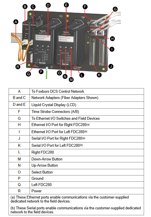
Hardware and environmental specifications
1. Core hardware components and parameters
The FDC280 hardware includes four categories: “module”, “motherboard”, “network adapter”, and “terminal component”. The key parameters are as follows:
FDC280 module RH101FQ size: height 105/116mm (including installation ears) x width 51.8mm x depth 147mm; single module weight 0.8kg
The base plate RH101KF (2 bits) supports 1 non fault tolerant module or 2 fault tolerant modules, including 2 10/100Mbps/1Gbps copper cable Ethernet RJ45 interfaces, 2 37 pin D-type serial port interfaces, and 2 time synchronization interfaces
Network adapter fiber optic: RH924WA (Rev. E+); Copper cable: RH924UQ (Rev. D+) takes power from the base plate, fiber supports multimode 62.5/125 μ m cable (maximum 2km), copper cable supports Cat5 (maximum 100m)
Serial terminal component ring terminal post: P0926PA; Tightening screws: RH926GH weighs 363g and 272g respectively, and needs to be paired with Type 5 terminal cables (such as RH100HV-1m and RH100HZ-5m)
2. Power and environmental requirements
Category specifications
Power requirement input voltage: 24VDC (redundant,+5%/-10%); The maximum power consumption of a single module is 8.5W
Working temperature -20~60 ℃ (-4~140 ℉)
Storage temperature -40~70 ℃ (-40~158 ℉)
Relative humidity 5%~95% (no condensation)
Altitude operation: up to 3000m; storage: -300~12000m
Anti pollution level Class G3 (ISA S71.04), supports 10-year mixed gas exposure testing (EIA 364-65A Class III), module with conformal coating (conformal coating: protective coating)
Vibration resistance 0.5g (5~500Hz)
3. Compliance certification
Electromagnetic Compatibility (EMC): Compliant with Directive 2014/30/EU, EN 61326-1 Class A (Emission and Industrial Immunity).
Product safety: UL/UL-C certification (applicable to Class I, Groups A-D, Zone 2), EU Low Voltage Directive (2014/35/EU), ATEX Directive (2014/34/EU, DEMKO Ex nA IIC T4 Gc, applicable to Zone 2).
Environmental compliance: Compliant with the EU RoHS Directive (2011/65/EU and revised versions 2015/863, 2017/2102).
California Proposition 65: Products containing lead and lead compounds may cause cancer or reproductive harm, details can be found at www.P65Warning.ca.gov.
Fault tolerance mechanism and reliability design
The “fault-tolerant” core of FDC280 consists of dual module redundancy, independent diagnosis, and seamless switching, covering the control network, CPU, and I/O levels to ensure uninterrupted processes
The dual modules of the control network are connected through the backplane and share control network access (dual switches). Communication messages need to be matched bit by bit by the dual modules before being sent. When a fault is detected, the non faulty module takes over control without process interruption
Core 1 (control core) primary/backup mode, real-time synchronization status. When the primary core fails, the backup core immediately switches to primary dynamic mode
Core 2 (I/O core) independently diagnoses the connection status of dual core devices. When the main core fails and the backup core device is better connected compared to the backup core status, the main core resets and hands over the role
The main module on the I/O side is responsible for reading and writing I/O points, while the backup module monitors device connections through “heartbeat commands” and synchronizes I/O values in real-time. When the main module loses connection, the backup module seamlessly takes over without any process fluctuations
2. Maintain convenience
Hot plug support: Replacing the FDC280 module does not require disconnecting the backplane power supply, and does not affect the field I/O signal of another module.
Status visualization: The front of the module includes an LCD display screen (displaying module identification, role, hardware version, network status) and LED indicator lights (running status, Ethernet connection status), supporting the configuration of “letterbug” through panel buttons.
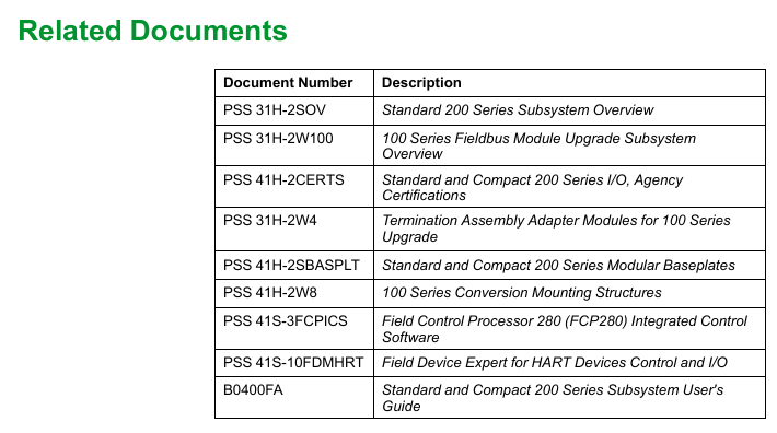
Related documents and support
For further technical details, please refer to the following supporting documents:
Document Number Document Name Purpose
B0700GQ “FDC280 User Guide” Installation, Configuration, and Operation Guide
B0700GS “FDC280 sizing tool and Excel workbook guide” for calculating processor load and functional block capacity
PSS 41H-2SBASPLT “200 Series Standard Base Plate Specification” Base Plate Installation and Interface Instructions
PSS 41S-1TIME “Overview of DCS Time Synchronization” Time Synchronization Configuration and Accuracy Description
PSS 41S-3xxx protocol driver specifications (such as 41S-3FDCMBDV for Modbus TCP driver) specific protocol integration parameters