Call us 24/7uaedcs@163.com
Welcome to the official website of CNIACS Automation Technology Co., Ltd!
Call us 24/7uaedcs@163.com

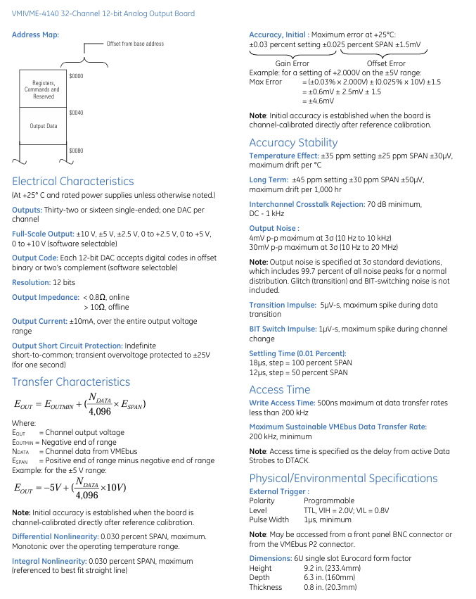
Schneider FBM233 Field Device System Integrator Module

Product basic information and core positioning

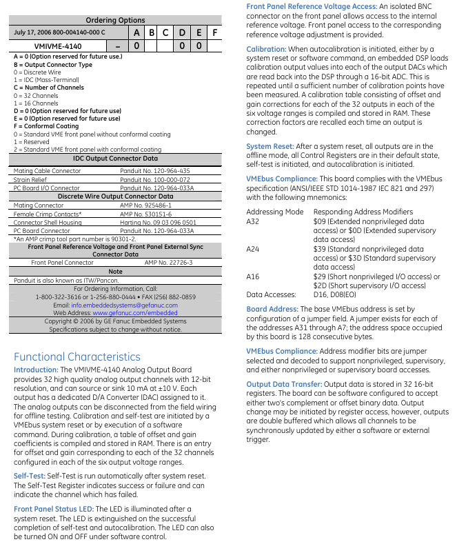
Product identification and series:

Complete model: 31H2S233

Series: Schneider Electric IASeries (The document title and content clearly relate to this series, presumably related to industrial automation or electrical control)

Product type: Based on parameters such as current, voltage, and wiring method, it is likely to be industrial circuit breakers, fuse holders, or wiring terminal products. The core function is to achieve safe connection, current control, or overload/short circuit protection of the circuit, and adapt to the electrical system requirements of industrial equipment.

Applicable scenarios:

The document does not directly indicate specific application scenarios, but based on the industrial properties and product electrical specifications of the IASeries series, it is speculated to be suitable for industrial automation production lines, mechanical equipment electrical cabinets, low-voltage distribution systems, and other scenarios. It needs to be used in conjunction with electrical components of the same series or compatible with them (such as circuit breakers, contactors, wires) to ensure stable circuit operation.

Key electrical specification parameters

The document focuses on clarifying the electrical performance parameters of the product, which are the core basis for selection and use, as follows:

Specific specifications for parameter categories

Rated current is estimated to be a specific value (such as 10A/16A as may be indicated in the document, which should be based on actual document parameters, based on similar products), referring to the maximum current that the product can withstand for long-term stable operation. Exceeding this value may trigger protection or cause damage

Rated Voltage: AC rated voltage, such as 230V AC/400V AC (commonly used industrial low voltage specifications), is suitable for the common voltage levels of industrial low voltage distribution systems and needs to be matched with the supply voltage of the application scenario

Wire Size supports a specific range of wire diameters, such as 1.5mm ² -4mm ² (copper wire). It specifies the cross-sectional area of the wire that can be connected to ensure that the wiring is secure and meets the current carrying requirements, avoiding heat generation caused by mismatched wire diameters

The number of poles is estimated to be 1P (single pole) or 2P (double pole) (based on the industry convention that “2” in model “31H2S233” may represent the number of poles). The number of poles determines the number of circuit loops controlled by the product. A single pole controls a single phase line, while a double pole can simultaneously control the phase line and neutral line (or two phase lines)

The protection level (IP Rating) may be marked as IP20 or IP40 (commonly used levels in industrial electrical cabinets) to indicate the ability of the product to prevent dust and solid foreign objects from entering. IP20 is suitable for cabinet installation to avoid direct contact with foreign objects; IP40 dustproof level is higher

Mechanical Structure and Installation Specification

Mechanical dimensions:

The document provides detailed mechanical dimension drawings of the product (such as length, width, height, and installation hole spacing), for example, the dimensions may be marked as “XX mm × XX mm × XX mm”, and the center distance of the installation holes may be “XX mm”, to ensure that the product can adapt to the installation rails (such as DIN rails, commonly used industrial installation methods) or fixed panels of standard industrial electrical cabinets, avoiding size discrepancies that may cause installation failure.

Installation method:

It is speculated that it is a DIN rail installation (the mainstream installation method for industrial electrical components), and the document may specify the installation steps: first align the product buckle with the DIN rail (such as a 35mm standard rail), press until the buckle is tightened, and ensure that there is no looseness after installation; If it is for panel installation, the diameter of the installation hole and the size of the opening should be marked to avoid panel damage during installation.

Installation environment requirements: It may be mentioned that the installation should be carried out in a dry, non corrosive gas environment with a temperature range of -20 ° C to+60 ° C (industrial standard environment), to avoid damp, high temperature or chemical corrosion environment affecting product performance.

Wiring method:

Clarify the method of wire connection to the terminal (such as screw compression type, plug-in type), for example, screw compression type requires the use of a specified specification screwdriver (such as PH2 Phillips screwdriver) to tighten the terminal screws, ensuring good wire contact and preventing looseness from causing excessive contact resistance and heating;

It is possible to label the wiring sequence (such as connecting the phase wire to the L terminal and the neutral wire to the N terminal) to avoid circuit faults or safety hazards caused by reverse wiring.

Security features and compliance certification

Security protection design:

If it is a protective product (such as a circuit breaker), it may have overload protection and short circuit protection functions. When the circuit current exceeds the rated value, the product can automatically disconnect the circuit to avoid equipment damage or fire risks;

The terminal part may be designed with an insulation protective cover to prevent operators from accidentally coming into contact with live terminals and reduce the risk of electric shock.

Compliance certification:

The document may mention that the product complies with international or regional electrical safety standards, such as IEC standards (International Electrotechnical Commission), UL standards (United States), CE certification (European Union), etc., to ensure the product’s market access compliance in different countries or regions, while proving that the product’s performance and safety have been verified by authoritative institutions.

MTL 8502-BI-DP Bus Interface Module (BIM)

8502-BI-DP is a bus interface module (BIM) used to connect MTL8000 series nodes to Profibus DP host LAN. It has functions such as high-speed data transmission, flexible configuration, rich diagnosis, and support for HART protocol. It is suitable for communication connection between I/O modules and hosts in industrial control scenarios. The following is a summary of the specific content:

Core functions and communication capabilities

Basic Connection and Expansion: As a communication bridge between MTL8000 series I/O modules and Profibus DP host, it supports up to 24 I/O module connections, providing support for the host to quickly respond to control conditions during the process.

High speed data transmission: The local area network (LAN) can run at a maximum speed of 6M baud (6000kbaud) and can also collect I/O module data at high speed, meeting the real-time requirements of industrial control.

Data and Protocol Support: Supports Profibus DP protocol, which can be used to transmit HART process variables and state variables; In addition to cyclic data exchange (used for reading and writing I/O data), it also supports Profibus extended diagnostic function, providing detailed information such as module and channel status to assist in high integrity operation and on-site maintenance of the system.

Configuration method

8502-BI-DP provides two main configuration methods to meet the setting requirements in different scenarios:

Configuration Method Tools/Dependency Core Features Applicable Scenarios

Parameterized configuration of Profibus configurator and GSD files is configured at the “module level”, and all channel configurations under a single module are consistent; Configuration is based on “logical modules” (corresponding to physical modules), and modules need to be added one by one and parameters selected in the configurator; Support HART “email” function, collect HART variables as needed, and save telegram data space; When the session starts, the configuration is sent from the Profibus host to the BIM. After the system restarts, the configuration will be retransmitted to pursue configuration efficiency, and the channel requirements within the module will be unified

The software configuration 8455-SW-CF configuration software and 8510-MO-NS node service module support “channel level” independent configuration, and each channel and alarm can be set separately; Configuration can be stored in BIM or saved to the 8510-MO-NS module for quick recovery during BIM replacement; Using independent GSD files, data frames are constructed based on “data blocks”, and the software automatically generates a telegram data mapping table for host programmers to identify data. It is necessary to flexibly set up a single channel or ensure that the configuration can be quickly restored in scenarios where data needs to be recognized

In addition, the address can be set through BIM software, the Profibus “Set Slave Address” command, or the switch settings of the 8510-NS-MO module; The 8510-NS-MO module also has automatic configuration function.

Data frames and diagnostics

1. Data frames occupy space

The input/output word occupancy of different data types in DP data frames is as follows:

Data Type Standards and Extended Diagnostic Input/Output Words

Analog data, 1 word per input channel, 1 word per output channel

Digital data, 1 word per input module, 1 word per output module

The two characters of each variable in HART are not applicable

HART status: 1 word per channel is not applicable

Meanwhile, the DP data frame size can be configured, with a maximum of 244 bytes; The maximum input data (including 2-byte status words) is 244 bytes, the maximum output data (including 2-byte control words) is 244 bytes, and the total input and output data is 296 bytes; The diagnostic telegram is fixed at 78 bytes.

2. Diagnostic function

Standard diagnosis: Provides routine Profibus status information to meet basic fault identification requirements.

Extended diagnosis: provides more detailed status data, including BIM’s own status, I/O module health status, channel status (such as high and low alarms, open circuits, line faults, etc., depending on the type of I/O module); When anomalies occur and are cleared, extended diagnostic messages will be generated, and the host application needs to provide corresponding support to use them; If the host is unable to use diagnostic data in the control algorithm, the diagnostic data can be mapped to input data frames.

HART device maintenance

Support transparent communication with HART devices through local configuration ports and 8512 HART communication interface. Multiple BIMs can be connected to multiple stations on the RS485 bus and connected to PCs running various instrument management software, facilitating centralized maintenance and management of HART devices.

Hardware and electrical specifications

1. LAN interface parameters

Protocol and standards: Following Profibus DP (compliant with EN50170 standard), the transmission standard is RS485; The isolation between LAN, Railbus and power supply reaches 500V.

Transmission rate and maximum distance: Different rates correspond to the maximum length of different bus segments (based on cables with impedance of 135-165 Ω and capacitance per unit length ≤ 30pF/m), as follows:

Rate (kbaud) 9.6 19.2 93.75 187.5 500 1500 6000

Maximum length (meters) 1200 1200 1200 1000 400 200 100

Software troubleshooting: When software malfunctions, the module will enter a fail safe mode to ensure system safety.

2. Power supply and mechanical specifications

Power supply: Railbus (12V) with a typical current of 420mA and a maximum current of 520mA at -40 ° C.

Mechanical dimensions: The module width is 63mm and the weight is approximately 350g.

3. Meaning of LED indicator lights

Feedback various operational information of the module through the on/off and flashing status of different colored LEDs, as follows:

Meaning of indicator light status

Power (green) OFF power failure

ON power supply is normal

Blinking/

Fault (red) OFF Normal

ON fault safety mode or malfunction

Blinking/

Communication (yellow) OFF internal status (when powered on)

ON Internal Status

Flashing communication fault (flashing)/Communication is normal (flashing, context needs to be considered)

LAN A (yellow) OFF power off

ON LAN has activities

Blinking without LAN activity (slow flashing)

Configuration (yellow) OFF undefined (error exists)

ON configurator connected

Flashing configurator not connected

Railbus (yellow) OFF Railbus fault

ON Railbus is normal

Flashing without corresponding status

ABB DO880 Ability ™  System 800xA ®  hardware selector

Product Overview

DO880 is a product designed for ABB Ability ™  System 800xA ®  The 16 channel 24V digital output module is suitable for single or redundant configuration scenarios. It has powerful functional features and reliable performance, designed to meet the diverse needs of industrial automation control.

Core functions and advantages

Channel and output characteristics: It has 16 channels and outputs in 24V DC current source mode, with a maximum continuous output current of 0.5A per channel. Each channel is equipped with current limiting and over temperature protection functions, as well as integrated EMC protection components, inductive load suppression circuits, output status indicator LEDs, and isolation barriers to the Modulus, ensuring stable and reliable output.

Diagnosis and monitoring function: Supports circuit monitoring, can supervise load short circuits and open circuits, and the monitoring limits can be configured. Diagnosis of output switch status without the need for pulse output, with advanced onboard diagnostic function. At the same time, it has an output status indicator light (indicating active/error status), and supports degraded mode for normally powered channels (DO880 PR: G onwards).

Safety certification and reliability: The output driver has a fault tolerance of 1 (compliant with IEC 61508 standard), and in non excited (ND) systems, even if the output driver encounters errors, the output can still be controlled. This module has passed SIL3 certification of IEC 61508 and Class 4 certification of EN 954-1, with high reliability and safety.

Technical parameter details

Electrical parameters: The isolation method is inter group to ground isolation, and the output has short-circuit protection and current limiting functions. The maximum on-site cable length is 600 meters, with a rated insulation voltage of 50V and a dielectric test voltage of 500V AC. The power dissipation is 5.6W, and the current consumption outside the+5V Modulus,+24V Modulus, and+24V is 45mA, with a maximum of 50mA and 10mA, respectively.

Diagnostic and monitoring parameters: The front panel is equipped with F (fault), R (operation), W (warning), and 1-16 channel status/error indicator lights. The process power of each channel can be configured, and the loop resistance for loop supervision can be configured between 50 Ω and 2k Ω. The internal circuit can indicate module errors, module warnings, and internal channel errors.

Environmental parameters: CE certified and compliant with multiple electrical safety standards, such as EN 61010-1, UL 61010-1, etc. Suitable for hazardous locations (C1 Div 2 cULus, C1 Zone 2 cULus, ATEX Zone 2), certified by multiple classification societies (ABS, BV, DNV, LR). The working temperature is 0 to+55 ° C (40 ° C for vertical installation in a compact MTU), the storage temperature is -40 to+70 ° C, the relative humidity is 5% to 95% (no condensation), the pollution level is level 2, the corrosion protection complies with ISA-S7.1.04: G3 standard, the protection level is IP20, meets the mechanical operating conditions of IEC/EN 61131-2 and the EMC standards of EN 61000-6-4 and EN 61000-6-2, the overvoltage category complies with relevant standards, and the equipment complies with RoHS and WEEE directives.

Size and compatibility

Size specifications: module width 45mm, depth 102mm (including connector 111mm), height 119mm, weight 0.20kg.

Compatibility: Can be used in conjunction with MTU TU810, TU812, TU814, TU830, TU833, TU842, TU843, TU852, with key code FE.

image.png

GE VMIVME-2540 24 channel intelligent counter/controller

Core functions and features

(1) Multi dimensional measurement function

Event counting: Supports input frequencies up to 2.5MHz, with a counting range of up to 232 (approximately 4 billion events) in long mode and 216 in word mode, allowing for accurate counting of external event occurrences.

Frequency measurement: The measurement range covers 0.0076Hz to 2.5MHz. In 16 bit counter mode, the maximum accuracy in the 0.007-76Hz frequency band is 0.015%. The error calculation formula for the 76Hz-2.5MHz frequency band is “100 × (frequency/5MHz)”; Supports 16 bit enhanced resolution mode (requires 2 16 bit counters), with a measurement range extended to 0.001Hz-1.25MHz, and has a 16 bit pre division function of ÷ 2-65536 (maximum clock rate of 2.5MHz).

Cycle/pulse width measurement: In 16 bit counter mode, the cycle measurement range is 400ns-131.07s, with a maximum accuracy of 0.015% for 131s-13.1ms. The error calculation formula for 13.1s-200ns is “100 × (200ns/cycle)”; 16 bit enhanced resolution mode (requires 2 16 bit counters) with a periodic measurement range of 800ns-858.9s; In 32-bit integer operations, pulse width measurement requires 2 16 bit counters, cycle measurement requires 3 16 bit counters, and supports discrete or continuous measurement modes with low data transmission delay.

Orthogonal position measurement: Supports sin/cos signal input (frequency 0-1MHz), uses a 32-bit counter, has limit/modulus check function, measurement accuracy of ± 1/4 wave (5MHz sampling rate), requires 2 channels corresponding to 1 encoder, can accurately obtain rotational or linear position information.

(2) Flexible generation function

Square wave/pulse sequence generation: pulse repetition frequency of 0.0038Hz-2.5MHz, period range of 400ns-262.1s, pulse width range of 200ns-131s; In terms of non square wave pulse width accuracy, the maximum error calculation formula for the 131s-13.1ms frequency band is 0.015%, and the error calculation formula for the 13.1ms-200ns frequency band is “100 × (200ns/pulse width)”, which supports N pulse sequence outputs with programmable duty cycles.

Timer/Periodic VMEbus Interrupt: Interrupt repetition frequency of 0.0076-1000Hz, capable of asserting any 2 interrupt levels in IRQ1-IRQ7, providing an 8-bit interrupt vector, automatically clearing pending requests after interrupt triggering, facilitating system timing control and event response.

Orthogonal position control output: Control resolution up to ± 1/4 wave, maximum step rate of 1.25MHz, maximum single instruction step count of ± 32767, can drive the actuator to achieve precise position adjustment.

(3) Hardware and interface advantages

Core processor and storage: Equipped with a 15MHz 68HC000 CPU, 64KB EPROM (firmware storage) and 128KB zero wait static RAM (for data buffering and command queues), it can autonomously complete measurement and control tasks, reducing the burden on the host CPU.

VMEbus compatibility: Complies with ANSI/IEEE 1014-1987 and IEC 821-297 standards, supports A32/A24 address space, D32/D16/D8 (EO) data access, and provides a 64KB VMEbus memory window; Support privileged/non privileged address modifiers, shared RAM requires host and onboard CPU to arbitrate access, and supports non aligned data transfer.

Signal interface: Adopting RS-422 differential interface, compatible with single ended TTL input (achieved by connecting the RS-422 inverting input terminal to a 1.4V reference); Provide 24 clock channels, 24 gate control channels, and 24 discrete outputs, with a total of 24 control/measurement interfaces. The front-end panel is connected to the signal through high-density connectors (such as 96 pin discrete wiring connectors). Differential signals are recommended to use 24AWG twisted pair cables (maximum transmission distance of 4000 feet), and TTL signals are recommended to use 30AWG ribbon cables (maximum transmission distance of 50 feet).

Self checking and data exchange: Supports continuous measurement mode, allowing for repeated data collection without the need for host intervention; The data exchange complies with the ANSI/IEEE 754-1985 32-bit floating-point arithmetic standard, and the integer mode supports signed and unsigned operations with complement codes. The onboard state monitoring circuit can provide feedback on the hardware operating status.

Key technical parameters

Parameter category specific specifications

System time base 5MHz, accuracy/stability ± 0.005%

Power requirement+5V DC (allowing ± 5%/-2.5% fluctuation), typical current 4.25A, maximum current 5A

Input buffer common mode voltage limit ± 25V, differential mode voltage limit ± 5V (due to 120 Ω/1/4W terminal resistance); RS-422 differential mode

V IH (positive terminal is 100mV higher than negative terminal), V IL (positive terminal is 100mV lower than negative terminal); Single ended mode V IH=V TTL+100mV, V IL=V TTL − 100mV; Input hysteresis of 50mV, minimum rise time of 5ns, typical propagation delay of 25ns, maximum rise time of 1ms

The output buffer adopts AM26LS31 driver, with a typical short-circuit current of -60mA and a minimum differential mode output voltage of 2V

Environmental parameters: working temperature 0-65 ℃, storage temperature -40-85 ℃, relative humidity 5% -95% (non condensing)

Physical size 6U Eurocard version, dimensions 160mm (depth) x 233.4mm (height), compatible with standard VMEbus chassis

The mean time between failures (MTBF) is not clearly labeled with specific values and meets industrial reliability standards

Ordering options and matching accessories

(1) Order Code Rules

The order model format is “VMIVME-2540-A C-D E F”, and the core configuration options are as follows:

A (number of interfaces): 0=4 channels, 1=8 channels, in addition to supporting 16 channels and 24 channels (by configuring 1-6 system timing controllers STC, each STC provides 4 interfaces).

C/D/E/F: The specific functions are not clearly marked in the document, and it is speculated that they are reserved options (such as signal isolation, wide temperature design, etc.), which need to be confirmed with the manufacturer.

(2) Recommended accessories

Accessory name, model/specification

96 pin discrete wiring connectors Harting 0903-096-3214 (connector body), 0902-000-8484 (female crimping terminal), 0903-096-0501 (housing), 0902-000-9902 (left locking rod), 0902-000-9903 (right locking rod)

TTL signal ribbon cable connector ERNI 913.031 (96 pin female connector, compatible with 30AWG ribbon cable)

Signal transfer panel VMIAC-BT04 (19 inch rack mounted, transferring 2 96 pin DIN connector signals to standard terminal blocks, recommended with 3-foot long 96 core ribbon cable connection board)

Application scenarios

This intelligent counter/controller is suitable for multi domain scenarios that require high-precision digital measurement and control, mainly including:

Industrial automation: Rotating axis instrumentation (angular position, velocity, acceleration measurement), linear position measurement (distance, velocity, acceleration), compatible with machine tools, elevators, bridge cranes, X-Y workbenches, and automatic warehouse retrieval systems.

Automotive testing: brake system, gearbox performance testing, tachometer signal acquisition and simulation.

Special equipment and scientific research: robot motion control, telescope/observatory positioning system, medical/laboratory instruments (such as precision fluid control, sample stage drive).

GE VMIVME-3115-010 32-Channel 12-bit Analog Output Board

ANALOG INPUTS

• High throughput; aggregate scan rates to 2 MHz

• Four sample-and-hold, differential analog input channels

• 12-bit analog-to-digital converter (ADC), with range options of 0 to +5 V and ±5 V, or 0 to +10 V to ±10V

• Simultaneous sampling of all inputs

• Dual 256 Kbyte data buffers

• Continuous or synchronous sequencing

• Multiboard or independent synchronizing

• Program-controlled bus interrupter

• No programming required in software transparent operating mode

• MTBF: 32,800 hrs. (217E)

ANALOG OUTPUTS

• Dual 12-bit (10 mA) analog outputs

• Output ranges of 0 to +10 V, ±5 V, and ±10 V

DIGITAL INPUT/OUTPUT

• Dual 8-bit TTL I/O ports, program controlled as inputs or outputs

GENERAL DESCRIPTION

The VMIVME-3115 is a high throughput ,12-bit Analog Input/Output (AIO) board which provides four analog inputs, two analog outputs, and dual 8-bit bi-directional digital input/output ports for VMEbus system applications.  

Dual-ported data memory, on-board timers, and a program-controlled bus interrupter enables the VMIVME-3115 board to support extensive analog input and output traffic with minimum involvement of the host processor.

Sample-and-hold input amplifiers provide “snapshot” simultaneous sampling of all analog inputs at aggregate sample rates up to 2 MHz, and virtually eliminate time skewing between input channels.  The VMIVME-3115 supports both independent and multiboard synchronization.  Dual analog outputs enable the board to “close the loop” in system servo applications.  

Analog input data is stored sequentially in dual 256 Kbyte buffer memories.  The host controls which one of the two buffers will reside in VMEbus memory through a single toggle bit in the Control and Status Register (CSR).  The host can also direct the board to generate an interrupt when a scanning sequence is completed.

Analog inputs can be sequenced either continuously, single block synchronously, or multiboard synchronously.  In the continuous mode, sequencing executes

continuously until stopped by the host processor.  In the single block synchronous mode, a preselected block of data is transferred, after which VMIC • 12090 South Memorial Parkway • Huntsville, Alabama  35803-3308 sequencing halts.  Multiboard synchronization can be applied to either the continuous or single block modes, with a designated board controlling other VMIVME-3115 boards.  

Each buffer memory appears as 256 Kbytes of VMEbus memory.  To simplify automatic system configuring, the buffer is disabled during power up and reset operations.  To support multiple VMIVME-3115 boards without requiring additional memory space, the buffer can be removed from the VMEbus memory entirely through a control bit in the I/O space CSR.  The buffer  is jumper locatable on any 4 0000 byte (HEX) boundary in the VMEbus memory space.  Block Mode D16 data transfers (BLT) are supported.

Dual analog output channels can drive 10 mA loads over the maximum output range of ±10 V.  On-line or off-line (disconnected) operation is program controlled.  Each analog output is controlled directly by a single 16-bit word in the VMEbus short I/O space.

FUNCTIONAL CHARACTERISTICS

Sequence Initiation: Scanning can be programmed to commence either upon direct command from the host, or by an external TTL trigger event.  Scan rate for the analog inputs  is program controlled.

The external trigger line also can be used to synchronize multiple VMIVME-3115 boards for simultaneous sampling of large arrays of analog signals.  For multiboard sychronization, a specific VMIVME-3115 board is designated the synchronous master, while the remaining boards

are designated as slaves.  The master then controls the sequencing of all slave boards.

Digital I/O Ports: 16-bit parallel digital input and output capability is provided by dual 8-bit TTL

data ports.  Each port can be program configured as either an input or output port, and is accessible in the short I/O space in which the Control

Registers for the board are located.

I/O Addressing: Addressable as 16 contiguous 16-bit registers, located on any 16-word boundary

within the short supervisory or short nonprivileged I/O space.

Memory Addressing: The Analog-to-Digital Converter (ADC) buffer appears as conventional

memory to the VME host.  Total memory space occupied by the board is 256 Kbytes, and can be program located on any 4 0000 byte (HEX) boundary in the VMEbus memory space.  The

VMIVME-3115 buffers can be removed (masked) from VMEbus memory by a CSR control bit.

I/O Address Selection: Board address in the short I/O space is selected by on-board field

selectable jumpers.  Operation is supported in any slot except slot 1.

Access Privilege: Address modifiers are decoded to support either supervisory, nonprivileged, or both accesses.  Jumpers are provided to support this feature, and are factory configured for either access.  Decoded modifier codes include 09, 0A, 0B, 0D, 0E, 0F, 2D, 29, 39, 3A, 3B, 3D, 3E, and 3F.

VMEbus Interrupt: The VMIVME-3115 can be programmed to generate an IRQ1 to IRQ7 when

either buffer is full.  The interrupt response vector is controlled by an on-board Interrupt Vector Register.

Board Identification: The Board Identification Register (BIR) contains the VMIVME-3115 identification code.

Transparent Operation: The following default conditions are established at RESET:

Independent continuous operation

Maximum block size (256 Kbytes)

15.625 kHz scan rate

Analog outputs off

Digital ports as inputs

VMEbus Compliance: Complies with the VMEbus Specification Rev. C.1

A32/A24/A16:D16/D08 (EO) DTB Slave:BLT    

D16 Slave

Interrupter I(1) to I(7) ROAK (DYN)

Interrupt Vector: D08 (O) (DYN)

6U form factor

Interrupt Event: Either buffer full

ELECTRICAL SPECIFICATIONS AT 25 °C

Analog Inputs:

Number of Input Channels: Four differential channels; jumper-selectable

Converter Channels: Two Sample-and-Hold Amplifiers: Eight (two per input

channel)

Resolution: 12 bits

Voltage Ranges: 0 to +5 V, ±5 V (options X-0-X and X-2-X), or 0 to +10 V, ±10 V (options X-1-X and X-3-X)

Input Sampling: Simultaneous sampling of all analog inputs

Interchannel Phase Skew: Less than 0.1°at 20 kHz

Scan Rate(1): Program controlled from 15.625 kCPS to 2 MCPS. See the Ordering Information.

Acquisition Time: Same as conversion cycle.  .

Conversion Cycle (Settling Plus Conversion):1 m sec x 2,000,000/SCAN RATE.  See Note 3.

Data Coding: Two’s complement, binary or offset binary

Gain Error: ±0.05 percent maximum

Input Offset: ±5 mV maximum

Input Impedance: 4 kW, differential; 8 kWwith 10 V input options

Input Protection: ±25 V;  ±40 V with 10 V input options

Maximum Sampling Rate: 1.0 MCPS (2 channels) or 0.5 MCPS (4 channels), jumper-selectable

Common-Mode Rejection: 72 dB at 1 kHz; differential mode

Common-Mode Range: ±10 V (options X-0-X and X-2-X)±20 V (options X-1-X and X-3-X)

Crosstalk Rejection: 72 dB at 1 kHz

Analog Outputs:

Number of Output Channels: Two independent analog outputs

Resolution: 12 bits

Monotonicity: 12 bits, over operating temperature range

Output Modes: On-line (outputs connected to I/O connector) or off-line (outputs disconnected from I/O connector)

Voltage Ranges: 0 to +10 V, ± 5 V, ± 10 V, jumper-selectable

Output Impedance: Less than 0.5 W

Data Coding: Two’s complement, binary, or offset binary

Settling Time:  25 ms maximum, to 0.02 percent

Linearity Error: ±0.03 percent maximum

Output Offset: ±5 mV maximum

Load Current: ±10 mA maximum, over full output range of ±10 V

Load Capacitance: 5,000 pFd, no oscillation

Output Protection: Continuous short to ground; ±25 V for one second

Off-line Output Leakage: 50 nA maximum

1.MCPS = Million Channels per Second; kCPS = /Thousand Channels per Second

2. Each input is “pipelined” with two Sample-and-Hold amplifiers.  Sample acquisition occurs while the previously acquired sample is digitized.

3.An effective conversion cycle of 500 ns (2 MCPS) is obtained by digitizing two channels simultaneously

GE Fanuc Automation VMIVME-4140 Board

Core functions and features

Channel and Accuracy Configuration: Equipped with 32 analog output channels (adjustable to 16 channels through ordering options), each channel is equipped with an independent 12 bit D/A converter (DAC) to ensure output accuracy; Support software selection of unipolar (0 to+2.5V, 0 to+5V, 0 to+10V) or bipolar (± 2.5V, ± 5V, ± 10V) voltage range to meet different application requirements.

Output performance: The maximum output current of a single channel is ± 10mA, with an output impedance of<0.8 Ω in online mode and>10 Ω in offline mode; Equipped with output short-circuit protection function, it can withstand infinite short circuits to ground and withstand ± 25V transient overvoltage (lasting for 1 second), ensuring equipment safety.

Update and Calibration Mechanism: Supports random update (non scanning) mode, with dual buffering design for output, which can be triggered by software or external synchronization signals for updates; No manual calibration is required, only a reference potentiometer, system reset or software instructions are needed to initiate automatic calibration. After calibration, an offset and gain coefficient table containing 32 channels in 6 voltage ranges will be generated and stored in RAM for output adjustment.

Self check and diagnosis: After the system is reset, the self check program will automatically run, and the self check register can provide feedback on the results (success/failure) and fault channel information; The output can be disconnected from the on-site wiring to achieve offline self-test, while the onboard rich diagnostic testing functions are convenient for troubleshooting.

Front panel design: equipped with status LED indicator lights (lit after reset, turned off after successful self check and automatic calibration, can be controlled by software switch); Provide analog output connectors, reference voltage access interfaces (with isolated BNC connectors and adjustment functions), and external synchronous signal connectors for convenient operation and monitoring.

Technical parameters

(1) Functional characteristic parameters

Specific content of parameter category

Conversion and precision differential nonlinearity up to 0.030% range (monotonic over the entire operating temperature range); The maximum range of integral nonlinearity is 0.030% (refer to the best fitting line); Initial accuracy (+25 ℃): gain error ± 0.03% set value ± 0.025% range ± 1.5mV, offset error is calculated using the same logic as the gain error

Stability temperature drift: ± 35ppm set value ± 25ppm range ± 30 μ V/℃ (maximum); Long term drift: ± 45ppm set value ± 30ppm range ± 50 μ V/1000 hours (maximum)

Noise and interference output noise (3 σ standard deviation): maximum 4mV peak to peak value in the 10Hz-10kHz frequency band, maximum 30mV peak to peak value in the 10Hz-20MHz frequency band (excluding jump and channel switching noise); Channel crosstalk suppression: minimum 70dB in DC-1kHz frequency band

Response speed establishment time (0.01% accuracy): 18 μ s for full-scale step and 12 μ s for half scale step; Data jump pulse: maximum 5 μ V · s; channel switching pulse: maximum 1 μ V · s

Bus and access are compatible with the VMEbus specification (ANSI/IEEE STD 1014-1987 IEC 821 and 297), supporting A32/A24/A16 address modes and D16, D08 (EO) data access; The maximum write access time is 500ns (data transmission rate<200kHz), and the minimum sustainable VMEbus data transmission rate is 200kHz; The base address is set through jumper wires, occupying 128 bytes of contiguous address space

(2) Physical and environmental parameters

Specific content of parameter category

Size 6U single slot Eurocard version: Height 233.4mm (9.2 inches), Depth 160mm (6.3 inches), Thickness 20.3mm (0.8 inches)

Maximum weight 0.7kg

Temperature range: working temperature 0-+65 ℃, storage temperature -25-+85 ℃

Humidity 20% -80% relative humidity (without condensation)

Cooling method relies on forced air cooling of VMEbus chassis

Power demand+5VDC power supply, maximum current 4.0A (output at full load)

Maximum altitude of 3000m (working environment)

Mean Time Between Failures (MTBF) 107400 hours (according to 217F standard)

External trigger polarity programmable; The voltage level is TTL standard (VIH=2.0V, VIL=0.8V); Minimum pulse width of 1 μ s, can be connected through the front panel BNC connector or VMEbus P2 connector

Ordering Options and Accessories

(1) Order Code Rules

The order model format is “VMIVME-4140- A B C D E F”, with each letter representing a different configuration. The specific meanings are as follows:

A: Reserved options (currently fixed at 0 for future expansion)

B: Output connector type (0=discrete wiring type, 1=IDC lumped terminal type)

C: Number of channels (0=32 channels, 1=16 channels)

D. E: Reserved options (currently fixed at 0)

F: Normal coating (0=standard VME front panel without coating, 1=reserved, 2=standard VME front panel with coating)

(2) Matching connectors and tools

Connector type, model/specification

IDC output connector matching cable connector: Panduit 120-964-435; Strain relief: Panduit 100-000-072; PCB I/O connector: Panduit 120-964-033A

Discrete wiring output connector matching connectors: AMP 925486-1 (female crimping terminal), AMP 530151-6 (connector housing), Harting 09 03 096 0501 (PCB connector); Crimping tool: AMP 90301-2

Front panel reference voltage and external synchronous connector AMP 22726-3 (note: Panduit also known as ITW/Pancon)

Application scenarios

This analog output board is suitable for industrial scenarios that require high accuracy and stability of analog signals, mainly including:

Data acquisition system: provides accurate analog output signals for the system, assisting in data acquisition and analysis.

Control system: As a control signal output unit, it drives the actuator to achieve precise control.

Precision simulation excitation: providing stable simulation excitation signals for testing and measuring equipment.

Automatic Test Equipment (ATE): In the automated testing process, specific analog signals are output to verify the performance of the tested equipment.

BENTLY 1900/65A General Purpose Equipment Monitor

Description

The 1900/65A General Purpose Equipment Monitor is  designed to continuously monitor and protect equipment that is used in a variety of applications and industries.  The monitor’s low cost makes it an ideal solution for general purpose machines and processes that can benefit from continuous monitoring and protection.

Inputs

The 1900/65A provides four transducer inputs and four temperature inputs.  Software can configure each transducer input to support 2- and 3-wire accelerometers, velocity sensors or proximity sensors.  Each temperature input supports Type E, J, K, and T thermocouples, and 2- or 3-wire RTDs.

Outputs

The 1900/65A provides six relay outputs, four 4-20 mA recorder outputs, and a dedicated buffered output.  The user can use the 1900 Configuration software to configure the relay contacts to open or close according to the OK, Alert and

Danger statuses of any channel or combination of channels, and to provide data from any variable from any channel on any recorder output.  The dedicated buffer output can provide the signal for each transducer input.

A Modbus Gateway option allows the monitor to provide static variables, statuses, event list, time and date information directly to any Modbus client, including Distributed Control Systems (DCSs), Supervisory Control and Data Acquisition (SCADA) systems, Programmable Logic Controllers (PLCs), or System 1 software.  The monitor uses an internal counter and a Modbus client/master time reference to generate time and date information.  Users can upgrade monitors without the Modbus Gateway by ordering the 1900/01 Communications Upgrade (see the Ordering Information section).  The 1900/65A supports Modbus communications via Ethernet and a software-configurable RS232/485 serial port.

Configuration

The user defines monitor operation and the Modbus Gateway register map by using

software running on a laptop or PC to create a configuration file and download the file to the monitor through the built-in Ethernet connection.  The 1900/65A permanently stores configuration information in non-volatile memory, and can upload this information to the PC for changes.

Display Module

The 1900/65A supports an optional display/keypad to view channel information or

make minor configuration changes. This allows the 1900/65A to operate as a stand-alone package.  If desired, the user can mount the display up to 75 metres (250 feet) from the Monitor Module.

Specifications

Inputs

Transducer Inputs

Users can configure Channels 1 through 4 to accept input from acceleration, velocity or displacement transducers.

Transducer Channel Types

Channel Types define the functionality for processing that will be applied to an input signal and the kind of variables or measurement values that will be derived from this input.  Channel Types also define the kind of sensor that must be used.  Transducer Channel Types include:

Acceleration or Reciprocating Acceleration

Velocity or Reciprocating Velocity

Radial Vibration (shaft vibration)

Thrust (shaft axial displacement)

Position

Speed

Acceleration and Reciprocating Acceleration Channel Types

The Acceleration Channel Type and Reciprocating Acceleration Channel Type support two- and three-wire acceleration sensors.  The Reciprocating Acceleration

channel type has timed OK channel defeat disabled.

Acceleration Variables and Reciprocating Acceleration Variables

Acceleration Variables and Reciprocating Acceleration Variables are filtered and

processed measurements from raw transducer signals.  The Acceleration

Channel Type and Reciprocating Acceleration Channel Type continuously processes up to four variables per channel.

Vibration:Up to three bandpass filtered amplitude measurements.

Acceleration :Users can apply the acceleration enveloping algorithm to one Acceleration or Reciprocating Acceleration Variable.

Enveloping:Bias Voltage Users may assign the value of the transducer bias voltage to any of the variables.

Filters

Vibration Variable: 0.5 Hz – 25 kHz configurable 4-pole high pass, 4-pole low-pass

Enveloping High-Pass:25 Hz to 5 kHz, configurable 4-pole

Enveloping Low-Pass:125 Hz to 25 kHz, configurable 2-pole

Enveloped Variable High Pass: 0.1 Hz min., but greater than Enveloped Variable low-pass 2-pole

Enveloped Variable Low Pass:Greater than Enveloped Variable high-pass and less than Enveloping high-pass 4-pole

Bias Filter:0.01 Hz 1-pole low-pass

OK Filter:2.4 kHz 1-pole low-pass

Full Scale Range

Vibration:20 to 500 m/s2 (2 to 50 g) peak and RMS

Enveloped:20 to 500 m/s2 (2 to 50 g) peak and RMS

Integrated:10 to 100 mm/s (0.4 to 4 in/s) peak and RMS

Bias Voltage:-24 V

Accuracy

Vibration Variables: ±1% of full scale range

Input Impedance

3-wire Voltage Mode;10 kΩ

Velocity and Reciprocating Velocity Channel Type

The Velocity Channel Type and Reciprocating Velocity Channel Type support two-wire and three-wire piezo velocity sensors.

Velocity Variables and Reciprocating Velocity Variables

Velocity Variables and Reciprocating Velocity Variables are filtered and processed measurements from raw transducer signals.  The Velocity Channel Type and Reciprocating Velocity Channel Type support up to four continuously calculated variables per channel.

Vibration

Up to three bandpass filtered amplitude measurements

Bias Voltage

Users may assign the value of the transducer bias voltage to any of the variables.

Configurable Options

Each variable is independently configured with the following options.

Vibration Variables:

Peak or RMS Metric or English units

Filter corner frequencies

Full-scale range

Velocity integrated to displacement

Filters

Vibration Variables:0.5 Hz to 5.5 kHz, configurable 8-pole high pass, 4-pole low-pass

Bias Filter:0.09 Hz 1-pole low-pass

OK Filter:2.4 kHz 1-pole low-pass

Full Scale Range

Vibration:10 to 50 mm/s (0.5 to 2 in/s) peak and RMS

Integrated:100 to 500 μm (5 to 20 mils) peak to peak

Bias Voltage:-24 V

Accuracy

Vibration Variables: ±1% of full scale range

Input Impedance

3-Wire Voltage Mode:10 kΩ

Compliance and Certifications

FCC

This device complies with part 15 of the FCC Rules.

Operation is subject to the following two conditions:

This device may not cause harmful interference.

This device must accept any interference received, including interference that may cause undesired operation.

EMC

EN 61000-6-2: 2005  

EN 61000-6-4: 2007 +A1:2001

EMC Directive 2014/30/EU

Electrical Safety

EN 61010-1: 2010

LV Directive 2014/35/EU

ATEX

EN 60079-0: 2012

EN 60079-15: 2010

ATEX Directive 2014/34/EU

RoHS

RoHS Directive 2011/65/EU

Maritime

ABS 2009 Steel Vessels Rules

1-1-4/7.7,4-8-3/1.11.1,4-9-7/13

Hazardous Area Approvals

This monitor is not certified for installation in Class 1 Div 1 locations, but it will support transducers installed in Div 1 locations via the use of galvanic isolators and barriers. If galvanic isolators are used, no change is necessary to the installation. A removable ground jumper allows the monitor to support zener barrier installations. Removing the jumper will disconnect circuit common from chassis at the monitor so that chassis can be connected at the barrier.

Special Considerations

Hazardous area installations require relay contact voltages below 30 Vac rms, or 30 Vdc to minimize hazard.Hazardous area installations require relay contact amperages  below 5 Amps DC, or AC to minimize hazard

image.png

REXROTH Digital axis control HNC100

Product Overview

Product positioning and types

VT-HNC100 is a programmable NC controller developed by Bosch Rexroth AG, specifically designed for closed-loop control shafts. It meets the specific requirements of hydraulic drive closed-loop control and can also be used for electric drive control. The products are divided into two main types:

VT-HNC100-1: Single axis version, supports 8 or 24 digital inputs/outputs

VT-HNC100-2: Dual axis version, supports 16 digital inputs/outputs

Both belong to the 2X component series (20-29 series, with unchanged installation and connection dimensions), comply with the EC directive (CE mark), and exhibit excellent anti-interference, mechanical anti vibration and shock resistance, and weather resistance, making them suitable for harsh industrial environments.

Application scenarios

Widely used in the following industrial equipment:

Machine tools, plastic processing machines, special machinery

Presses

Transfer lines

Rail bound vehicles

Core functions and operations

(1) Programming and Operations

Programming method

User programming through PC, using NC language with subroutine technology and conditional jump

Support writing exclusive NC programs for functional sequences

Multiple HNC100 parameters can be set through the local CAN bus

Operations Management

Implementing convenient data management on PC

Quickly modify data through handheld control box BB-3 (reference RE 29798) or control panel BF-1 (reference RE 29794)

Software Configuration Tool – WIN-PED

It needs to be ordered separately or downloaded for free from the official website (material number R900725471, download address: www.boschrexroth. de/hnc100). The functions include:

Convenient dialogue function for online/offline setting of machine tool data

NC editor with syntax check and program compiler

Support the definition of parameters used in NC programs

Dialogue window for setting parameter values online

Multiple options for displaying process data, digital I/O, and flag bits

Record and graphically display up to 4 process variables (with selectable trigger options)

Graphically defining special functions (determined by polygons)

The operating system requirements are: IBM PC or compatible machine, Windows 9x/NT, Intel 80286 and above processor (recommended 80486), at least 8MB RAM (recommended 16MB), 10MB free hard disk space.

(2) Core functions of the controller

Key functions of controller type

Position Controller (PDT1 Controller) – Linear Gain Characteristic Curve, Direction Dependent Gain Adjustment

-The “bending” gain characteristic curve can be modified by NC program to adjust the gain

-Fine positioning, residual voltage principle, zero error compensation

-State feedback, instruction value feedforward

-Limit control output through NC program and support ‘position dependent braking’

-2-axis synchronous control

Pressure/Force Controller (PIDT1 Controller) – Component I can be cut in and out through a window

-Differential pressure evaluation function

-Independent scanning rate

Speed controller (PI controller) – I component can be cut in and out through a window

Monitoring Function – Dynamic Follow Error Monitoring

-Travel range limit (electronic limit switch)

-Incremental and SSI encoder disconnection monitoring

-4-20mA output sensor disconnection monitoring

-Reset the ‘error free’ output and disable the controller in case of malfunction

(3) Process interface

Support multiple interface methods for communication with PLC:

Digital input/output: single axis version with 8 or 24 channels, dual axis version with 16 channels

Fieldbus: Profibus DP, CANopen, INTERBUS-S, SERCOS (note: interface cables are not included in the supply scope, 3-meter cables can be ordered separately, other lengths need to be consulted); Profibus DP requires an additional order for plug 6ES7972-0BA20-0XA0, material number R900050152)Analog signal, serial interface

Technical parameters

(1) Basic electrical and hardware parameters

Parameter category specific specifications

Working voltage (U ₀) 18-36 VDC

Power consumption (P_int) 8 W (including connected sensor/actuator power supply)

Processor 16/32-bit MC68376

Storage capacity Flash EPROM: 1 MB; EEPROM:8 KB; RAM (Main Memory): 256 KB

Position sensor power supply U ₀ or+5 VDC ± 5%, maximum 200 mA

The maximum voltage of all input signals is U ₀ -1 V (signal without photoelectric isolation)

(2) Simulate input/output parameters

Type and specification

Analog input – Voltage input (differential): 4-channel, input voltage ± 10V (maximum ± 15V), input resistance 200k Ω± 2%, resolution 5mV, nonlinearity<10mV

-Current input: 4-channel, input current 4-20mA, input resistance 100 Ω± 0.2%, resolution 5 μ A

-Impedance input: 4-channel, input voltage ± 10V, input resistance>10M Ω, resolution 5mV

Analog output – Voltage output: 4 channels, output voltage ± 10V (maximum ± 10.7V), output current ± 10mA, minimum load 1k Ω

-Current output: 2-channel, standardized 4-20mA, non standardized ± 23mA, maximum load 500 Ω

-Residual ripple: ± 60mV (no noise), resolution 1.25mV

(3) Digital and Communication Parameters

Parameter category specific specifications

Serial interface standard: RS232 (9.6 KBaud); Optional: Profibus DP (maximum 12 MBaud), CANopen, INTERBUS-S

Switch input 8/16/24 channels, logic level: low level (log 0) ≤ 5V, high level (log 1) ≥ 10V (up to U ₀), input resistance 3k Ω± 10%, supports maximum 1.5mm ² flexible wire

Switch output 8/16/24 channels, logic level: low level (log 0) ≤ 2V, high level (log 1) ≤ U ₀, maximum output current 50mA, supports maximum 1.5mm ² flexible wire

Digital Position Sensor – Incremental (TTL Output): Input voltage 0-1V/2.8-5.5V, input current -0.8mA (0V)/0.8mA (5V), maximum frequency 250kHz (Ua1)

-SSI sensor: Gray code, maximum data width of 28 bits, TTL line receiver/driver

(4) Environmental and physical parameters

Parameter category specific specifications

Working temperature range 0-50 ° C

Storage temperature range -20-+70 ° C

Dimensions (W × H × D) – VT-HNC100-1-2X/-08:71 × 155 × 204 mm

-VT-HNC100-2-2X/. -16, VT-HNC100-1-2X/. -24: 106.5 × 155 × 204 mm

Weight – VT-HNC100-1-2X/-08:1.0 kg

– VT-HNC100-2-2X/.-16、VT-HNC100-1-2X/.-24:1.2 kg

Pin allocation

The pin definitions vary among different models, and the core interface pins are as follows (taking key models as an example):

(1) VT-HNC100-1-2X/. -08 (single axis version)

Interface Name Key Pin Function

X4 (COM/local CAN) pin 1: CAN_GND; 8-pin: CAN_SH; 9-foot: CAN_L; 4-pin: 24VN; 5-pin: 0VN

X3 (encoder) pin 3: Ua0; 5 feet: Ua1; 8 feet: Ua2; 12 pins: 5VTTL (maximum 150mA); 14 feet: 24VN (maximum 200mA)

X6 (power supply) pin 1: Shield; Pin 2: GND; 3-pin: 18-36VDC

X2 (analog IN/OUT) 1 pin: Uin1+/In1-; 12 feet: Uref=+10V; 13 feet: Uref=-10V; 14 feet: Iout1; 15 feet: Uout1

X1 (digital IN/OUT) pins 1-8: IN1-IN8; Feet 9-16: OUT1-OUT8; 17 feet:/error

(2) VT-HNC100-2-2X/. -16 (Dual axis version)

The digital IN/OUT is divided into X1.1 (IN1-IN8, OUT1-OUT8) and X1.2 (IN9-IN16, OUT9-OUT16)

The encoder interface is divided into X3.1 (axis 1) and X3.2 (axis 2), and the X3.2 pin function corresponds to X3.1 (such as 1-pin:/Ub2, 3-pin: Ub0, etc.)

The simulation of IN/OUT is divided into X2.1 (axis 1) and X2.2 (axis 2), with functions similar to the single axis version

Preferred model

Bosch Rexroth recommends the following VT-HNC100 models, with specific information as shown in the table below:

Model Material Number

VT-HNC100–1–2X/W-08-0-0 R900955334

VT-HNC100–1–2X/W-08-I-0 R900955332

VT-HNC100–1–2X/W-08-P-0 R900958999

VT-HNC100–1–2X/W–08–C–0 R900959000

Precautions

The pins marked with “res” are reserved pins and cannot be connected

WIN-PED software (SYS-HNC-WINPED5-C01) is not included in the scope of supply and needs to be ordered or downloaded separately

The additional plug required for Profibus DP (6ES7972-0BA20-0XA0) needs to be ordered separately, material number R900050152

For details on environmental simulation tests for EMC (Electromagnetic Compatibility), climate, and mechanical stress, please refer to RE 30131-U (Environmental Compatibility Declaration)

GE Grid Solutions 369 Series

Basic product positioning and affiliated system

Product identification: The core product is the 369 series Digital Relays, which belongs to the power system protection and control product line of GE Grid Solutions. It is mainly used for equipment protection, monitoring, and control scenarios in medium and low voltage power networks.

Document attribute: This document is a product brochure (Brochure), with the core objective of showcasing product features, advantages, and applicable scenarios to customers in the power industry (such as power companies, industrial distribution departments, and engineering general contractors). The document includes key information such as product technical highlights, application areas, and selection support.

Core product features and technological highlights

1. Multi dimensional protection function (core value)

The 369 series relay focuses on “comprehensive protection” and covers common types of equipment failures in the power system, including:

Overcurrent protection: For overload and short circuit faults of equipment such as lines, transformers, motors, etc., multiple protection logics such as definite time and inverse time are provided to adapt to different load characteristics.

Grounding fault protection: supports residual current detection, quickly identifies single-phase grounding, three-phase unbalanced grounding and other faults, and avoids fault expansion (especially suitable for neutral point ungrounded or arc suppression coil grounded systems).

Special equipment protection: customized protection algorithms are provided for specific equipment such as transformers (such as over temperature and differential auxiliary protection), motors (such as locked rotor and phase loss protection), capacitors (such as overvoltage and undervoltage protection), etc.

Backup protection function: It can serve as a backup for the main protection and automatically activate when the main protection fails, ensuring the “multi-level protection” of the power system and improving power supply reliability.

2. Monitoring and data collection capabilities

Real time parameter monitoring: Continuously collect electrical parameters such as voltage, current, power, frequency, power factor, etc., with accuracy meeting industrial standards (such as current measurement accuracy ± 0.5%, voltage ± 0.2%), and supporting remote data reading.

Fault recording and event recording: When a fault occurs, automatically record the waveform of electrical parameters before and after the fault (the recording time can be configured) and the timing of events (such as switch action time, protection action logic), which facilitates post fault analysis and responsibility tracing.

Status diagnosis: Monitor the hardware status of the device (such as power supply and sampling module) and the operating trend of the protected equipment (such as motor winding temperature trend), and provide early warning of potential faults (such as module aging and equipment degradation).

3. Control and communication characteristics

Local/Remote Control: Supports local panel operations (such as manual opening and closing, protection setting modification) and remote control (remote control of switches and setting issuance through communication interfaces), suitable for the needs of “unmanned substations” or “remote operation and maintenance”.

Flexible communication interface: Ethernet (such as Modbus TCP, IEC 61850), serial port (RS-485/232, such as Modbus RTU) and other communication protocols are standard or optional, which can be connected to SCADA (Supervisory Control and Data Acquisition System), DCS (Distributed Control System) or power automation platforms to achieve data interconnection and intercommunication.

Fixed value management: supports multiple sets of protection fixed value storage and switching (such as “operation fixed value” and “maintenance fixed value”), adapts to different operating conditions (such as seasonal load changes and equipment maintenance modes), and the switching process does not require power outage.

4. Usability and reliability design

Human computer interaction: equipped with a small LCD display screen (supporting Chinese/English interface switching) and buttons, with intuitive operation; Some models support exporting data (such as fault recording files and operation logs) through the USB interface, simplifying on-site debugging.

Hardware reliability: Industrial grade components are used, with a protection level of IP30 (panel installation) or IP20 (cabinet installation), and a working temperature range covering -40 ° C to+70 ° C, suitable for harsh industrial environments such as high and low temperatures, humidity, electromagnetic interference, etc; Support redundant power input (optional) to avoid protection failure caused by single power failure.

Compliance: Complies with international and industry standards, such as IEC 60255 (General Standard for Relays), ANSI/IEEE C37.20.1 (Standard for Metal Enclosed Switchgear), GB/T 14598 (Chinese Relay Protection Equipment Standard), ensuring compliant use in different countries/regions.

Applicable application scenarios

The 369 series relays are widely used in various fields of medium and low voltage power systems due to their strong versatility and flexible adaptability, including:

Industrial power distribution systems, such as motor control centers (MCC), transformer cabinets, and capacitor compensation cabinets in factory workshops, protect critical production equipment from faults and reduce downtime losses.

Commercial and civil buildings, such as large shopping malls, office buildings, and data centers, use power distribution systems to ensure stable power supply for important loads such as air conditioning, lighting, and IT equipment, avoiding business interruptions caused by power outages.

Power distribution network: such as 10kV/0.4kV lines, ring main units, and box type substations in urban distribution networks, serving as line protection and monitoring nodes to enhance the reliability and operational efficiency of the distribution network.

Renewable energy access: Adapt to the grid connection protection of distributed photovoltaics and small-scale wind power, prevent the impact of new energy generation fluctuations on the power grid, and ensure grid connection safety (such as overvoltage and overclocking protection).

Customer Value and Service Support

1. Customer core revenue

Improving reliability: By using multi-level protection and rapid fault removal, the equipment damage rate is reduced and the duration of power outages is reduced (such as fault removal time ≤ 50ms, which is much faster than traditional relay protection).

Reduce operation and maintenance costs: remote monitoring and diagnostic functions reduce the frequency of on-site inspections; Fault recording and event recording simplify fault analysis and shorten fault handling time.

Flexible Expansion: Supports seamless integration with other power automation products from GE Grid Solutions, such as SCADA systems and distribution management platforms, to meet customers’ upgrade needs from single point protection to system intelligence.

2. Service and Support

The brochure mentions that GE provides full lifecycle services, including:

Selection support: Provide customized selection suggestions based on the customer’s equipment type (such as transformer capacity, motor power) and power grid topology (such as radiation network, ring network).

Installation and debugging: Provide technical manuals, on-site debugging guidance (or paid on-site services) to ensure that the product is correctly integrated into the system.

After sales maintenance: Provide spare parts supply, software upgrades (such as protection algorithm updates), fault repairs, and other services to ensure the long-term stable operation of the product.

Product series and selection tips

Model subdivision: The 369 series includes different sub models (such as 369-P, 369-M, 369-C), focusing on “line protection”, “motor protection”, and “capacitor protection” respectively. Customers need to choose the corresponding sub model according to the type of protected equipment.

Configuration options: Some functions (such as redundant power supply, IEC 61850 communication, temperature acquisition module) are optional configurations, and customers can flexibly customize according to their actual needs (such as whether they need to connect to the smart grid platform).

ZYGO ZMI 7702 laser head

Basic product information

Product Identification and Distribution: Model ZMI 7702 Laser Head, developed by Zygo Corporation, with Lambda Photometrics Limited responsible for distribution in the UK and Ireland; Document number SS-0079 02/20, copyright belongs to Zygo Corporation in 2020.

Product model and core configuration

Different part numbers (P/N) correspond to different parameters, as shown in the table below:

Part number (P/N), output power, beam diameter, installation method (MOUNT)

8070-0102-31, 8070-0102-32>400 µ W 6 mm 3 mm Narrow (Narrow)

8070-0102-33, 8070-0102-34>400 µ W 6 mm 3 mm Wide

8070-0102-35, 8070-0102-36>525 µ W 6 mm 3 mm Narrow

Key technical parameters

(1) Physical characteristics

Size and Weight: The weight is 5.5 kg, and the specific external dimensions need to refer to the dimensions shown in the document (Dimensions: See Figure). Different configurations (31/32/35/36 and 33/34) correspond to different size data. For example, the partial dimensions of configuration 31/32/35/36 are 458.9 mm, 124.0 mm, etc., while the partial dimensions of configuration 33/34 are 360.0 mm, 84.0 mm, etc.

Material and cable gap: The casting material is aluminum alloy, and the narrow support foot material is Ultem 2400; The nominal cable clearance is 135 mm.

(2) Electrical parameters

Power requirements (maximum):+15 VDC (allows ± 0.5 V fluctuation, current 2.1 A), -15 VDC (allows ± 0.5 V fluctuation, current 1.2 A).

Power consumption (maximum): 39 W during operation and 50 W during preheating.

(3) Laser characteristics

Laser type: Helium Neon laser, continuous wave (CW), heterodyne, linearly polarized.

Key performance indicators:

Beam pointing stability:<0.5 arc/° C.

Power on to light output time: typical value<10 seconds, maximum value 70 seconds.

Wavelength stabilization time: typical value of 10 minutes.

Frequency difference: 20 MHz ± 1600 Hz.

Vacuum wavelength (vertical polarization F1): 632.991501 nm; Vacuum wavelength (horizontal polarization F2): 632.991528 nm.

Vacuum wavelength lifetime accuracy: ± 0.1 ppm; Vacuum wavelength stability: 0.005 ppm/1 hour, 0.01 ppm/24 hours.

Safety level: DHHS laser safety classification is Class II, in compliance with NCDRH regulations.

(4) Environmental parameters

Environmental conditions, working status, non working status

Temperature 10 to 30 ° C -40 to 75 ° C

Humidity 0 to 90%, non condensing 0 to 90%, non condensing

Impact -40g impact within 11 milliseconds, acting on three orthogonal axes

In addition, only 35/36 products are equipped with Sync Connectors.

Installation precautions

First, the importance of industrial equipment installation

In modern industrial production, various equipment and machines are widely used in various fields, such as manufacturing, energy industry, chemical industry and so on. The installation of industrial equipment is directly related to production efficiency and product quality. Proper installation and commissioning of good equipment can ensure the stable operation of the production line, improve production efficiency and product quality, reduce maintenance costs, and ensure the safety of employees.

Second, the steps of industrial equipment installation

1. Preparation: Before the installation of industrial equipment, it is necessary to carry out adequate preparation work. This includes the tools and equipment required for installation, cleaning and preparation of the installation site, and making installation plans and schedules.

2. Determine the installation position: Determine the installation position of the equipment according to the requirements of the equipment and the layout of the production line. When determining the location, the weight and size of the equipment need to be considered, as well as the coordination of the equipment with the surrounding environment.

3. Install the device: Assemble and install the device according to the installation instructions. Ensure that the device is securely and accurately connected, while protecting the appearance and internal components of the device.

4. Connect power supplies and pipelines: For devices that require power supplies and power supplies, properly connect power supplies and pipelines. The connection of power supply and pipeline should comply with safety standards to avoid hazards such as electric shock and leakage.

5. Commissioning the device: After the installation is complete, you need to commission the device to ensure that the device can run properly. It includes checking the functions and performance of the equipment, adjusting the parameters and Settings of the equipment, and carrying out the necessary tests and inspections.

6. Training operators: After the installation of the equipment, it is necessary to train the operators to understand the operation methods and precautions of the equipment, and improve the operation skills and safety awareness of the employees.

Third, industrial equipment installation precautions

1. Safety first: When installing industrial equipment, safety is the most important consideration. You must operate in strict accordance with safety regulations and wear necessary protective equipment to ensure the safety of the workplace.

2. Strictly follow the equipment instructions: Industrial equipment usually comes with detailed installation instructions, you must carefully read and understand the contents of the instructions, and install the operation in accordance with the requirements of the instructions.

3. Pay attention to the assembly sequence: When installing the device, follow the correct assembly sequence to ensure that all components of the device are assembled correctly to avoid equipment failures or safety accidents caused by incorrect assembly sequence.

Search for products

Back to Top
Product has been added to your cart