Call us 24/7uaedcs@163.com
Welcome to the official website of CNIACS Automation Technology Co., Ltd!
Call us 24/7uaedcs@163.com

Yokogawa Motor YS1700 Programmable Indicator Controller

GENERAL

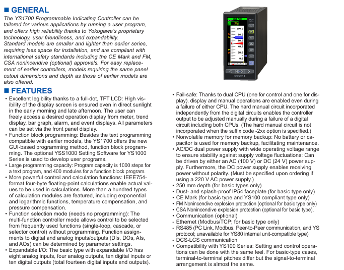
The YS1700 Programmable Indicating Controller can be tailored for various applications by running a user program,and offers high reliability thanks to Yokogawa’s proprietary technology, user friendliness, and expandability.

Standard models are smaller and lighter than earlier series,requiring less space for installation, and are compliant with international safety standards including the CE Mark and FM,CSA nonincendive (optional) approvals. For easy replacement of earlier controllers, models requiring the same panel cutout dimensions and depth as those of earlier models are also offered.

FEATURES

• Excellent legibility thanks to a full-dot, TFT LCD: High visibility of the display screen is ensured even in direct sunlight in the early morning and late afternoon. The user can freely access a desired operation display from meter, trend display, bar graph, alarm, and event displays. All parameters can be set via the front panel display.

• Function block programming: Besides the text programming compatible with earlier models, the YS1700 offers the new GUI-based programming method, function block programming. The optional YSS1000 Setting Software for YS1000 Series is used to develop user programs.

• Large programming capacity: Program capacity is 1000 steps for a text program, and 400 modules for a function block program.

• More powerful control and calculation functions: IEEE754 format four-byte floating-point calculations enable actual values to be used in calculations. More than a hundred types of calculation modules are featured, including exponential and logarithmic functions, temperature compensation, and pressure compensation.

• Function selection mode (needs no programming): The multi-function controller mode allows control to be selected from frequently used functions (single-loop, cascade, or selector control) without programming. Function assignments to digital and analog inputs/outputs (DIs, DOs, AIs,

and AOs) can be determined by parameter settings.

• Expandable I/O: The basic type with expandable I/O has eight analog inputs, four analog outputs, ten digital inputs or ten digital outputs (total fourteen digital inputs and outputs).

• Fail-safe: Thanks to dual CPU (one for control and one for dis play), display and manual operations are enabled even during a failure of either CPU. The hard manual circuit incorporated independently from the digital circuits enables the controller output to be adjusted manually during a failure of a digital circuit including both CPUs. (The hard manual circuit is not incorporated when the suffix code -2xx option is specified.)

• Nonvolatile memory for memory backup: No battery or capacitor is used for memory backup, facilitating maintenance.

• AC/DC dual power supply with wide operating voltage range to ensure stability against supply voltage fluctuations: Can be driven by either an AC (100 V) or DC (24 V) power supply.Furthermore, the DC power supply enables receiving power without polarity. (Must be specified upon ordering if using a 220 V AC power supply.)

• 250 mm depth (for basic types only)

• Dust- and splash-proof IP54 faceplate (for basic type only)

• CE Mark (for basic type and YS100 compliant type only)

• FM Nonincendive explosion protection (optional for basic type only)

• CSA Nonincendive explosion protection (optional for basic type) .

• Communication (optional)

– Ethernet (Modbus/TCP; for basic type only)

– RS485 (PC Link, Modbus, Peer-to-Peer communication, and YS protocol; unavailable for YS80 internal unit-compatible type)

– DCS-LCS communication

• Compatibility with YS100 Series: Setting and control operations can be done with the same feel. For basic-type cases,terminal-to-terminal pitches differ but the signal to terminal arrangement is almost the same.

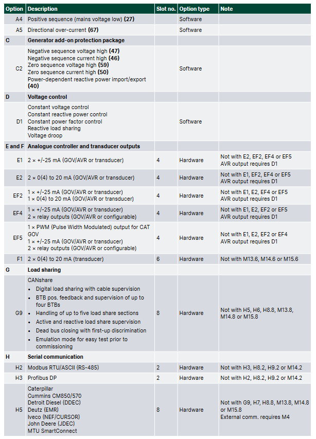
​Product Model Classification and I/O Configuration

YS1700 is divided into multiple models based on functionality and compatibility, with the core difference reflected in the number of I/O interfaces and compatibility with older devices. The specific parameters are shown in the table below:

Model Type Model Identification Analog Input (AI) Analog Output (AO) Digital Input/Output (DI/DO) Core Features

Basic YS1700-x0x 5 (1-5V DC) 2-channel 1-5V DC (1 channel can be changed to 4-20mA) 6 (DI/DO shared) Basic function, no expansion I/O, protection level IP54

Scalable I/O Basic YS1700-x1x 8 (including 3 extensions) 3 1-5V DC+1 4-20mA 14 (including 4 extensions) Supports I/O extensions, suitable for complex signal acquisition scenarios

YS100 compatible YS1700-x2x (/Ax) 5 (4 channels available) 2 channels 1-5V DC (1 channel can be changed to 4-20mA) 6 compatible YS100 series, signal terminal layout close to the old model

YS80 internal unit compatible YS1700-x3x 5 2-channel 1-5V DC (1 channel can be changed to 4-20mA) 6 compatible with old devices such as YS80, EBS, I, EK, HOMAC, etc

YS80 (YS100 terminal) compatible YS1700-x4x (/Ax) 5 (4 channels available) 2 channels 1-5V DC (1 channel can be changed to 4-20mA) 6 sizes compatible with YS80, terminal layout matching YS100

100 wire (YS100 terminal) compatible YS1700-x5x (/Ax) 5 (4 channels available) 2 channels 1-5V DC (1 channel can be changed to 4-20mA) 6 compatible with 100 wire pneumatic instrument replacement scenarios

Note: Some analog inputs can be changed to 4-20mA through parameter settings, and DI/DO terminals can be specified as input or output functions through parameters.

Core functions and technical features

1. Display and operation functions

High visibility display: using a 120 × 320 pixel full dot matrix TFT color LCD, supporting backlight brightness adjustment and off, even in direct sunlight in the morning and evening, it is still clearly visible; Provide multiple display modes such as dashboard, trend chart, bar chart, alarm, event, etc., which can be quickly switched through panel buttons.

Flexible data display: The tag number can display up to 12 characters, PV (process value) and SV (set value) can display up to 7 digits (including decimal point and symbol), and MV (operation value) can display up to 6 digits; The trend chart supports three types of variables (such as PV1/SV1/MV1), with a time span of 1.5 minutes to 45 hours, and can hide/display a single curve.

Convenient manual operation: The panel is equipped with SV/MV increase and decrease buttons, supporting FAST mode (MV adjustment speed 4 seconds/full range, normal mode 40 seconds/full range); When there is a malfunction, it automatically switches to FAIL display, and the hard manual wheel can adjust the output urgently.

2. Control mode and computing power

Dual control mode:

Programmable mode: Requires YSS1000 configuration software, supports basic control (BSC1/BSC2), cascade control (CSC), selector control (SSC) modules, and can freely combine control and calculation modules.

Function selection mode: No programming required, select commonly used functions (single loop, cascade, selector control) directly, and I/O functions are allocated through parameters.

Rich control types: Supports four control types: PID, PD, sample and hold PI, and batch PID. PID parameters (proportional range 0.1-999.9%, integration time 1-9999 seconds, differentiation time 0-9999 seconds) can be flexibly set, and additional functions such as self-tuning (STC), nonlinear PID, and output limitation can be added.

High precision calculation: using IEEE754 format 4-byte floating-point operation, supporting over 100 calculation modules such as exponential, logarithmic, temperature/pressure compensation, etc., to ensure data processing accuracy.

3. Programming and debugging skills

Dual programming mode:

Text programming: Program capacity of 1000 steps (main program+subroutines, subroutines can be reused), supporting logical operations, conditional judgments, jumps, and other instructions.

Function block programming: Based on GUI interface, with a program capacity of 400 modules, supporting online monitoring and testing operation, reducing programming barriers.

Online debugging: Through YSS1000 software, program testing, I/O signal simulation (up to 50 steps of simulation program), and functional block status monitoring can be achieved for easy troubleshooting and parameter optimization.

Data storage: Provides 30 P-parameter variables, 100 K-parameter constants, and 60 temporary data registers to meet the data storage needs of complex programs.

4. Communication function

Support multi protocol communication and adapt to different industrial control systems, with specific parameters as follows:

Key parameters of communication type interface/protocol applicable scenarios

RS-485 PC Link, Modbus RTU/ASCII, YS protocol, point-to-point communication connection PLC, PC or multiple YS1700 devices can be networked up to 32 devices, with a maximum communication distance of 1200 meters

Ethernet Modbus/TCP (basic type only) connection DCS/PLC, supports remote configuration and monitoring 10BASE-T/100BASE-TX, RJ45 interface, distance of 100 meters

DCS-LCS communication Yokogawa dedicated protocol connects up to 8 devices per LCS card in Yokogawa CENTUM CS 3000 and other DCS systems, with a communication distance of 100 meters

Programmer communication RS-232C (dedicated interface) downloads/uploads programs and parameters through YSS1000 software using a dedicated USB-RS232C cable, with a distance of approximately 2.7 meters

Host control mode: Supports DDC (direct control MV) and SPC (control SV) modes, and can automatically switch to manual (MAN) or automatic (AUT) backup mode when communication is interrupted.

Wiring cost optimization: Modbus multi station output supports 32 devices sharing one communication cable, reducing wiring workload.

5. Alarm and self diagnosis

Alarm function: Supports PV high and low limit/high and high limit/low and low limit alarms, deviation alarms, and rate alarms. The alarm threshold (-6.3-106.3%) and hysteresis (0.1-20.0%) can be set; When an alarm is triggered, the ALM yellow light will light up, the tag number will be displayed in reverse, and the event message can be stored and traced back on the ALARM interface (up to 5 messages).

Self diagnosis: It can detect hardware faults such as CPU failure, A/D/D/A conversion errors, memory errors, etc. When there is a fault, the FAIL red light will light up, the analog output will maintain the current value, the DO signal will be locked, and the hard manual function will be enabled.

Hardware specifications and environmental adaptability

1. Input and output electrical parameters

Signal type specification parameter accuracy requirements

Analog input (1-5V) input resistance 1M Ω, range 0-5.5V, supports direct input (mV, thermocouple, RTD, etc.) ± 0.1% range (basic type), ± 0.2% range (extended I/O)

Analog output (4-20mA) load resistance 0-750 Ω, output range 0.8-21.0mA ± 0.2% range

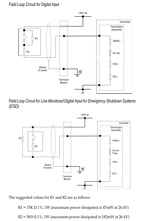
Digital input with no voltage contacts (below 200 Ω/above 100k Ω), voltage contacts (low -0.5-1V/high 4.5-30V), minimum pulse width of 70-220ms (according to control cycle)

Digital output transistor contact, open circuit output in case of 30V DC/200mA (resistive load) fault

Transmitter power supply 25-25.5V DC, load below 60mA (including 30mA below direct input) short circuit protection 80 ± 10mA

2. Environmental and mechanical characteristics

Working conditions: temperature 0-50 ℃, humidity 5-90% (non condensing), altitude below 2000 meters, atmospheric pressure 86-106kPa; Anti vibration (5-14Hz amplitude 0.625mm, 14-150Hz acceleration 4.9m/s ²), anti impact (49m/s ², within 11ms).

Protection and material: Basic panel protection IP54, shell 316 stainless steel; Insulation resistance 100M Ω (500V DC), withstand voltage 1000-3000V AC (depending on model), in compliance with IEC/EN 61010 safety standards.

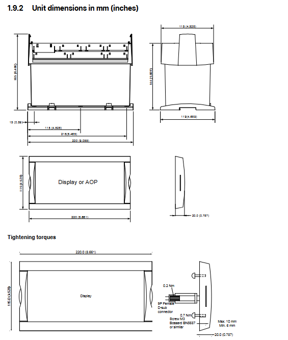
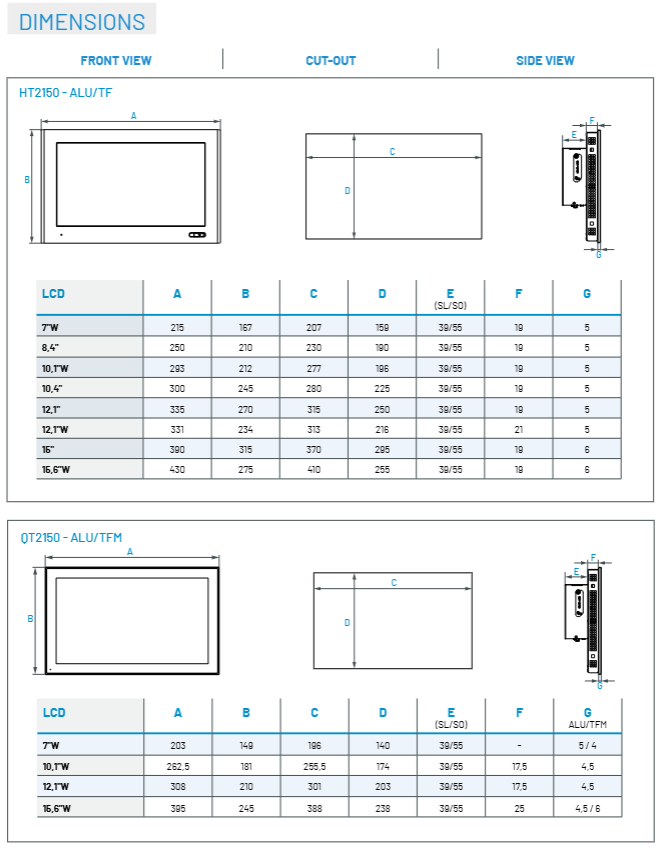
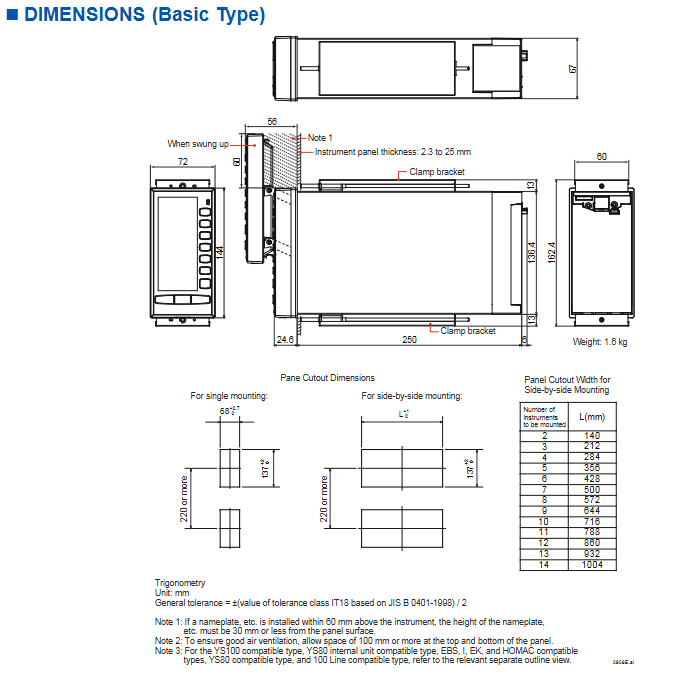
Size and Installation: The basic size is 144 × 72 × 250mm (H × W × D), with a panel opening of 137 × 68mm. It supports parallel installation, and the opening width needs to be adjusted according to the quantity when installing multiple devices (such as 2 units of 140mm and 3 units of 212mm).

Safety Compliance and Certification

General safety standards: comply with IEC/EN 61010-1/2-201/2-030, CAN/CSA-C22.2 No.61010 series standards, overvoltage category II, pollution level 2, measurement category O.

EMC standards: EN 61326 Class A, EN 55011 Class A Group 1, anti common mode noise 83dB, series mode noise 46dB (50/60Hz).

Hazardous Area Certification: Optional FM/CSA non flammable certification (Class I, Division 2, Groups A-D, Temperature Class T4), suitable for potentially explosive environments.

Environmental standards: Compliant with the EU RoHS directive (EN IEC 63000), with no harmful substances except for the A08 frequency input option.

Installation and Accessories

1. Installation requirements

Panel installation: The panel thickness is 2.3-25mm, with at least 60mm of space reserved at the top (to avoid obstruction during operation), and 100mm of ventilation space reserved above and below.

Expansion I/O installation: The expandable I/O type requires YS010 expansion terminals and YS011-03 expansion cables (3 meters), with a cable bending radius of ≥ 60mm.

Wiring specifications: The signal terminal and power terminal are both M4 screws. Shielded twisted pair cables are required for analog signals, and grounding must comply with Yokogawa grounding specifications.

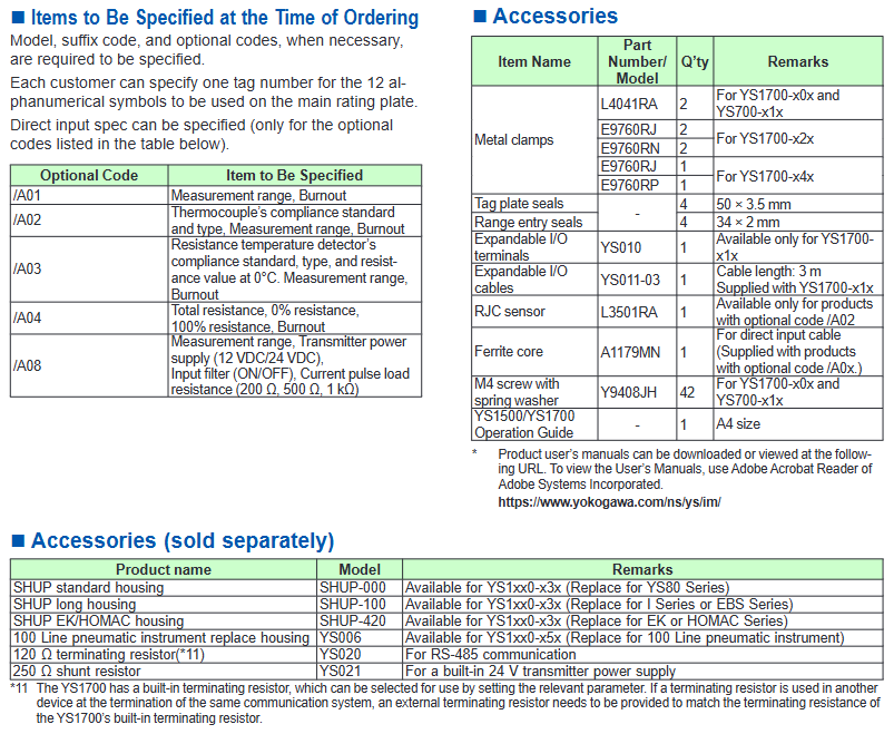
2. Standard and optional accessories

Accessory type, model, purpose, and remarks

Install brackets L4041RA, E9760RJ, and other fixed controllers onto the panel to adapt to different compatible controllers of different models

Expansion I/O accessories YS010 (terminal), YS011-03 (cable) are only applicable for expandable I/O type signal expansion YS1700-x1x

Temperature compensation accessory L3501RA (RJC sensor) thermocouple input reference compensation only/A02 option applicable

YS020 (120 Ω terminal resistor) and YS021 (250 Ω shunt resistor) resistor accessories are suitable for RS-485 communication matching and signal conversion. The terminal resistors can be enabled or not by parameter selection

Replace the shell SHUP-000/SHUP-100/SHUP-420, YS006 to adapt to the installation of old equipment, such as YS80 and 100 line instruments, and select the corresponding shell according to the compatible model

Honeywell Searchline Excel Infrared Open Circuit Gas Detector

Product positioning and market position

Core positioning: A globally leading infrared open circuit combustible gas detector with over 25000 units installed as of document release. It is widely used in various harsh industrial environments, deployed from the Arctic Circle to the Middle East desert, and is the preferred product for many customers.

Industry benchmark: In 1987, Honeywell first launched the first generation Searchline open circuit infrared combustible gas detector. After upgrading to Searchline Excel in 1998, it became the industry standard in the field of open circuit gas detection with performance that meets and exceeds customer needs. It is often paired with Searchpoint Optima Plus point detectors as the main combustible gas detection solution.

Core application scenarios

Suitable for industrial scenarios with high requirements for combustible gas detection, including:

Offshore platforms and vessels (such as floating production storage and offloading units FPSO)

Downstream chemical processing plants

Natural gas transportation and pipeline system

Large storage areas and factories

Perimeter detection scenario

Core features and advantages of the product

1. Environmental adaptability and reliability

Climate compensation: Using patented dual bandpass filters, it can fully compensate for various weather disturbances such as fog, rain, and mist, ensuring accurate detection under different climate conditions; Simultaneously possessing 100% resistance to light interference, avoiding the influence of sunlight on the detection results.

Endurance to harsh environments: Radial symmetrical and bonded window heating design ensures stable performance in low-temperature environments; High vibration resistance (2-60Hz, maximum peak to peak amplitude 1mm), suitable for industrial equipment vibration scenarios; The shell is made of 316 stainless steel material, with a protection level of IP66 and IP67, and is dustproof and waterproof.

Partial occlusion compatibility: The coaxial optical design is unique to the industry and can work normally when detecting partial occlusion in the path without the risk of false alarms; Similar products with non coaxial designs are prone to false alarms due to differential attenuation.

2. Performance and efficiency testing

High sensitivity and fast response: The detection range is 0-5 LEL · m (lower explosive limit · m), with a recommended low alarm threshold of 1.0 LEL · m and a high alarm threshold of 3.0 LEL · m. The response speed is fast, with T90 (time to reach 90% of the detection value) less than 3 seconds (under normal operating conditions).

Wide coverage and precise positioning: Supports three path lengths – short (5-40m), medium (40-120m), and long (120-200m). A single device can cover a wider area, reducing the deployment requirements of multi-point detectors; Can indicate the size of the danger zone and help staff quickly determine the risk range.

3. Installation and maintenance convenience

Easy calibration and alignment: equipped with a “locked” alignment tool and high-power, high magnification telescope, the alignment operation is simple and accurate, without the need for additional “software alignment” steps; The True Alignment system can achieve high-precision alignment without the need for subsequent software adjustments.

Low power consumption and convenient monitoring: Low power consumption under all operating conditions (maximum 3.5-5.0W for short-range transmitters, maximum 10-13W for medium and long-range transmitters, and maximum 8W for receivers); Optional Modbus RS485 multi station output, supporting 32 detectors sharing one communication cable, significantly reducing installation and wiring costs; By using XNX universal transmitter or SHC-1 handheld interrogator, local/remote configuration, status monitoring, and fault diagnosis can be achieved, reducing on-site maintenance frequency.

4. Safety certification and compliance

Obtained FM (Factory Mutual) hazardous area certification and performance certification, making it the world’s first open circuit gas detector to pass FM performance certification; It also complies with multiple international safety standards such as ATEX, UL, CSA, and is suitable for Class I hazardous areas (such as Class 1 Div 1/Zone 1).

Additional customized testing through FM: Honeywell engineers collaborate with FM to develop specialized simulation tests for scenarios not covered by FM standards such as “partial occlusion” and “fog/mist” to further validate product performance.

Advantages of open circuit gas detection technology (compared to point type detectors)

As a supplementary solution to point detectors, open circuit detectors have the following irreplaceable advantages:

The reliability of the detection has been verified through practical applications, reducing the risk of missed detections (for example, point detectors may miss pipeline leaks, while open circuit detectors can accurately capture them)

Covering a wider area makes it easier to detect leakage points at any location

The response speed is much higher than that of point detectors

Fault safety design: No unexposed fault modes, no problem of detector gas path blockage

The installation position requirements for detectors are lower, and there is no need to strictly align with potential leakage points

Easy installation and debugging, can replace multiple point detectors, and reduce overall deployment costs

Technical specifications and parameters

Category specific parameters

Detect gases such as methane, ethane, propane, butane, pentane, ethylene, propylene, and butadiene

Path length: Short distance: 5-40m; Medium distance: 40-120m; Long distance: 120-200m

Output signal 4-20mA (maximum loop resistance 600 Ω, supports source/drain output); RS485; 21mA over range, 2-3mA fault signal (user programmable)

Digital output needs to be paired with DX100 (M) or XNX universal transmitter with Modbus option, supporting Modbus RS485 multi station output

Environmental parameters: Operating humidity: 0-99% RH (non condensing); Work pressure: 91.5-105.5kPa (without pressure compensation)

Power supply and power consumption: 18-32VDC; Power consumption: Short range Tx 3.5-5.0W, medium to long range Tx 10-13W, Rx 8W (all maximum values)

Physical specifications and weight (including installation bracket): Short distance Tx 3.5kg, medium to long distance Tx 7kg, Rx 3.5kg; Alignment tolerance ± 0.5 °

Certification and Standard Performance Certification: FM; Safety Certification: ATEX, UL, CSA, GOST; EMC standard: EN50270

Preheating time ready:<5 minutes; Completely stable:<1 hour

Installation configuration and accessories

1. Installation options

Support multiple installation combinations for hazardous and safe areas, adapting to different control systems. Common solutions include:

Searchline Excel+DX100 (M) (UL/CSA/FM certified)+Controller/DCS/PLC

Searchline Excel+junction box (such as OTB122)+controller

Searchline Excel+XNX universal transmitter+controller/DCS/PLC (supports redundant 4-20mA signal, HART protocol)

Multi station Modbus output: Connect 32 detectors with a single cable to reduce wiring costs and support bidirectional digital communication (configuration, alarm, fault diagnosis)

2. Core accessories and functions

XNX universal transmitter: provides local display and supports HART ®、 Modbus、 Foundation Fieldbus ™) Waiting for interfaces to enhance compatibility between devices and control systems

SHC-1 handheld interrogator: equipped with a protection module, it can perform local invasive configuration and diagnosis of the detector in allowed scenarios

Telescope installation mechanism: a unique three-point installation benchmark ensures alignment accuracy; The perspective can be adjusted to the most convenient position without the need for subsequent software adjustments

Rockwell Automation ICS AADvance Controller 

Basic Information and Usage Standards

1. Scope of application and core objectives

Applicable products: AADvance controller series (T9100/T9110 processor modules, T9401/2 digital input modules, etc.) and supporting software (AADvance Workbench 1.4/2.1, AADvance Robust SIS Workstation 2.00), supporting system version 2.011.

Core objective: Define SIF safety application standards (mandatory) and recommendations to ensure that the system meets and maintains the required Safety Integrity Level (SIL), with a maximum support for SIL 3.

2. Key usage requirements

Personnel qualifications: Installation, configuration, operation and maintenance operations must be carried out by professionally trained personnel who are familiar with relevant regulations (such as IEC 61508, NFPA series standards).

Responsibility statement: If the device is used in a manner that does not comply with the manufacturer’s regulations, the protective function of the device may become ineffective; Rockwell is not responsible for indirect/consequential damages, and the examples in the manual are for illustration only and do not represent actual application guarantees.

System core features and authentication

1. Core functions and security design

Application scenarios: Suitable for safety critical scenarios such as emergency shutdown (ESD), fire and gas detection, rotating machinery control, burner management, etc., while supporting non safety but business critical control requirements.

Security Capability:

Both fail safe and fault tolerant architectures are supported, and fault tolerance can be realized through two module (1oo2D) or three module (2oo3D) configurations.

Built in comprehensive diagnostic function, capable of detecting hardware/software faults. The faulty module needs to be replaced within the mean time to repair (MTTR) to avoid a decrease in SIL level.

Supports two configurations: “Power Loss Trip (DTT)” and “Power On Action (ETA)”, and the number of modules needs to be selected based on SIL level and demand rate (high/low) (see Table 1).

2. Module configuration and SIL compliance requirements

Minimum module configuration for different application scenarios (simplified version of Table 1):

Application type, number of input modules, number of processor modules, number of output modules

SIL 2/3, Low/high demand, DTT 1 2 1

SIL 2, High demand, ETA 2 2 2

SIL 3, High demand, ETA 2 2 2

Note: The single channel digital output module includes a series switch. The DTT scenario supports SIL 3, while the ETA scenario only supports SIL 2; There are no three module output configuration options.

3. International certification and compliance standards

Functional safety certification: Compliant with IEC 61508 SIL 3, certified by an independent certification body.

Hazardous environment certification:

North America: Class I, Division 2, Groups A-D (UL 61010-2-201, CSA C22.2 standard).

Europe/UK: ATEX (DEMKO 11 ATEX 1129711X, Ex ec IIC T4 Gc), UKCA (UL24UKEX2993).

International: IECEx (certificate number IECEx UL 12.0032X).

Other compliance: Complies with industry standards such as EN 50156 (furnace control), EN 54 (fire alarm), NFPA 85/86/87 (boilers/ovens/fluid heaters), etc.

Safety lifecycle and management system

1. Safety lifecycle stages

The full lifecycle defined by IEC 61508 must be followed, with core stages including:

Scope definition: Clearly define system boundaries, interfaces (with processes/third-party equipment), and environmental requirements (such as temperature and power).

Hazard and Risk Analysis: Identify hazardous events, trigger sequences, and risk levels as inputs for safety requirements.

System Design and Engineering: Divide system architecture, define security requirement levels for each component, and refine hardware/software design.

Integration and Verification: The application is integrated with the controller to test and verify whether SIF meets SIL requirements (such as response time and fault handling).

Operation and Maintenance: Develop an operation/maintenance plan to ensure the SIL level is maintained during operation; Changes must be strictly controlled, and suspensions must follow safety procedures.

2. Requirements for Safety Management System

Policy and Planning: Functional safety policies need to be developed to clarify measures, responsibilities, and record management (including change control) for each stage of the lifecycle.

Personnel capability: Personnel qualifications need to be evaluated, including engineering experience, functional safety knowledge, regulatory familiarity, etc. Higher qualification requirements are required for high-risk scenarios.

Functional Safety Assessment (FSA): Led by senior personnel independent of the project, it reviews whether the entire lifecycle work meets the requirements.

System Architecture Design (SIL 2/3)

1. SIL 2 architecture

Fault safety architecture: single input (1oo1D), dual processor (1oo1D degraded), single output (1oo1D), triggering a safe state in case of a fault.

Fault tolerant input architecture: dual/triple input (1oo2D/2oo3D), dual processors, single output. When a single input module fails, it will operate in a degraded state while still maintaining safety functions.

High demand architecture: dual input, dual processor, dual output, ensuring that faulty modules are replaced within MTTR to avoid SIF shutdown.

2. SIL 3 architecture

Fault safe I/O+fault-tolerant processor: single input/output, dual/triple processor (1oo2D/2oo3D), downgraded in case of processor failure, dual fault triggers safe state.

Fault tolerant I/O architecture: dual input/output, dual processors, both input/output modules support 1oo2D degradation, suitable for high safety requirements scenarios.

TMR architecture: three inputs, three processors (2oo3D), dual outputs, with the strongest fault tolerance. A single module failure does not affect system operation. When there are two failures, it will be downgraded, and when there are three failures, it will trigger a safe state.

3. Secure network communication

SNCP protocol: SIL 3 certified “Black Channel” protocol, supports Ethernet transmission of secure data, achieves data exchange between controllers through “variable binding”, and can be configured as single network (fail safe) or dual network (fault-tolerant).

Peer to Peer communication: Supports SIL 3 data transmission between AADdistance and Trusted controllers, based on master-slave mode, and recommends using redundant networks to ensure availability.

Installation and environmental requirements

1. Non hazardous environment

Environmental conditions: temperature -25 ° C~+60 ° C, pollution level ≤ 2 (IEC 60664-1, only non-conductive pollution, occasional condensation); The burner management application requires an enclosure protection level of IP40 (indoor)/IP54 (outdoor).

Installation requirements: The module should be installed vertically (ensuring natural heat dissipation), DIN rail or wall mounted, without the need for forced air cooling.

2. Hazardous environment

Special requirements:

The enclosure protection level is ≥ IP54 (IEC 60079-0/7) and must be marked with “Do not open when powered on”.

Grounding wire cross-sectional area ≥ 3.31mm ², wire temperature rating ≥ 85 ° C, only supports vertical installation.

The temperature range is the same as non hazardous environments, and the pollution level is ≤ 2.

Operations and Security Assurance

1. Key daily maintenance items

Fault handling: When the processor/input/output module fails, it needs to be replaced within MTTR; If not replaced in a timely manner, the relevant SIF needs to be shut down (unless there are compensatory measures in the SRS document).

Calibration and testing: Regularly calibrate sensors/actuators, test SIF response time (≤ 1/2 of process safety time PST), and archive test records.

Backup and Update: Regularly backup system configuration (AADvance Workbench/SIS Workstation project) and test backup effectiveness; Firmware updates require the use of the ControlFLASH tool.

2. System security measures

Network security: it is forbidden to connect to the unprotected Internet; Computers need to have firewalls, antivirus software, and password protection enabled; The software license USB key needs to be properly kept.

Port security: Some Ethernet ports (such as TCP 1132, UDP 2010) are open by default, and unused ports need to be closed through a firewall (refer to the configuration guide).

Program Security: The application requires password protection, and the controller needs to insert the “Program Enable Key” to modify the configuration; It is prohibited to force I/O points during operation, and it is recommended to use the program’s “override” logic for maintenance.

Supporting documents and resources

1. Key related documents

Document Name Usage Description

AADvance Controller System Build Manual (ICSTT-RM448) System Assembly, Startup, and Operation Verification

AADvance PFH and PFDavg Data (ICSTT-RM449) Fault Probability (PFH/PFDavg) Data and Calculation Example

AADvance Troubleshooting and Maintenance Manual (ICSTT-RM406) System Maintenance, Troubleshooting, and Repair

2. Support channels

Technical support: Get help through rok.auto/support, register an account to subscribe to product security notifications.

Document download: Download the latest manuals and firmware from Rockwell Literature Library (rok.auto/iterative) or Product Compatibility and Download Center (rok.auto/pcdc).

Key Terminology (Glossary Simplified)

SIL (Safety Integrity Level): Safety Integrity Level, levels 1-4, with SIL 3 being the highest level supported by the manual.

PST (Process Safety Time): The maximum time for triggering a hazardous event when a hazardous state exists and there is no protection. The controller defaults to PST=2500ms and needs to be adjusted based on sensor/actuator delay.

MTTR (Mean Time To Repair): The average time to repair, during which faulty modules need to be replaced to maintain SIL.

1oo2D/2oo3D: Fault tolerant configuration, 1oo2D (2 out of 1 with diagnosis), 2oo3D (3 out of 2 with diagnosis).

image.png

ABB Relion ®  615 series RED615 line differential protection

Product basic positioning and core features

RED615 is ABB Relion ®  The intelligent electronic device (IED) for line differential protection and control under the 615 series is designed specifically for public utilities and industrial power systems. Its core application is the protection and control of overhead lines and cable feeders, and it is suitable for ring and mesh power grids with or without distributed generation. Its core characteristics can be summarized as:

Integrated protection function: with “line differential protection” as the core main protection, while integrating backup protection such as overcurrent, ground fault, circuit breaker failure, etc., to meet the requirements of modular protection;

Standardized communication: Deeply compliant with the IEC 61850 standard, supporting GOOSE messages (transmission delay ≤ 3ms), IEC 60870-5-103, Modbus ®、 DNP3 and other protocols, adapted for interconnection of substation automation systems;

Flexible configuration capability: Provides 3 standard configuration solutions, supports customizing signal logic through PCM600 tool, and adapts to different grounding methods (isolated neutral, resistance grounding, compensation grounding, direct grounding) of the power grid;

Full lifecycle support: Equipped with a complete documentation system (engineering, installation, debugging, operation and maintenance manuals), supporting local (LHMI) and remote (WHMI) operations, simplifying engineering and maintenance processes.

Document and symbol specifications

(1) Document system and audience

Document positioning: This document is the “Application Manual”, focusing on functional application scenarios and parameter setting guidelines. It needs to be used in conjunction with other manuals (such as the “Engineering Manual” for tool operation and the “Installation Manual” for physical installation);

Target audience: Protection and control engineers with knowledge of power engineering and communication protocols, responsible for equipment planning, preliminary engineering, and on-site debugging;

Version history: The current version is version B (released in July 2009), corresponding to product version 2.0. Compared to version A (October 2008), it has added support for DNP3 protocol, standard configuration B/C, and WHMI disturbance record upload function.

(2) Security and document symbols

Symbol Type Meaning Application Scenarios

The electrical warning icon poses a risk of electric shock and involves chapters on power wiring and terminal operation

Warning icons may pose a chain risk of personal injury caused by equipment failure, such as power grid accidents due to protection failure

Please note that icons may cause device damage, software abnormalities, parameter configuration errors, improper wiring, and other scenarios

Information icon key operation prompt function activation conditions and default parameter description

Suggestions for optimizing icon engineering, such as CT selection techniques and communication networking solutions

(3) Functional coding specification

The functional identification adopts a combination of “IEC 61850 name+IEC symbol+IEC-ANSI number”, for example:

Line differential protection: LNPLDF1 (IEC 61850), 3dI>L (IEC symbol), 87L (ANSI number);

Directional grounding fault protection: DEFLPDEF1 (IEC 61850), I ₀>→ (1) (IEC symbol), 67N-1 (1) (ANSI number).

Product hardware and operating interface

(1) Hardware structure

The RED615 hardware consists of a “plug-in unit+chassis”, and the core plug-in modules and functions are as follows:

Plug in module slot ID core function key parameters

Auxiliary power supply/BO module X100 provides auxiliary power supply, output trip/signal contact power input: 48-250V DC/100-240V AC; Including 2 sets of PO contacts and 1 set of SO contacts

Binary I/O module X110 binary input/output with 8 BI and 4 SO contacts

Analog input/BI module X120 collects current/voltage signals, expands BI 3-channel phase current (1/5A), 1-channel zero sequence current (1/5A or 0.2/1A), and 1-channel zero sequence voltage (configuration B exclusive)

Optional BIO module X130 expansion I/O with 6 BI and 3 SO contacts

Communication module X000 protocol communication supports Ethernet (100BASE-TX), RS-485, and fiber optic (ST interface)

(2) Operation interface

Local HMI (LHMI)

Display unit: LCD supports two character sizes (small characters: 5 rows x 20 columns; large characters: 4 rows x 8 columns), divided into four display areas: “title, icon, content, and scrollbar”;

LED indicator lights: 3 fixed protection lights (Ready/Start/Trip)+11 programmable alarm lights (such as differential protection action, CT fault);

Key functions: navigation key (switching menu), control key (circuit breaker opening and closing), function key (alarm confirmation, reset, local/remote switching).

Web HMI(WHMI)

Access method: accessed through IE 7.0+browser, disabled by default, requires manual activation;

Core functions: parameter configuration, real-time measurement value viewing, disturbance record download, phasor diagram display, menu structure consistent with LHMI;

Access range: Local (connected to laptop via front-end RJ-45 port) or remote (via LAN/WAN).

(3) User Authorization

Four types of user permissions are preset, with authorization disabled by default (WHMI mandatory), and passwords can be changed by administrators:

Typical operations within the scope of username permissions

VIEWER read-only view of measurement values and alarm logs

OPEROTOR control and status switching, local/remote mode switching, alarm reset

ENGINEER configuration and testing modify parameters, clear disturbance records, enter testing mode

Administrator full permission to change password and restore factory settings

Core functions and standard configurations

(1) Three standard configuration schemes

RED615 provides three predefined configurations that cover different ground fault protection requirements, with the following core differences:

Configuration Type Core Protection Function Applicable Scenarios Key Modules

Configure A (line differential protection), including line differential protection (87L), three-phase overcurrent protection (50P/51P), negative sequence overcurrent protection (46), and circuit breaker failure protection (51BF), for cable feeders. In scenarios where ground fault protection is not required, there is no zero sequence voltage input and the CT synthesis of zero sequence current is relied upon

Configuration B (including directional grounding fault protection) Configuration A: All functions+directional grounding fault protection (67N), transient/intermittent grounding fault protection (67NIEF), automatic reclosing (79). For overhead lines/cable mixed lines, it is necessary to distinguish the fault direction of the power grid (such as multi power distribution network), including zero sequence voltage input (U ₀), and adapt to the compensation grounding system

Configuration C (including non directional grounding fault protection) Configuration A: All functions+non directional grounding fault protection (50N/51N), automatic reclosing (79), radiation type distribution network, no need to distinguish fault direction scenarios (such as single power supply feeders) rely on CT synthesized zero sequence current, no zero sequence voltage input

(2) Detailed explanation of key protection functions

Line differential protection (LNPLDF1, 87L)

Core function: As the main protection, it realizes unit protection of the line and quickly cuts off internal faults;

Features: Contains stable low order (can be locked by CT fault detection) and instantaneous high order (can dynamically adjust the action value through remote circuit breaker status);

Communication dependency: It is necessary to establish protective communication with the remote IED, which will automatically lock in case of communication failure to avoid misoperation.

Earth fault protection

Directional (configuration B): Based on the phase of zero sequence current (I ₀) and zero sequence voltage (U ₀), the fault direction is determined, suitable for multi terminal power grids, divided into low order (sensitive section) and high order (fast section);

Non directional (configuration C): Based solely on zero sequence current amplitude action, suitable for single ended power grids, divided into low order, high-order, and instantaneous order.

Automatic reclosing (DARREC1, 79, configuration B/C optional)

Starting condition: triggered by protection action signals (such as overcurrent, ground fault);

Locking logic: The circuit breaker spring is not storing energy, the gas pressure is low, and it is locked when manually opening;

Status indication: LED5 is lit during the reclosing process, and an alarm is triggered when it fails.

Circuit breaker related protection and monitoring

Circuit breaker failure protection (CCBRBRF1, 51BF/51NBF): When the circuit breaker is not opened after the protection action, a trip command is sent to the upstream circuit breaker;

Trip Circuit Monitoring (TCSSCBR1/2, TCM): Monitor 2 sets of trip coil circuits, and lock the monitoring function when the circuit breaker is opened;

Circuit breaker status monitoring (SSCBR1, CBCM): Based on current and contact status, the mechanical characteristics of the circuit breaker are determined, and an alarm is triggered when there is an abnormality.

Communication and Networking

(1) Protocol support

Protocol type, functional scope, physical interface

IEC 61850 monitoring, control, parameter configuration, disturbance record upload (COMTRADE format), GOOSE message (trip level delay ≤ 3ms) Ethernet (RJ-45100BASE-TX)

IEC 60870-5-103 Protection signal upload, telemetry and remote signaling RS-485 or Ethernet

Modbus RTU/ASCII third-party device interconnection (such as PLC, SCADA) RS-485 or RS-232

DNP3 telemetry, remote signaling, remote control, supporting TCP/IP or serial Ethernet or RS-485

(2) Precautions for Communication Networking

GOOSE application: supports the highest performance level (transmission delay ≤ 3ms), meets the tripping requirements of distribution substations, and can simultaneously send events to 5 clients;

Client limitation: A single IED can support up to 5 concurrent clients. After PCM600 occupies 1, the remaining 4 can be allocated to other protocol clients;

Time synchronization: Line differential protection requires remote station time reference synchronization, which is recommended to be implemented through IEC 61850 or SNTP.

DEIF PPU-3 Parallel and Protection Unit

Product basic positioning and core applications

PPU-3 is a compact microprocessor control unit launched by DEIF, which integrates the protection and control functions of synchronous/asynchronous generators in an “integrated” design. It has a built-in galvanized separated three-phase measurement circuit and is designed for ship application scenarios. It supports two core working modes (which can be combined):

Stand alone operation: independent power supply control for a single generator;

Parallel with other generators: Multiple generators are synchronized in parallel to achieve load distribution and coordinated control.

Its core value lies in simplifying the generator control chain, which can be connected to the PLC control system through digital/analog I/O or serial communication, and has flexible functional expansion capabilities.

Core functional modules

(1) Display and operation unit

Display configuration: The display unit (DU-2) is independently designed and can be directly installed on the host or at the front end of the distribution cabinet door (with a standard 3m display cable). A single PPU-3 can expand up to 2 additional display units (up to 200m away);

Display content: Real time display of all measured values, calculated values, alarm information, and event logs;

Extended operation panel: Optional AOP-1 (16 configurable LEDs+8 configurable buttons) or AOP-2 (16 configurable LEDs+8 configurable buttons+1 status relay), supporting CAN bus communication.

(2) Regulation Modes

According to the control object (governor/automatic voltage regulator), provide multiple types of switchable standard regulation modes to meet different operational requirements:

Specific functions of control object adjustment mode

Governor maintains a fixed frequency to maintain stable generator output frequency

Fixed power (base load) setting for fixed active power output

Frequency droop automatically adjusts the frequency as the load changes, adapting to parallel load distribution

Load sharing: Balanced allocation of active loads when multiple machines are connected in parallel

Automatic voltage regulator (AVR, optional option D1) with fixed voltage to maintain stable generator output voltage

Fixed reactive power setting for fixed reactive power output

Fixed power factor maintains power factor stability

Reactive load sharing: Balanced allocation of reactive load when multiple machines are connected in parallel

Voltage droop automatically adjusts voltage with changes in reactive load, suitable for parallel scenarios

(3) Self checking and configuration tools

Self test: Perform periodic self tests at startup, display fault information in plain text on the screen, and trigger alarms through relay outputs (status outputs);

M-Logic (Micro PLC): Free integration into PC tool software, supports custom input/output functions and logic conditions, and adapts to personalized application scenarios;

Configuration method:

Local: configured through the password protection menu of the display unit;

Remote: Connect to a PC via USB and use the free Windows version PC tool software (available from the DEIF download center), which supports parameter monitoring, configuration saving/downloading, and firmware updates.

(4) Engine control and protection (optional function)

After installing the engine control and protection module, the PPU-3 can achieve:

Engine start stop sequence control;

Engine protection function: Provides a complete backup of the engine shutdown channel in case of main processor failure, ensuring equipment safety.

(5) CANshare function (optional G9 option)

CANshare provides:

Digital load distribution and line fault (disconnection, short circuit) monitoring;

Support position feedback and monitoring of up to 4 bus circuit breakers (BTBs);

Manage up to 5 load distribution segments;

Monitoring of active/reactive load distribution;

Dead bus closing and first startup discrimination;

Simulation testing mode before debugging.

Standard protection functions (Protections)

PPU-3 is equipped with multiple protection functions that comply with IEEE Std. C37.2-1996 (R2001) standards, covering core fault scenarios of generators and busbars. Some functions support multiple threshold settings:

Protection Function ANSI Number Threshold Order Core Function

Generator reverse power (32) 2nd order to prevent the generator from absorbing grid power (such as when the turbine loses steam)

Generator over current (50/51) 6th order protection of the generator from overload current damage

Voltage dependent overcurrent (51V) 1st order combined with voltage state to determine overcurrent and avoid false triggering

Inverse time over current (51) The larger the first-order current, the shorter the action time, making it suitable for different overload scenarios

Generator over/under voltage (59)/(27) 2nd/3rd order protection for generator insulation and load from overvoltage/undervoltage impact

Generator over/under frequency (81) 3rd/3rd order to prevent frequency deviation caused by abnormal generator speed

Busbar over/undervoltage (59)/(27) 3rd/4th order protection for busbars and downstream loads from overvoltage/undervoltage damage

Busbar over/under frequency (81) 3rd/4th order to maintain bus frequency stability

Busbar voltage imbalance (60) 1st order prevention of equipment failure caused by three-phase voltage imbalance

Generator overload (32) 5th order to avoid long-term operation of the generator beyond rated load

Current/Voltage Imbalance (60) 1st order protection for generators and loads from damage caused by unbalanced current/voltage

Overexcitation/Loss of excitation (40/32 RV) 1st order protection generator excitation system to avoid magnetic field anomalies

Hardware and interface specifications

(1) Hardware architecture and slot allocation

The PPU-3 adopts a “slot based” hardware design, with fixed slots corresponding to different functional modules. Each slot only supports one hardware option, and the core slot functions are as follows:

Slot Number Function Category Standard Configuration/Optional Options Core Interface and Parameters

1. Power supply and basic I/O standard 8-36V DC power supply (11W); 1 status output relay; 5 relay outputs; 2 pulse outputs (kWh, kvarh); 5 digit inputs

Communication options include H2 (Modbus RTU/ASCII, RS-485), H3 (Profibus DP), etc., which are responsible for serial communication with external systems such as PLCs

3 load distribution standards with 13 numerical inputs; 4 relay outputs; 1 P (active) load distribution line; 1 Q (reactive power) load distribution line; 2 external set point inputs (GOV/AVR)

4 GOV/AVR/transmitter output standards (4 relay outputs); Optional E1 (2-channel+/-25mA), E2 (2-channel 0 (4) -20mA) and other output control signals can be sent to the speed regulator/AVR, or used as transmitter signal output

5 AC measurement standards, 3 generator voltage inputs; 3-channel generator current input; 3-channel bus/grid voltage input

6 Analog Output Expansion Optional F1 (2-channel 0 (4) -20mA transmitter output) to expand analog output channels

7 engine control and I/O expansion options include M4 (engine control, digital/analog I/O) and H7 (software level engine communication) to achieve engine start stop control, I/O expansion, and specific engine protocol docking

8. Advanced communication and load distribution options include G9 (CANshare), H5 (specific engine protocols such as Caterpillar, MTU), digital load distribution, and engine specific communication protocol docking

9 Ethernet communication options include N (Ethernet TCP/IP, supporting Modbus TCP/IP, EtherNet/IP, SMS/email alarms) to achieve remote monitoring and alarm notification over Ethernet

(2) Key technical parameters

Parameter category specific specifications

Working environment temperature: -25~70 ° C (-25~60 ° C with N option; UL/cUL certified environment maximum 55 ° C); Humidity: 97% RH (IEC 60068-2-30); Altitude: 0-4000m (downgraded for use from 2001 to 4000m)

Measurement range voltage: 100~690V AC (± 20%, UL/cUL certified maximum 600V AC); Current: 1/5A AC (from CT); Frequency: 30~70Hz

Auxiliary power terminal 1-2:12/24V DC nominal (8-36V DC operation, maximum 11W); Terminal 98-99:12/24V DC nominal (8-36V DC operation, maximum 5W); 2A slow melting fuse protection is required

Input/output digital input: optocoupler isolation, 8-36V DC conduction (impedance 4.7k Ω); Analog input: 0 (4) -20mA (impedance 50 Ω) RPM(MPU:2-70V AC,10-10000Hz); Relay output: 250V AC/30V DC (5A, UL/cUL certified 2A resistive load); Analog output: 0 (4) -20mA/± 25mA (isolated, maximum load 500 Ω)

Electrically isolated AC voltage from other I/O: 3250V AC (50Hz, 1min); AC current and other I/O: 2200V AC (50Hz, 1min); Analog output and other I/O: 550V AC (50Hz, 1min)

Protection level host: IP20; Display unit: IP40 (optional L gasket can be upgraded to IP54, required for RS certification applications)

Certified ship certification: certified by all mainstream classification societies; Safety certification: EN 61010-1, UL 508, CSA 22.2 No.14-05; EMC certification: EN 61000-6-2/4, IEC 60255-26

Optional Features and Accessories

(1) Core optional options (some key options)

Specific description of option code function category

A-series power grid protection package A1 (limited time undervoltage 27t, undervoltage+low reactive power 27Q, etc.), A5 (directional overcurrent 67)

C2 Generator Extended Protection Package Negative Sequence Voltage High 47, Negative Sequence Current High 46, Zero Sequence Voltage High 59, etc

D1 Voltage Control Fixed Voltage, Fixed Reactive Power, Fixed Power Factor, Reactive Load Distribution, Voltage Drop

G9 CANshare digital load distribution+line monitoring, multi BTB monitoring, dead bus closing

H2/H3 serial communication H2 (Modbus RTU/ASCII, RS-485), H3 (Profibus DP)

N Ethernet Modbus TCP/IP, EtherNet/IP, SMS/email alerts

Y1/Y11 display and control Y1 (engine and GB control), Y11 (display unit without local control button)

(2) Standard and optional accessories

Accessory type, specific product usage, model/remarks

Display Unit DU-2 (Standard): The host is equipped with Display 2912210050, and the display layout needs to be specified

DU-2 (extension) additional extension display 2912890030, supports CAN bus

AOP-1 expansion operation buttons and LED 2912890040 on the operation panel, with a maximum of one unit per display

AOP-2 expansion panel with status relay 2912890050, up to 5 units per PPU-3

Cable display cable (3m/6m/1m) connects the display unit to the host 1022040076 (3m), 1022040057 (6m), etc

USB cable (3m) PC configuration connection 1022040065

Cross Ethernet cable (3m) N option Ethernet connection 1022040055

IP54 display gasket (L) enhances the protection level of the display unit 1134510010, required for RS certification

Ordering and Disclaimer

(1) Order specifications

Required information: model (such as PPU-3 Marine), variant number (such as 01 with display/07 without display), product number (such as 2912210030-01);

Optional information: Please specify the selected functional options (such as M4, Y1, H2) and accessories (such as AOP-2, IP54 gasket);

Example: Product number 2912210030-01 (PPU-3 Marine 01 with display)+option M4 (engine control)+Y1 (engine and GB control)+H2 (Modbus RTU).

(2) Disclaimer

DEIF reserves the right to modify document content without prior notice;

The English version of the document is the latest authoritative version, and there may be delays in the translated version. In case of any conflicts, the English version shall prevail;

DEIF is not responsible for the accuracy of the translated version.

image.png

Foxboro PBCO-D8-009 Terminal Board (TB)

Product basic positioning and core role

PBCO-D8-009 is a Termination Board (TB) launched by G.M. International. Its core function is to directly connect D1000 series intrinsic safety isolation and protection modules, and interface with Foxboro FBM series I/O cards (FBM211, FBM207b, FBM241c, FBM242). It can achieve backplane interface connection without the need for conventional Field Termination Assembly, simplifying the signal transmission link between safe and dangerous areas in industrial control systems, and combining cost-effectiveness and design convenience.

Compatible device and module configuration

(1) Compatible FBM I/O card types and parameters

The terminal board provides dedicated interfaces for FBM cards of different signal types, and the functions and channel configurations of each card are as follows:

FBM I/O card model type channel configuration core purpose

FBM211 Analog Input (AI) board with 16 channels, 4-20mA signal reception for on-site analog signals (such as sensor data)

FBM207b digital input (DI) board 16 channels receive on-site digital input signals (such as switch status, proximity sensor signals)

FBM241c digital input/output (DI/DO) board with 8 channels DI+8 channels DO simultaneously receives digital input signals and outputs control signals (such as driving solenoid valves)

FBM242 digital output (DO) board 16 channel output digital control signals (such as control actuators, indicator lights)

(2) Matching D1000 series modules

The terminal board needs to be equipped with D1000 series intrinsic safety modules to achieve signal isolation and protection. The module types corresponding to different I/O cards are fixed, as follows:

FBM I/O card model matches D1000 module type module function

FBM211 (analog input) D100D, D104D, D1052D, D1072D analog signal isolation, supports 4-20mA signal transmission, some modules (D101D/D104D) are compatible with HART protocol

FBM207b (digital input), FBM241c (DI part) D1030D, D1032D digital input signal isolation, suitable for voltage contactless signals and proximity sensor signals

FBM241c (DO section), FBM242 (digital output) D1049D digital output signal isolation, driving solenoid valves and other loads, supporting load diagnosis

(3) Channel capacity limitation

The terminal board only supports 2-channel modules, and a single TB can achieve any of the following channel configurations:

16 channel analog input (AI)

16 channel digital input (DI)

8-channel digital input+8-channel digital output (DI+DO)

16 channel digital output (DO)

Core Features and Product Highlights

Simplified wiring and compatibility:

The terminal board connector is pin compatible with standard system cables, without the need for dedicated cables or additional external wiring; Connect with Provox I/O cards through standard Provox cables to reduce wiring complexity and cost.

Intrinsic safety and isolation protection:

Relying on D1000 series associated devices to achieve intrinsic safety protection and signal isolation, the connection between hazardous and safe areas is only completed through module terminal blocks, and the terminal board does not require separate intrinsic safety certification, shortening the design cycle.

Redundant power supply and flexible expansion:

The 24Vdc power supply is connected through a dual plug terminal block, supporting redundant power supply and daisy chain connection (even if the terminal block is not plugged into the corresponding matching connector). The power supply is distributed to the isolation module through the terminal board bus to ensure power supply stability.

Convenient installation and maintenance:

Equipped with sturdy carbon steel painted plate bracket, supporting surface installation (4 M6 screw mounting slots);

Equipped with Shield Rail, 5 M5x10 holes for cable shielding layer connection, and 1 M4x10 screw for grounding;

Provide backup fuses (2A delay type), power failure monitoring function, and support label labeling at the top to reduce maintenance difficulty.

Status visualization:

Equipped with LED indicator lights – green indicates normal power supply, red indicates fault detection (such as abnormal power supply voltage), providing intuitive feedback on equipment operation status.

Technical specifications and parameters

(1) Power Supply and Protection

Parameter category specific specifications

Power input nominal 24Vdc, input range 20-30Vdc, with reverse polarity protection

The power selection has a built-in OR diode, which can automatically select a higher voltage power source

Protection fuse 2A delay type (onboard backup fuse)

Fault detection power supply voltage fault threshold: ≤ 18Vdc; The fault signal is output through the contact of the NE SPDT relay without voltage (the relay loses power in case of fault)

Relay parameter contact material: AgCdO; Contact rating: 2A 250Vac (500VA), 2A 250Vdc (80W, resistive load); Mechanical lifespan 3 × 10 ⁶ times, electrical lifespan 1 × 10 ⁵ times

(2) Connection interface

Interface type specification and purpose

Terminal block polarized plug-in disconnect screw terminal block, supporting up to 2.5mm ² wire

FBM I/O card interface SUB D 37 pin male connector (to be used with female connector)

Shielding and grounding shielding rails (5 M5x10 holes), grounding screws (M4x10)

(3) Environmental and Physical Characteristics

Parameter category specific specifications

Working environment temperature: -20~+60 ° C; relative humidity: ≤ 90% (below 35 ° C, no condensation)

Storage environment temperature: -45~+80 ° C

Installation method: Surface installation

Dimensions (width x depth x height) 224mm x 190mm x 122mm

Weight approximately 940g (excluding modules)

Applicable Area: Safe Zone/Non Hazardous Zone

Wiring and Circuit Design

The document provides detailed loop diagrams and connection tables, clarifying the signal flow direction between the HAZARDOUS Area and the SAFE Area. The core wiring logic is as follows:

(1) FBM211 (16AI) and FBM207b (16DI)

FBM211: Equipped with analog modules such as D1014D, hazardous area field equipment (such as 4-20mA transmitters) is connected through the module terminal block, and the signal is isolated and transmitted to the corresponding channel of FBM211. Some modules support HART multiplexer.

FBM207b: Equipped with digital modules such as D1032D, the voltage non-contact signal and proximity sensor signal in the hazardous area are isolated by the module and connected to the digital input channel of FBM207b.

(2) FBM241c (8DI+8DO) and FBM242 (16DO)

FBM241c: DI section (terminal board positions 1-4) is equipped with D1032D module to connect digital input signals; The DO section (terminal board positions 5-8) is equipped with D1049D module, which outputs signals to drive hazardous area solenoid valves and other loads, supporting load diagnosis.

FBM242: The full channel (terminal board positions 1-8) is equipped with D1049D module to output digital control signals to hazardous area loads (such as solenoid valves). The module is responsible for signal isolation and load status monitoring.

All wiring tables clearly indicate the corresponding relationship between “field equipment module terminal block terminal board connector pins FBM card channel redundant connector pins”, and the FBM card interface (CON4) is a SUB D 37 pin male connector, with the shielding layer uniformly connected to the shielding terminal block of pin 1.

Order Information

Product Model: PBCO-D8-009

Product Description: 8-bit terminal board, compatible with Foxboro FBM I/O cards (FBM211, FBM207b, FBM241c, FBM242), required to be used with D1000 series intrinsic safety modules.

ASEM HT2150/QT2150 Fanless Panel Control Computer (IPC)

Product positioning and core highlights

(1) Basic positioning

HT2150 and QT2150 are entry-level fanless panel industrial control computers (Panel IPC) launched by ASEM, based on Intel ®  Bay Trail ™  The system on chip (SoC) platform, which focuses on high cost performance, is suitable for industrial automation, human-computer interaction (HMI), edge computing and other scenarios, especially for industrial environments that require equipment volume, heat dissipation and stability.

(2) Core Highlights

Fanless design: adopting passive heat dissipation to avoid equipment shutdown caused by fan failure, adapting to a wide working temperature range of 0 ° C~50 ° C, and improving reliability in industrial scenarios.

Flexible display and touch configuration: covering multiple sizes and ratios of LED backlit TFT LCD screens, supporting resistive and capacitive touch to meet different operational needs.

High performance hardware foundation: equipped with Intel ®  Celeron ®  J1900 quad core processor with expandable memory up to 8GB, combined with rich storage interfaces, balancing computing and data storage capabilities.

Multi version and scalability: Provides “SL Short Depth Edition” (more compact in size) and “S0 Expansion Edition” (supporting the installation of additional interface boards) to adapt to different installation spaces and functional requirements.

Industrial grade protection and power supply: The front protection level reaches IP66, supports 24VDC isolated power input, and optional integrated UPS (requires external battery pack) to ensure stable operation of equipment in complex industrial environments.

Software and Remote Support: Pre installed UBIQUITY remote assistance software (remote access through end-to-end VPN), optional FactoryTalk ®  Optix ™  The software is used for HMI and edge computing applications and supports 32/64 bit operating systems.

Hardware specifications and configuration

(1) Core hardware parameters

Specific configuration of hardware category

Intel processor ®  Celeron ®  J1900 quad core processor, base frequency 2.0GHz, supports 64 bit operations, 2MB L2 cache (onboard soldering, non replaceable)

Graphics card integrated with Intel ®  HD Graphics, Core frequency 688MHz (Turbo mode 854MHz), supports LVDS 8-bit/color digital interface

1 DDR3 SODIMM slot for RAM, supporting 1GB/2GB/4GB/8GB memory expansion

Storage interface -1 SATA II standard CFast slot (rear external access, supports booting)

-1 onboard mSATA connector (supporting SATA II SSD for extended storage)

Network interface 2 Gigabit Ethernet ports (RJ45, Intel) ®  I210 chip), supporting “Jumbo Frame” and “Wake on Lan” functions

USB interface – rear: 1 USB 3.0 (Type-A), 1 USB 2.0 (Type-A)

-Front end (QT2150 only): 1 USB 2.0 (Type-A, with protection)

Power input 24VDC isolated power supply (input range 18~32VDC), optional UPS kit (requires external battery pack), supports ATX mode power supply

(2) Display and Touch Configuration

HT2150 and QT2150 provide differentiated options for display and touch, covering different sizes, proportions, and touch types, as shown in the table below:

Product series Screen size and resolution Screen ratio Touch type Front panel material

HT2150-4:3 ratio: 6.5 “(640×480), 8.4” (800×600), 10.4 “(800×600), 12.1” (800×600/1024×768), 15 “(1024×768)

-Wide Screen (W): 7 “(800×480), 10.1” (1280×800), 12.1 “(1280×800), 15.6” (1366×768) 4:3/Wide Screen 5-Wire Resistive (HT2150), Projection Capacitive Multi Touch (HT2150-TFM) Aluminum Alloy (ALU), Aluminum Alloy Flat (TF), Aluminum Alloy+Glass Flat (TFM)

QT2150- Wide Screen (W): 7 “(800×480), 10.1” (1280×800), 12.1 “(1280×800), 15.6” (1366×768)

-4:3 ratio: 15 “(1024×768, no TFM version) 4:3/widescreen 5-wire resistive (QT2150), projected capacitive multi touch (QT2150-TFM), aluminum alloy flat (TF), aluminum alloy+glass flat (TFM, narrow bezel design)

All screens are 16 million color LED backlit TFT LCD, with a front protection level of IP66-

(3) Extension interface (only supported in S0 version)

The S0 version reserves one expansion interface position (Position A), which can be equipped with various additional boards to meet personalized functional requirements. Optional expansion modules include:

Communication: 1 RS232/422/485 (DB15M)+1 USB 2.0; 1 isolated RS232/422/485 (DB15M)+1 USB 2.0; 2 RS232 (DB9M).

USB extension: 1/2 USB 2.0 (Type-A).

Network Expansion: 1 Gigabit Ethernet port (RJ45, Intel) ®  I210)+1 USB 2.0.

Fieldbus Expansion: 1 NETcore X board (supporting EtherCAT, EtherNet IP, PROFINET, PROFIBUS, CANopen protocols).

Wireless extension: 1 wireless/Bluetooth/modem adapter.

Product version differences

Both HT2150 and QT2150 are available in SL and S0 versions, with the core difference being their volume and expandability

Version Type Core Features Applicable Scenarios

The SL short depth version has smaller depth dimensions, compact structure, limited installation space without expansion interface, and does not require additional expansion functions in scenarios such as small control cabinets and compact production lines

S0 expansion version reserves one expansion interface position (Position A), which can be equipped with additional boards for complex industrial scenarios that require expansion of communication interfaces, fieldbus or wireless functions (such as large automation systems, multi device linkage scenarios)

Software and Compliance

(1) Supported operating systems

Certified compatible operating systems include:

Microsoft Windows 7 Pro/Ultimate (32/64 bit)

Microsoft Windows Embedded Standard 7E/7P (32/64 bit)

Microsoft Windows 8.1 Industry Pro (32/64 bit)

Microsoft Windows 10 IoT Enterprise 2016/2019 (64 bit)

(2) Pre installed and optional software

Pre installed software: UBIQUITY remote assistance software, supports remote device access and maintenance through end-to-end VPN connection, reducing on-site operation and maintenance costs.

Optional software: FactoryTalk ®  Optix ™  The software is used for HMI interface development and edge computing applications, and is suitable for real-time data processing and visualization requirements in industrial scenarios.

(3) Certification and Compliance

Safety certification: CE certification, cULus LISTED (compliant with IEC/EN/UL 61010 standards, applicable to the safety requirements of electrical equipment for measurement, control, and laboratory use).

Protection level: IP66 on the front (dustproof, waterproof splash), suitable for dust and humid environments in industrial sites.

Other key characteristics

UPS function (optional): Supports integrated UPS module, requires external battery pack, can provide temporary power supply in case of power failure, to prevent data loss or abnormal device shutdown.

Status indicator: Equipped with power indicator light, hard drive/SSD indicator light, overheat/low battery indicator light (when UPS function is enabled), UPS status indicator light, for real-time monitoring of equipment operation status.

Installation method: Supports panel mounting, suitable for standard installation scenarios of industrial control cabinets. The SL version’s short depth design further reduces installation space requirements.

ABB FOUNDATION ™  Fieldbus Link Device LD 810HSE Ex V1.0

Equipment positioning and core attributes

Product type: LD 810HSE Ex is a foundation launched by ABB ™  The Fieldbus (Foundation Fieldbus) connection device is registered as a 42c class device according to the HSE protocol specification. Its core function is to serve as a gateway between the FF-HSE (Foundation High Speed Ethernet) subnet and the FF-H1 link, enabling data exchange and management between different bus networks.

Physical and power characteristics: Protection level is IP20, supporting DIN rail installation; Powered by 24V DC, compatible with Ethernet transmission rates of 10 Mbit/s or 100 Mbit/s, and supports device redundancy configuration to enhance operational reliability in industrial scenarios.

Core functions

(1) Gateway core capability

LD 810HSE Ex serves as a gateway, responsible for key data exchange and device management between the FF-HSE subnet and the FF-H1 link. Its specific functions are as follows:

H1 Device Management: Automatically identify all devices connected to the H1 link and configure these H1 devices through the HSE network using System Management and Network Management functions; Simultaneously supporting the access of H1 device function blocks through HSE, enabling remote control and parameter reading of on-site devices.

Data forwarding and synchronization: supports process data forwarding between H1 links, as well as bidirectional process data forwarding between H1 and HSE subnets, ensuring real-time data interoperability at different network levels; As an SM Time Publisher, it distributes system time to H1 devices and provides a unified time reference for alarm timestamps.

Alarm and Event Distribution: Collect alarm and event information sent by H1 devices and distribute it to relevant devices (such as connectivity servers) in the HSE subnet, integrating it into the overall system’s alarm management system.

(2) HSE side functional module

Management Agent: Integrate System Management Agent and Network Management Agent to achieve standardized management of HSE subnets and associated H1 links.

Data exchange: Built in FMS server (Fieldbus Message Specification Server) provides object access services for H1 devices; Support the publishing/subscribing mechanism for H1 device process data to meet the real-time data transmission needs in industrial scenarios.

Time synchronization and maintenance: As an SNTP server (Simple Network Time Protocol Server) that complies with HSE standards, it achieves time synchronization within the HSE network; Provide maintenance functionality through a built-in web server, supporting firmware updates for linked devices and H1 power modules via HTTP or HTTPS protocols.

Function limitation: does not support Simple Network Management Protocol (SNMP); There is a clear resource limit on the HSE side, with specific parameters as shown in the table below:

HSE resource type upper limit value

64 HSE sessions have been configured

400 HSE virtual communication relationships (VCRs) have been configured

Automatic HSE session count 32

128 automatic HSE virtual communication relationships (VCRs)

H1-H1 data forwarding count 64

(3) H1 Link Side Function Module

Management and Data Interaction: Integrate System Management Manager and Network Management Manager to lead the management logic of H1 link; As an FMS client, it implements object access while supporting the publication and subscription of process data, as well as the reception and reporting of alarms and events.

Link Control: Serve as the Link Master in each H1 link, responsible for communication scheduling and resource allocation of the link; Support access to the Management Information Base (MIB) of H1 port from H1 network, but restrict write operations from H1 network to ensure network security.

Resource limit (single H1 channel): There are clear restrictions on the resource configuration of each H1 channel, with specific parameters as shown in the table below (note: the total number of VCRs of source/sink, client/server, and publisher/subscriber types in a single H1 channel must not exceed the “total connections” limit):

H1 channel resource type upper limit value

Total number of connections (VCRs) * 128

Number of overnight connections (alarm reception) 10

Number of client server connections: 39+1

Publisher+subscriber connections 100

LAS scheduling table quantity 2

Number of sub scheduling tables 4

The number of sequences in each sub schedule table is 64

The number of elements in each sequence is 4

LAS scheduling table field size (bytes) 2000

(4) H1 Live List

Record key information of all active H1 devices on the H1 chain, including node addresses, PD tags (Process Data Tags), and device IDs, to provide basic data support for device management and troubleshooting.

(5) Built in web server

Support access through a standard web browser (with JavaScript enabled) to query general information of linked devices (such as device status, configuration parameters, etc.), provided that the PC where the browser is located is connected to LD 810HSE Ex via Ethernet.

Installation and certification in hazardous environments

(1) Applicable environmental model

LD 810HSE Ex is suitable for scenarios with potential explosive environments and complies with the hazardous location classification requirements of the North American “Division model” and the European and IEC national “Zone model”.

(2) North American Certification (cULus)

Scope of application: If the equipment label has clear identification, it can be used in Class 1, Division 2, A/B/C/D hazardous or non hazardous locations.

Installation requirements: The equipment itself does not meet the requirements of impact resistance and IP54 (according to IEC 60529), and must be installed in a protective enclosure that complies with section 26.4 of IEC/EN 60079-0 (must meet the requirements of impact resistance and IP rating); The casing must be fully installed and undamaged. If the casing is damaged, the equipment is prohibited from operating.

(3) European and international certifications (ATEX, IECEx)

Certification criteria:

IEC 60079-0:2011 6th edition (including 2012 and 2013 revisions)/EN 60079-0:2012 (including A11:2013 revisions)

IEC 60079-11:2011 6th edition (including 2012 revision)/EN 60079-11:2012

IEC 60079-15:2010 4th edition/EN 60079-15:2010

Scope of application: If the equipment label or technical documentation clearly identifies it, it can be used in Zone 2 gas explosive environments with IIA, IIB, IIC explosive groups, T4 temperature levels after being installed in a tested protective enclosure.

Explosion proof label:

IECEx explosion-proof label: Ex nA [ic] IIC T4 Gc

ATEX explosion-proof label: II3G nA [ic] IIC T4 Gc

Note: [ic] Explosion proof method is only applicable to the FF-H1 fieldbus interface.

Compliance requirements: The equipment complies with relevant standards and regulations, and meets the requirements of Directive 2014/34/EU; When installed as part of a system in potentially explosive environments, it is necessary to strictly comply with the requirements of standards such as IEC/EN 60079-14.

At ABB Ability ™  Integration in IT system (800xA system)

(1) System Architecture Role

In a typical 800xA system architecture, FOUNDATION ™  The Fieldbus subsystem is connected to the control system (such as the AC 800M controller) through the HSE subnet, with LD 810HSE Ex serving as the gateway to establish a communication bridge between the field devices on the H1 link and the HSE subnet. The specific architecture is as follows:

Upper level system: including engineering workstation (Control Builder M workstation), operator maintenance workstation, Fieldbus Builder FF client/server network, and connectivity server with OPC server (FF Connectivity Server).

Control layer: The AC 800M controller is connected to the HSE subnet through the communication interface module CI860 (as the HSE host) to achieve control and data exchange of the Fieldbus subsystem.

Fieldbus subsystem: composed of multiple LD 810HSE Ex linked devices and H1 field devices, the linked devices communicate through HSE protocol and manage the H1 links under them, realizing the forwarding of process data and device management.

(2) Key integration capabilities

Data exchange: With the help of HSE data forwarding function, periodic communication between different H1 link on-site devices and HSE subnet devices can be configured to meet real-time control requirements.

Alarm integration: The alarms and events of H1 devices are transmitted to the FF connectivity server through linked devices, seamlessly integrated into the alarm management system of the 800xA system for unified monitoring and processing.

Redundant configuration: Supports LD 810HSE Ex redundant deployment, where the corresponding H1 ports of two physically linked devices in the redundant group are connected to the same H1 link, and redundant control information is exchanged through redundant link wiring to enhance system reliability.

Technical specifications and parameters

Technical parameter category specific parameters

Power supply input voltage: 18 V DC~32 V DC (mandatory requirement for SELV/PELV power supply); Typical input current: 200 mA; 4 FF-H1 channels output current: 10 mA each; maximum input current: 1 A (including startup surge current)

FF-H1 channel quantity: 4; Compliant with FF physical layer protocol specification Class 114; Fieldbus voltage range: 9 V DC~32 V DC (recommended value 24 V DC)

Ethernet complies with the IEEE 802.3 standard; Supports 100BASE-TX (100 Mbit/s) and 10BASE-T (10 Mbit/s)

Environmental temperature: Operating temperature: -40 ° C~+70 ° C; Storage temperature: -40 ° C~+85 ° C

Relative humidity 10%~95% (non condensing)

The highest altitude shall not exceed 2000 meters

Installation location for indoor use only; Avoid direct sunlight

The coating complies with the ANSI/ISA-S71.04 G3 standard and is a three proof coating (moisture-proof, salt spray resistant, and mold resistant)

The safety standards comply with IEC/EN/UL 61010-1 (Safety Requirements for Electrical Equipment for Measurement, Control and Laboratory Use – Part 1: General Requirements) and IEC/EN/UL 61010-2-201 (Part 2-201: Special Requirements for Control Equipment), both of which have passed the CB certification system

Protection level IP20

ABB Panel 800 Version 6 PP885 Hardware and Installation

Product positioning: Panel 800 Version 6 PP885 is an operation panel designed for human-computer interaction scenarios, suitable for industrial control fields. It can be connected to automation equipment such as PLCs, servo systems, and drives to achieve functions such as text display and control, dynamic indication, time channel management, alarm processing, and formula management.

Safety precautions

(1) General safety requirements

Preparation: Installation personnel, equipment owners, and operators must read and understand this installation manual; Carefully read the safety precautions and check if there is any transportation damage to the delivered products. If there is any damage, immediately notify the supplier; Suppliers are not responsible for modified, altered, or modified equipment and are only allowed to use parts and accessories that meet the supplier’s specifications.

Operation specifications: Before installing, using or repairing the operation panel, carefully read the installation and operation instructions; It is strictly prohibited for liquids, metal debris, or wiring debris to enter any opening of the operation panel to prevent fire or electric shock; Only qualified personnel are allowed to operate the control panel.

Storage and special case handling: The operation panel should be stored within the recommended temperature range. If the temperature is too low, it may cause the LCD display liquid to solidify, and if it is too high, it may cause isotopic phenomena; LCD display liquid contains highly irritating substances. If it comes into contact with the skin, immediately rinse with plenty of water. If it comes into contact with the eyes, open the eyes and rinse with plenty of water before seeking medical attention; The illustrations in the manual are only for illustration purposes. Due to the existence of multiple variables in the installation scenario, the supplier is not responsible for the actual use based on the illustrations; Suppliers do not guarantee that the operation panel is suitable for specific applications, nor are they responsible for product design, installation, or operation; It is recommended to perform at least one power on/off operation on the control panel before installing any components/cards or connecting external devices (such as serial devices).

(2) Disposal requirements under WEEE regulations

EU professional users: If you need to dispose of electrical and electronic equipment (EEE), you need to contact the distributor or supplier for further information.

Non EU country users: If you need to dispose of this product, you need to contact the local regulatory authority or distributor to understand the correct disposal method.

(3) UL and cUL installation requirements

Usage environment and power supply: The equipment is only suitable for Class 2 non hazardous locations; The combination of devices in the system must undergo inspection by the local regulatory authorities during installation; All devices must be powered by a Class 2 power supply, and disconnection is prohibited when powered on.

Expansion unit and battery: Only UL and cUL certified expansion units are allowed to be connected to ports labeled “EXPANSION”, and there are currently no such evaluated or approved units for use; Before replacing the expansion unit, it is necessary to ensure that the power is turned off or that the area is non hazardous; The product contains batteries and can only be replaced in known non hazardous areas. BR 2032 batteries must be used, as using other types of batteries may pose a risk of fire or explosion; Improper handling of batteries may cause explosions. Charging, dismantling, or putting them into fire is prohibited.

Installation and wiring: can only be used on flat surfaces of Class 4 indoor enclosures; Only copper wires with a minimum temperature rating of 75 ° C are allowed to be used; The wiring connection of the power cord connector must comply with the cable and torque specifications (the torque corresponding to the wire size is 3.5 pounds per inch); These devices are Class 2 power supply programmable controllers (industrial PCs) suitable for industrial control equipment, intended for (front) panel installation (Class 1 and Class 4X, indoor use only); The protection level of the shell should be at least IP20, but it needs to reach IP54 when installed in the equipment.

(4) Safety requirements during installation

Installation environment: The operation panel is designed for fixed installation on a flat surface, and the installation environment must meet the conditions of no high explosion risk, no strong magnetic field, no direct sunlight, and no drastic temperature changes.

Installation operation specifications: Install the operation panel according to the attached installation instructions and perform grounding treatment; Only qualified personnel are allowed to install the operation panel; Separate the layout of high-voltage cables, signal cables, and power supply cables; Before connecting the power socket, it is necessary to confirm that the power voltage and polarity are correct; Peripheral devices need to be suitable for the application scenario and installation location.

Special area installation: In Zone 2 environment, the equipment needs to be installed in a casing with a protection level of not less than IP54 and not more than IP65 (in accordance with IEC/EN 600079-0 standard), and the IP level of the equipment is limited by the IP level of the installed casing; In the 22 zone environment, the equipment needs to be installed in an enclosure with a protection level of not less than IP64 and not more than IP65 (in accordance with IEC/EN 600079-0 standard), and the IP level of the equipment is also limited by the IP level of the enclosure.

(5) Safety requirements during use

Keep the operation panel clean; Emergency stop and other safety functions shall not be controlled through the operation panel; Do not use excessive force or sharp objects when operating the touch screen.

(6) Service and Maintenance Security Requirements

Only qualified personnel are allowed to carry out repairs; Follow the agreed warranty terms; Before performing any cleaning or maintenance operations, the power connection of the equipment must be disconnected; Clean the display screen and surrounding front cover with a soft cloth and mild cleaning agent; Improper battery replacement may result in explosion. Only use batteries recommended by the supplier. During the warranty period, batteries must be replaced by authorized ABB service centers.

(7) Dismantling and scrapping safety requirements

The operation panel or its components must be recycled and disposed of in accordance with local regulations; Components such as lithium batteries, electrolytic capacitors, and displays in the equipment contain substances that may be harmful to health and the environment.

(8) Air appears in the touch screen

The layered structure of the touch screen contains air, and in rare cases, bubbles may appear, which only affects the appearance and does not affect any function of the operation panel. This phenomenon may occur under specific environmental conditions such as temperature, humidity, and air pressure.

image.png

Installation related

(1) Space requirements

Installation plate thickness: The maximum installation plate thickness is 8mm.

Size requirements: When installing the operation panel, the space requirements in all directions (unit: mm) are as follows: 100mm (partial area), 286mm (partial area), 50mm (both sides), 53mm (partial area), 410mm (overall relevant dimensions). Please refer to the outline drawing in the manual for accurate installation dimensions, which are not drawn to scale.

(2) Installation process

Preparation: Prepare Torx TX7 screwdriver; Unpack and inspect the delivered products. If any damage is found, notify the supplier; During installation, place the control panel on a stable surface to prevent it from falling and causing damage.

Cutting and fixing of openings: Cut suitable openings for the operation panel according to the opening size in the contour diagram (refer to the “Operation Panel Drawing” and “Technical Data” sections for detailed information); Use M4 Torx screws (specification M4 × 20.7, torque 0.4Nm) to secure the operation panel, ensuring that the built-in bracket is tightly attached to the panel.

Cable connection: Connect the cables in the specified order according to the diagram and the following steps:

Before starting the operation panel, it is necessary to reach the ambient temperature. If condensation occurs, ensure that the operation panel is dry before connecting to the power outlet.

Ensure that the operation panel and controller system have the same electrical grounding (reference voltage level), otherwise communication errors may occur.

Confirm that the power supply voltage and polarity are correct; Separate high-voltage cables from signal cables and power supply cables; Suggest using shielded communication cables.

Connect cable A (24V DC); Connect cable B using M5 screws and grounding wire (as short as possible, with dimensions in accordance with local electrical regulations); Connect cable C (Ethernet); Connect cable D (RS232/RS422/RS485), with a recommended cable cross-section of 1.5mm ².

Removal of protective film: Carefully remove the protective film on the operation panel display screen, taking care to avoid static electricity damaging the panel.

(3) Connection with controller

For information on the cables used to connect the control panel to the controller, please refer to the help files of the relevant driver programs.

(4) Other connections and peripheral devices

Cables, peripheral devices, and accessories should be suitable for the application scenario and its environment. For detailed information or suggestions, please consult the supplier.

Technical data

Project parameters

Cover layer Autoflex EBA 180L (see “Chemical Resistance” section for details)

Shell material powder coated aluminum

Communication interface (1) 9-pin D-sub interface, supports RS232 RTS/CTS, chassis mounting female head, with standard locking screw (4-40 UNC)

Communication interface (2) 9-pin D-sub interface, supports RS232 RTS/CTS, chassis mounting female head, with standard locking screw (4-40 UNC)

Store 2GB SSD (NAND Flash) and support formats with a maximum storage capacity of 2GB

1GB of memory (DDR2)

One multi-color indicator light (on-chip integrated)

Lithium battery, model BR 2032 (or CR 2032)

Power consumption 24W

Power input 3.15A slow melting,+24V DC (18-32V DC)

Power compliance CE: The power supply must comply with the requirements of IEC 60950 and IEC 61558-2-4 standards; UL and cUL: The power supply must meet the requirements of Class 2 power supply

Display TFT-LCD with LED backlight, resolution 1280 × 800 pixels, 262k colors

Display performance: brightness of 450cd/m ², horizontal viewing angle of 160 °, vertical viewing angle of 140 °

Backlight lifespan of 50000 hours

Display screen size 331.2 × 207.0mm

Working temperature range -10 ° C to+50 ° C

Storage temperature range -20 ° C to+70 ° C

Working humidity range 5% -85% (no condensation)

CE certification complies with EMC Directive 2004/108/EC+A1:2011

image.png

Chemical resistance

(1) Metal casing

Powder coating has almost no or no resistance to the following chemicals at room temperature: concentrated acetic acid, toluene, 30% nitric acid, and 97 octane unleaded gasoline.

(2) Touch screen and covering material

Autoflex EBA 180L: Not tolerant to high-pressure steam above 100 ° C, nor to various chemical substances (specific substance and contact time requirements: some substances may have adverse effects after 10 minutes of contact, please refer to the detailed list in the manual).

Touch screen surface: After exposure to solvents such as toluene, there is no visible change on the touch screen surface of the operation panel (refer to the manual for a detailed solvent list).

Touch screen protective film: It is recommended to use Autoflex EBA 180L protective film (model RX885/893, can be ordered from ABB), and its chemical resistance is detailed in the “Autoflex EBA 180L” section; Like all polyester based films, Autoflex EBA 180L is not suitable for long-term exposure to direct sunlight; The layered structure of the touch screen contains air, and in rare cases, bubbles may appear, which only affect the appearance and not the function, and may occur under specific environmental conditions.

Operation panel drawing

(1) Connector

The drawings indicate the positions of connectors and related interfaces (such as COM1/2, LAN, USB, C LAN, COM3/4, etc.), but COM4 is not supported on TxB SoftControl and TxB SoftMotion that include EtherCAT functionality. For detailed interface layout and pin definitions, please refer to the illustrations in the manual.

(2) Communication port

Port function and connection: The communication port supports protocols such as RS232, RS422, RS485, etc. Some port pins are defined as follows (example): RS232 TxD, RS422 Rx+, GND, RS422 Tx -, RS485 Tx -/Rx -, etc. (detailed pin allocation reference manual diagram); COM4 is not supported on specific models.

Special connection requirements: If two communication ports need to be used on the same physical port, Y-shaped distribution cable TK860V001 (part number 3BSE069476R1) must be used.

(3) PP885 contour

The contour diagram indicates the key dimensions of the operation panel (unit: mm), such as 286mm (partial length), maximum 8mm (related to installation plate thickness), 54mm (partial height), 268mm (partial length), 392mm (partial length), 410mm (overall length), etc. For detailed dimensions, please refer to the contour diagram in the manual.

image.png

Konica Minolta CM-3700A-U Plus spectrophotometer

Basic Equipment Information

(1) Equipment Introduction

CM-3700A-U Plus is a reflective high-precision fixed spectrophotometer developed specifically for measuring color and color difference in various industrial fields, meeting the high-precision requirements for color quality control in industrial production.

(2) Packaging and Protection

It is necessary to properly store all packaging materials (cardboard boxes, cushioning materials, plastic bags, etc.) used during equipment transportation. As the equipment is a precision measuring instrument, these materials are needed to reduce vibration and impact during subsequent maintenance and transportation; If the packaging materials are lost or damaged, please contact an authorized service agency.

When the equipment leaves the factory, the target mask is not installed at the target mask installation location, but a protective cover is installed to protect the sample measurement component (integrating ball opening). Before use, the protective cover must be removed, and during transportation, the protective cover must be installed. At the same time, the protective cover that comes with the equipment should be stored and used properly.

Precautions for use

(1) Operating environment

The equipment should be installed and used in an environment with an ambient temperature of 13-33 ° C, a relative humidity of ≤ 80% (at 33 ° C), and no condensation. Exceeding this range will affect the performance of the equipment.

The equipment and standard AC adapter (AC-A312F) are only designed for indoor use and are prohibited from outdoor use to prevent damage to the equipment due to factors such as rainwater.

The equipment is composed of precision electronic components, and disassembly or modification is prohibited as it may cause accidents such as malfunctions, electric shock, and fires; The equipment belongs to the second level pollution level product and is suitable for use in manufacturing environments, laboratories, warehouses, and other places that are not easily exposed to metal dust and condensed water; Simultaneously belonging to Class I overvoltage category products, they need to be connected to circuits that take measures to limit transient overvoltage to a lower level.

Prevent foreign objects from entering the equipment, and use extremely dangerous when the equipment comes into contact with water or metal; Avoid exposing the equipment to direct sunlight or near heating devices to prevent malfunctions caused by high internal temperatures; Avoid equipment experiencing drastic temperature changes and condensation; Prohibit the use of equipment in environments with high dust, smoke, chemical gases, or extreme humidity; The equipment should not be used at an altitude exceeding 2000 meters; Avoid using equipment near strong magnetic fields, such as speakers.

(2) System related

Prevent equipment from experiencing strong vibrations or impacts; Do not pull, forcefully bend, or apply excessive pressure to the connected cables to prevent cable breakage.

The sample measurement port and the interior of the integrating sphere of the equipment are high-precision components of the optical system, which need to be kept clean to avoid impact. When the equipment is not in use, a target mask should be installed and the sample measurement port should be covered.

The equipment and adapter belong to Class B EMC products, which may cause radio interference when used in a home environment. Users need to take appropriate measures to solve this problem; When the device encounters strong external static electricity, the display screen may go black or display abnormally, and communication with external devices may also be interrupted. At this time, the power needs to be turned off and restarted, and when restarting, wait a few seconds after turning off the power before restarting.

The device should be connected to a power source with as little noise as possible; The equipment complies with the “Electrical Equipment for Measurement, Control, and Laboratory Use – Electromagnetic Compatibility (EMC) Requirements – Part 1: General Requirements” (EU Harmonized Standard EN 61326-1:2021), and the consistency verification is conducted under the testing conditions of Konica Minolta in the industrial electromagnetic environment specified in the relevant Harmonized Standard. The performance degradation limit caused by continuous interference in the anti-interference test does not exceed 4 times the Konica Minolta repeatability specification (Δ E * ab).

When the device malfunctions or behaves abnormally, immediately turn off the power, disconnect the adapter plug, and refer to “Troubleshooting” (page 29); When the equipment malfunctions, it is prohibited to disassemble and repair it on your own, and authorized service agencies must be contacted.

(3) Measurement related

Ensure that there is no dust or dirt entering the opening of the device; After long-term use of the equipment, measurement values may deviate due to environmental factors. To ensure measurement accuracy, it is recommended to perform regular white calibration.

(4) White calibration board

The calibration data of the white calibration board should be measured at 23 ° C. To obtain the highest absolute measurement accuracy, calibration and measurement should be carried out at 23 ° C; Avoid scratching or staining the calibration plate with dirt; When installing the calibration board on the sample rack, it is prohibited to move it to prevent scratching; When not in use, cover with a lid to avoid exposure to external light.

(5) Target Mask

Do not touch the inner surface of the target mask (white coating surface) with your hands to prevent it from getting dirty or scratched; When not in use, it should be placed in the accessory storage space of the device to prevent exposure to external light.

(6) Power related

Turn off the power when the device is not in use; Use the designated AC adapter and connect it to a power outlet that meets the requirements; Use AC power supply with rated voltage (within ± 10% range); Ensure that the output plug of the adapter is not short circuited, otherwise it may cause fire or electric shock; Do not connect the adapter to overloaded circuits, and do not cover the adapter with cloth or other materials during use to prevent electric shock or fire; When removing the adapter from the device, first unplug the power cord from the socket, and then unplug the output plug.

Storage, cleaning, transportation, and maintenance

(1) Storage precautions

The equipment should be stored in an environment with a temperature of 0-40 ° C, a relative humidity of ≤ 80% (at 35 ° C), and no condensation. High temperature and humidity environments can affect the performance of the equipment. It is recommended to store it together with desiccants at or near room temperature.

Avoid storing equipment in direct sunlight or near heating devices to prevent malfunctions caused by high internal temperatures; When storing, prevent the device from condensing, and when transporting to the storage location, also be careful to avoid sudden temperature changes that may cause condensation.

Do not store equipment in environments with high dust, smoke, or chemical gases to prevent performance degradation or malfunction; When the device is not in use, a protective cover should be installed to prevent dust from entering the integrating sphere and affecting the measurement accuracy; Do not let the device have the target mask installed for a long time; Do not leave the device in the driver’s cabin or trunk of the vehicle to prevent malfunctions caused by temperature and humidity exceeding the allowed storage range.

The white calibration board may change color when exposed to light, and should be covered when not in use; The target mask may change color when exposed to light. When not in use, it should be stored in the accessory storage space of the device to avoid light exposure, scratches, and dust accumulation; When the equipment is not in use for a long time, it should be stored properly in the transport packaging; When operating the opening and closing parts of the attachment storage space, be careful not to pinch it.

(2) Cleaning precautions

When the surface of the equipment is dirty, wipe it with a soft dry cloth, and do not use organic solvents (such as naphtha, diluents) or other chemical reagents for cleaning.

When there is dust or dirt on the lens or receiver window, use a dust blower to remove it, and do not use organic solvents or other chemical reagents; When the interior of the white calibration board, zero calibration box, or target mask (except for the inner white coating surface) is dirty, use a soft, clean dry cloth to wipe it. For dirt that is difficult to remove, use a cloth dipped in ethanol to wipe it. After the cloth is dirty, it needs to be cleaned. Organic solvents or other chemical reagents are prohibited from being used.

When the surface of the white coating on the inside of the target mask or the inside of the integrating sphere is dirty, it is necessary to contact an authorized service agency; If the above methods cannot remove dirt or equipment scratches, contact an authorized service agency; When the equipment malfunctions, it is prohibited to disassemble and repair it on your own, and authorized service agencies must be contacted.

(3) Transportation precautions

Before transporting the equipment, it is necessary to remove the target mask and install a protective cover to protect the sample measuring components (integrating ball opening); The equipment weighs approximately 18kg and needs to be operated by two or more personnel when moving (including transporting) the equipment.

Packaging materials must be used when transporting equipment to reduce vibration and impact; When sending the equipment for repair, the equipment and all accessories must be packaged and sent out.

(4) Maintenance and Inspection

To ensure measurement accuracy, the equipment should be inspected once a year. For specific inspection matters, please contact the nearest authorized service agency of Konica Minolta.

(5) Disposal methods

Equipment, all accessories, and packaging materials must be properly disposed of or recycled in accordance with local laws and regulations to ensure compliance with environmental protection and relevant regulations.

Attachment information

(1) Standard attachments

Attachment Name, Model, Usage, and Precautions for Use

The white calibration board CM-A309 is used for reflectance measurement. When not in use, it needs to be covered to prevent dust accumulation, scratching, and exposure to external light

The zero calibration box CM-A155 is used for reflectance measurement. When using it for zero calibration, it should be installed correctly to avoid falling off due to external force, keep the interior clean, prevent scratching and fingerprint contamination, clean it according to regulations when it is dirty, and replace it if it is damaged and cannot be cleaned

When adjusting the illumination area (sample measurement port size) of the target mask CM-A310/A314 according to the sample, CM-A310 (SAV) has a measurement area of 1 × 3mm and an illumination area of 5 × 7mm. CM-A310 (SAV) must be used for zero calibration or white calibration of CM-A314 (USAV) with a measurement area of 1 × 3mm and an illumination area of 3 × 5mm. When installing, pay attention to the direction and avoid scratching the inner white coating surface. When not in use, place it in the accessory storage space

The AC adapter AC-A312F (ATS036T-A120) is connected to a power socket through an AC cable to supply power to the device. It has an input of 100-240V, 50-60Hz, maximum 1A, and an output of 12V 3A. The plug is the center positive pole, and this standard adapter must be used. When connecting, ensure that the plug is fully inserted to avoid short circuits and overloads, and do not wrap or cover it during use

USB cable IF-A48 (3m) is used to ensure correct direction and secure connection when connecting devices and computers. When plugging or unplugging, hold the plug and do not pull the cable to ensure sufficient cable length and avoid tension causing connection failure or cable breakage

(2) Optional attachments

Attachment Name Model/Relevant Information Purpose Acquisition Method/Instructions for Use

SpectraMagic NX2 Color Data Software – Used for controlling devices and managing data from a computer, which can be obtained through a USB flash drive or from the official website( https://www.konicaminolta.com/instruments/download/software/color/smnx2/index.html )To download and use, please refer to the software manual

Color palettes (white, black, and 12 other colors) CM-A247 to CM-A260 are used for measuring performance (instrument error and repeatability) of simple diagnostic equipment. When using them, follow the prescribed procedures to ensure that the measurement conditions meet the requirements

Green color chip CM-A101GN – used according to relevant operating specifications to assist in specific measurements or calibrations

When the dust cover CM-A307 device is stored in a dusty environment, it prevents foreign objects from entering the device. When covering the device, it ensures a snug fit and does not affect the normal heat dissipation of the device (used in non working conditions)

System diagram and component information

(1) System diagram

The CM-3700A-U Plus spectrophotometer can be connected to standard accessories (white calibration board CM-A309, zero calibration box CM-A155, target mask CM-A310/SAV, CM-A314/USAV, AC adapter AC-A312F, USB cable IF-A48) and optional accessories (SpectraMagic NX2 color data software, 14 color board CM-A247 to CM-A260, green color chip CM-A101GN, dust cover CM-A307). It can be connected to a computer through a USB cable to achieve computer control and data management of the equipment.

(2) Component Name and Function

Part Number, Part Name, Function

① Select a 5 × 7mm (SAV) or 3 × 5mm (USAV) illumination area for the target mask based on the sample to be measured, and install it on the device

② The sample rack is used to install reflectance measurement samples, white calibration plates, or zero calibration boxes

③ Environmental temperature and humidity meter measures the temperature and humidity of the environment

④ Fixture installation screw holes are used to install fixtures or other components to secure samples

⑤ When connecting the functional grounding terminal to the grounding wire, clamp the grounding wire between the screw and washer

⑥ USB connection terminal (Type B) connects devices and computers through the standard USB cable (IF-A48)

⑦ AC adapter input terminal connection provided

⑧ Attachment storage space stores attachments such as white calibration board, zero calibration box, target mask, etc

(3) Indicator light

Operation keys and power keys

Power button (POWER): used to turn on/off the device power, press once to turn on, long press to turn off; When the power is turned on, the LED light above the key lights up in blue; When the LED light flashes, it indicates that the AC adapter cannot be unplugged during the power on/off process.

Measurement button: Blue light indicates that measurement can be performed; Orange light indicates incomplete calibration; Not lit indicates measurement or power off.

STATUS PANEL

Measurement mode indicator lights (SCI, SCE, REF, KREF.): The LED lights on indicate the measurement mode set through computer software. In the “SCI+SCE” mode, both the SCI and SCE lights are on simultaneously; REF represents reflectance measurement.

Measurement area indicator light (1X3): indicates the specifications of the measurement area.

Communication status indicator light (CONNECT): It lights up when the device is connected to the computer (connected to PC software).

image.png

Search for products

Back to Top
Product has been added to your cart