Call us 24/7uaedcs@163.com
Welcome to the official website of CNIACS Automation Technology Co., Ltd!
Call us 24/7uaedcs@163.com

ABB AO2000-LS25 Laser Analysts User Manual

Product Overview

Core positioning: ABB AO2000-LS25 is a modular laser gas analyzer that operates in conjunction with the AO2000 integrated analysis system. It is based on tunable diode laser absorption spectroscopy (TDLAS) technology to measure gas concentration and only detects free molecules in the gas, insensitive to bound molecules.

Composition structure:

Unit Name Core Component Function Function

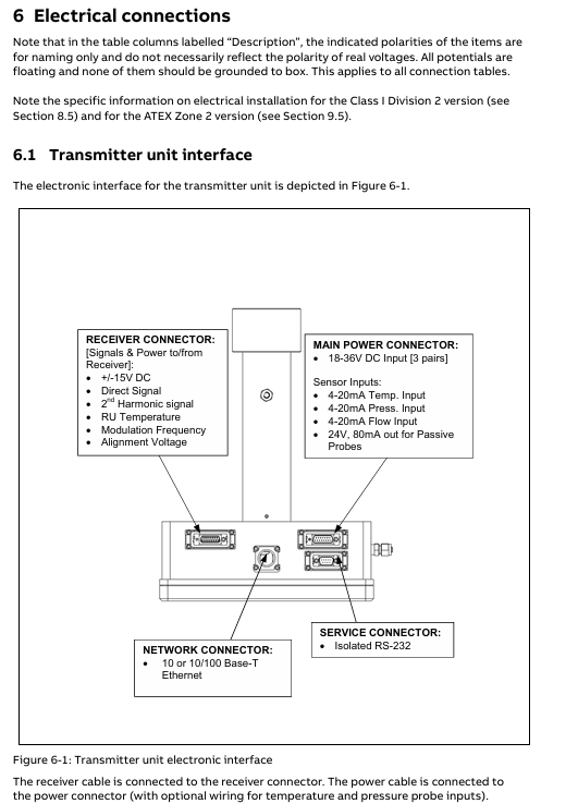
The transmitter unit temperature stable diode laser, collimating optical lens group, and main electronic equipment emit laser to complete laser wavelength scanning and basic light intensity measurement

The receiver unit focuses on the lens, photodetector, and electronic device at the receiving end to receive the laser absorbed by the gas, converts the optical signal into an electrical signal, and transmits it to the transmitter unit

The voltage conversion module of the power supply unit (100-240V AC to 24V DC) provides stable power supply for the transmitter and receiver, and supports direct connection to 24V DC

Protection and explosion prevention:

Conventional protection: The protection level of the transmitter and receiver units is IP66, and the standard optical window withstand voltage reaches 5 bar (absolute pressure).

Explosion proof version:

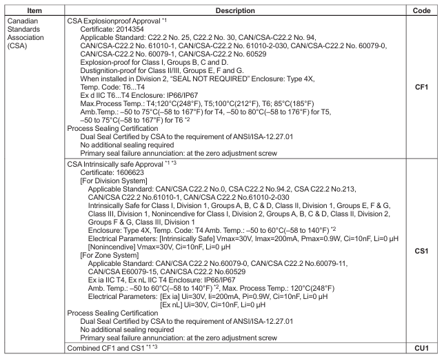
Class I Division 2 version: CSA certified, suitable for Groups A, B, C, D environments, temperature code T4, operating temperature -20~+55 ℃.

ATEX Zone 2 version: ATEX certified, certification number Presafe 16 ATEX 8621X, II 3 G Ex nA nC IIC T5 (special application T4), operating temperature -20~+55 ℃.

Key technical parameters

Description of specific indicators for parameter categories

The measurement objects CO, CO ₂, H ₂ O, NO, NO ₂, SO ₂, O ₂, CH ₄, etc. support multi-component selection and can measure up to 2 components simultaneously

Measurement accuracy ± 1% full scale based on TDLAS technology and harmonic analysis to achieve high-precision measurement

Response speed<1 second can quickly track dynamic changes in gas concentration

Operating environment temperature: -20~+50 ℃; Pressure: 1-10 bar ABS suitable for complex industrial working conditions

Laser classification O ₂ measurement is Class 1M, others are Class 1 in accordance with IEC 60825-1 standard, laser is near-infrared light (700-2400nm)

Power supply specification input: 110V-380V AC; Output: 24V DC power supply unit outputs 24V DC, transmitter unit inputs 18-36V DC

Physical characteristics: Weight of 3.6kg, warranty period of 1 year. Lightweight design with clear after-sales support

Installation and commissioning process

preliminary preparation

Tool requirements: 2 M16 open-end wrenches, 1 5mm hex wrench, 1 2.5mm flathead screwdriver, 1 PC (386 and above).

Measurement point requirements: At least 5 times the diameter of the straight pipe section is required before the measurement point, and at least 2 times the diameter of the straight pipe section is required after the measurement point; The transmitter and receiver units need to reserve operating space, and at least 1 meter of space should be reserved outside the flange of the receiver unit.

Flanges and Openings: Two pairs of perforations with a diameter of at least 50mm need to be opened on the pipeline/chimney, using DN50/PN10 standard flanges (inner diameter 50mm, outer diameter 165mm), with a flange angle tolerance of ± 1.5 °, and alignment tolerances that meet the requirements of DN50 flange δ min ≥ 40mm and DN80 flange δ min ≥ 55mm.

Cable requirements:

Special requirements for maximum length of cable type

The receiver cable is 150m long and cannot be replaced or modified at will (within ± 20m)

Ensure that all three sets of power cables are connected for a 100m power cable to ensure even current flow

Ethernet cable 100m outdoor use requires acid and UV resistance, supporting 10/100Base-T protocol

Service PC cable 10m standard length 3m, can be extended to about 10m

Installation steps

Install the alignment and blowing unit (DN50 flange) of the transmitter/receiver onto the process flange with 4 M16 × 60 bolts to ensure even compression of the O-ring.

Connect the blowing gas (instrument air or nitrogen), with a flange blowing flow rate of approximately 20-50 l/min, and a transmitter/receiver unit blowing flow rate of<0.5 l/min.

Install the window adapter ring (aligning with the positioning pin) and connect the transmitter/receiver unit to the adapter ring, paying attention to installing the O-ring (the transmitter side O-ring needs to be lubricated, while the adapter ring side O-ring is not lubricated).

Connect the cables of each unit: the receiver cable connects the transmitter and receiver, and the power cable connects the power unit and transmitter. If an external 4-20mA temperature and pressure sensor is required, it can be connected to the corresponding terminal of the power unit or transmitter.

Debugging and alignment

Startup process: After connecting the power, the instrument enters the startup mode (about 5 minutes), and the LCD displays the firmware version, self-test status, and laser temperature stability progress. If the “Laser line up error” is displayed after startup, alignment is required.

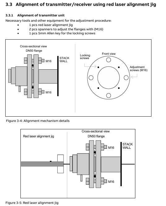
Alignment operation:

Remove the adapter ring of the transmitter/receiver and install the red laser calibration fixture.

Adjust the M16 adjustment screw on the transmitter side flange, align the laser beam with the center of the receiver side opening, and lock the locking screw.

Move the calibration fixture to the receiver side and repeat step 2 to align with the center of the opening on the transmitter side.

Connect the alignment interface of the transmitter/receiver with a voltmeter (voltage range 0V~-3V), fine tune the flange to maximize the voltage, and ensure that the transmission rate is between 90% -100% (low dust condition).

Software operation and parameter configuration

Software composition

Built in program: integrated into the CPU board, responsible for laser temperature control, signal acquisition, concentration calculation, and self checking, without the need for user operation.

Service program: Running on Windows system, connected to instruments via RS-232 or Ethernet, used for installation, configuration, calibration, troubleshooting, supporting user mode (simplified interface) and advanced mode (full functionality, password required).

Core function operation

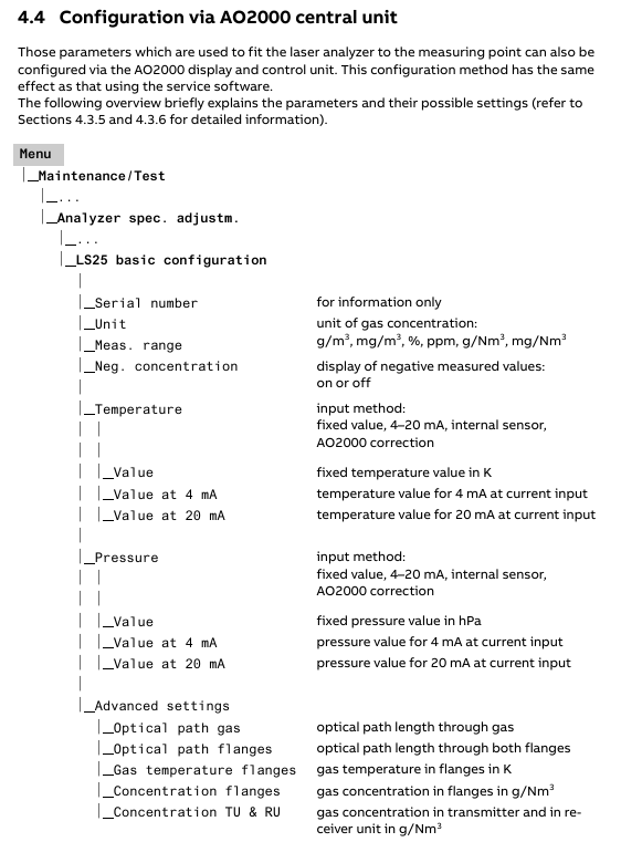
Parameter configuration (via the “Measurement configuration” menu):

Temperature and pressure settings: Fixed value, 4-20mA input, internal sensor or spectral measurement (temperature only) can be selected, pressure unit is bar abs (gauge pressure needs to be converted: P (abs)=1.013+P (gauge)), temperature unit is ℃ (Fahrenheit conversion: T (℃)=(T (℉) -32)/1.8).

Optical Path: Set the “Optical Path Length (Gas)” (usually the diameter of the pipeline) and “Optical Path Length (Flange)” (only required when there is a target gas inside the flange). The factory preset “Optical Path Length (inside the transmitter/receiver)” cannot be modified arbitrarily.

Concentration averaging: Set the average number of times (N), and the average time Tavg=N × Tprim (Tprim is the single measurement time, 1-4 seconds, depending on the gas type).

Calibration operation (via the “Calibrate instrument” menu):

Calibration mode applicable scenario operation requirements

PROPORTIONAL’s daily calibration and process gas calibration do not require temperature and pressure control, only adjusting calibration constants. It can calibrate a single gas separately and supports automatic calibration of associated gases

GLOBAL laser parameter drift, stable temperature and pressure environment (recommended 1.013bar, 23 ℃) after replacing core components, using standard gas and test cell, password authorization required

Recommended calibration gas concentrations: HF (50-500ppm, PTFE pool), HCl (15-200ppm), CO (0.5-5% vol or 50-500ppm), NO (500-5000ppm), etc.

Data log and fault viewing:

Log function: Set the sampling interval (minimum 2 seconds) through the “Log reads” menu, record parameters such as concentration, transmission rate, temperature and pressure, and support automatic generation of new files by date.

Fault viewing: The “View error log” menu displays fault/warning information (including activation/deactivation time), and can save fault logs and system logs for diagnosis. Common faults include “Low transmission” (cleaning window) and “Laser line up error” (realigning).

Maintenance and troubleshooting

routine maintenance

Regular inspection: Check the transmission rate daily, test the response with standard gas every 3 months (for at least 10 minutes), and calibrate every 3-12 months.

Window cleaning: When the transmission rate is too low, use non abrasive cleaning agents/solvents to clean the optical window. If the window has cracks, it needs to be replaced (pay attention to maintaining the original angle).

Blowing optimization: The flange blowing flow rate can be adjusted according to “blowing flow rate=1/10 process gas flow rate”, and the blowing effect can be verified by observing the concentration change after turning off the blowing for 30-60 seconds.

Common faults and solutions

Analysis of the causes of fault information and solutions

Low transmission (warning) Optical window contamination, transmitter/receiver alignment deviation. Clean the optical window and re align the laser

Laser line up error: The laser beam did not reach the detector and the optical path was obstructed. Check for any obstacles in the optical path, clean the window, and realign it

PLC T-read error: Temperature sensor current exceeds the range (<0.3mA or>23.7mA). Check the sensor wiring or switch to a fixed temperature setting

Low laser temp. (Error) Laser temperature adjustment malfunction, laser supercooling check transmitter heat dissipation. If it is not overheated, it may be a hardware failure. Contact after-sales service

EEPROM error: Internal memory failure. Upload backup settings file. If it occurs repeatedly, contact after-sales service

Key issue

Question 1: What are the core differences between the two calibration modes (PROPORTIONAL and GLOBAL) of ABB AO2000-LS25 laser analyzer, and which scenarios are they applicable to?

Answer: The core differences between the two calibration modes are reflected in the calibration objects, operational requirements, and applicable scenarios:

Calibration object: The PROPORTIONAL mode only adjusts the “calibration constant” and optimizes it based on the proportional relationship between the measured concentration and the standard concentration; Adjust the “calibration constant” and “linewidth parameter” simultaneously in GLOBAL mode, taking into account the reference measurement of absorbed linewidth.

Operation requirements: PROPORTIONAL mode does not require temperature and pressure environment control, does not require a password, and can be directly performed on the process site. It supports individual calibration of a single gas or automatic calibration of associated gases; GLOBAL mode requires stable temperature and pressure conditions (recommended 1.013bar, 23 ℃), uses standard gases and test cells, and requires advanced mode passwords (applied to ABB or distributors), making it more difficult to operate.

Applicable scenarios: PROPORTIONAL mode is suitable for daily calibration and adjustment when the deviation of process gas concentration is small (such as deviation<2-3%); GLOBAL mode is suitable for scenarios where laser spectral characteristics drift (such as after long-term use), core components such as laser modules/motherboards are replaced, or calibration effectiveness needs to be ensured over a wide temperature and pressure range.

Question 2: What are the key requirements for flange installation and purging system settings when installing ABB AO2000-LS25 laser analyzer, and what problems may arise if they are not met?

answer:

Key requirements for flange installation:

Flange specifications: DN50/PN10 standard flanges (inner diameter 50mm, outer diameter 165mm) are required. The diameter of the pipe/chimney opening should be at least 50mm, and the flange should be installed with perforations (in the diameter direction).

Tolerance requirements: The perpendicularity tolerance between the flange and the pipeline is ± 1.5 °, and the alignment tolerance must meet the requirements of DN50 flange δ min ≥ 40mm and DN80 flange δ min ≥ 55mm (where δ is the distance between parallel lines at the center of the flange).

Sealing requirements: During installation, it is necessary to ensure that the large O-ring between the flange and the alignment unit is evenly compressed, and the four M16 bolts need to be tightened evenly.

Consequences of failure to meet: Deviation in verticality or alignment can cause the laser to fail to align, resulting in a “Laser line up error”; Poor sealing of O-rings can lead to process gas leakage, contamination of optical windows, or pose safety risks.

Key requirements for setting up the blowing system:

Flange blowing: Use dry and clean instrument air (compliant with ISO 8573.1 Class 2-3, oil mist content ≤ 0.5mg/m ³) or nitrogen, with a flow rate of approximately 20-50 l/min and a recommended flow rate of 1/10 of the process gas flow rate.

Purging of transmitter/receiver unit: It should only be turned on under specific working conditions (such as high dust and corrosive environments), using nitrogen gas (to avoid damaging internal optical components with oil/water in the instrument air), with a flow rate of<0.5 l/min, to prevent excessive pressure inside the unit.

Failure to meet the consequences: Insufficient flange blowing flow will cause dust to deposit in the optical window, resulting in a decrease in transmission rate (warning of “Low transmission” appears); Excessive air or flow during unit blowing can damage internal optical components, affect measurement accuracy, and even lead to instrument failure.

YOKOGAWA FA-M3 positioning module

Basic information and important statements

1. Applicable product and document identification

Applicable products: FA-M3 series unlimited range multi controller, specific models F3NC51-0N (single axis positioning module) and F3NC52-0N (dual axis positioning module), with the function of positioning control with analog voltage output.

Document identification: Document number IM 34M6H58-01E, document model code DOCIM. This number must be referenced for communication and additional manual purchases; The media number is the same as the document number (CD version), and the copyright belongs to Yokogawa Electric in 1998.

2. Important statement

Manual transmission: It needs to be transmitted to the end user. Before using the module, it is necessary to read the manual thoroughly to fully understand the product.

Content limitation: The manual only describes product functions and does not guarantee compatibility with specific user purposes; Without permission, partial or complete transcription or reproduction is not allowed; The content may change without prior notice.

Error feedback: Although we try our best to ensure the accuracy of the content, if any errors or omissions are found, please contact the nearest representative office or sales office of Yokogawa Electric.

Disclaimer: Yokogawa Electric only guarantees the product according to the separately provided warranty terms and is not responsible for direct/indirect losses caused by user use or unforeseeable defects of the product; The software is only for use on designated computers and is prohibited from reverse engineering, unauthorized transfer, etc.

Safety precautions

1. Definition of safety symbols

Meaning and usage scenarios of symbol types

CAUTION (product/manual) should follow the instructions in the manual to avoid personal injury, equipment damage, and other hazards such as electric shock prevention; The symbol in the manual is also used to indicate key information for understanding operations and functions

Warning (manual only): Please refer to the manual instructions to prevent hardware/software damage or system failure

TIP (manual only) provides information to supplement the current topic

SEE ALSO (manual only) indicates other sources of information to be referenced

2. Core security requirements

Grounding requirements: The functional grounding terminal (FG) must be grounded before use, and it must independently comply with Japanese Industrial Standards (JIS) Class 3 grounding, with a grounding resistance not exceeding 100 Ω, and avoid being grounded together with high-voltage power lines.

Installation environment: Avoid installation in locations with direct sunlight, temperatures exceeding 0-55 ℃, humidity exceeding 10% -90% (prone to condensation), corrosive/flammable gases, and mechanical vibrations/impacts.

Operation specification: The power must be turned off before installing/disassembling the module; Tighten the installation screws and terminal screws of the module to ensure that the interconnection cable connectors are secure and checked before powering on; An emergency stop circuit needs to be constructed using external relays to interlock with the controller status (stop/run); Avoid cleaning with solvents such as paint thinner, only wipe with a damp cloth or neutral cleaner.

Component replacement and modification: Only company designated components can be used for replacement, and it is prohibited to modify or add components to the interior of the product; The CPU module contains a built-in battery and should be stored in high temperature (storage temperature -20-75 ℃) and high humidity environments to prevent a sudden decrease in battery life.

Electrostatic protection: Before operating in a dry environment, touch the grounded metal to release static electricity.

Product specifications

1. General specifications (core parameters)

Project F3NC51-0N (single axis) F3NC52-0N (dual axis) Description

Control the number of axes: 1 axis and 2 axes-

Control method based on encoder feedback semi closed loop control based on encoder feedback semi closed loop control-

Analog voltage output -10~10V -10~10V for speed control commands

Encoder compatibility incremental encoder (A/B phase, RS422 differential input, maximum 2Mpps at 4x); Absolute encoders (Yokogawa ∑ series, Sanyo Electric Manchester encoder series, etc., see Section 2.4 for details) are the same as single axis encoders-

Control mode position control, speed control, speed position control mode switching are the same as single axis-

Position control function axis independent interpolation, multi axis linear interpolation, dual axis arc interpolation; Pulse range -134217728~134217727 pulses; Pulse frequency ranging from 0.1 to 200000 pulses per second; Support absolute/relative position selection, operation in the path, target position/speed change during operation, manual pulse generator axis stepping with single axis-

Pulse frequency range for speed control function -2000000 to 2000000 pulses per second; Support speed changes during operation on the same single axis-

Acceleration and deceleration methods include trapezoidal, two-stage, and S-shaped (three-stage) tracking, with single axis acceleration and deceleration times ranging from 0 to 32767ms each

Origin search can be defined through the origin setting value and external triggering; Search speed: Users can set the same single axis-

External contact input limit switch, driver alarm, origin, external trigger, universal input, emergency stop contact are the same as single axis 24V DC, 4.1mA

External contact output servo ON, driver reset, brake OFF contacts are the same as single axis 24V DC, 0.1A

Data backup is handled by the CPU module on the same single axis-

Start time maximum 6ms maximum 6ms-

Current consumption 5V DC, 390mA 5V DC, 400mA-

External power supply 24V DC, 10mA 24V DC, 10mA-

External wiring 40 pin connector (1) 40 pin connector (2)-

Dimensions: 28.9 (width) x 100 (height) x 83.2 (depth) mm (excluding protrusions) Same as single axis-

Weight 130g 140g-

2. Model and suffix code

Model code suffix code type remarks

F3NC51-0N single axis position loop control, -10~10V voltage output, maximum speed 2Mpps

F3NC52-0N dual axis position loop control, -10~10V voltage output, maximum speed 2Mpps

3. Applicable encoders

Universal two-phase rotary encoder;

Yokogawa Motor serial absolute encoder (such as ∑ series);

Sanyo Motor serial absolute encoder (such as P series) or compatible models (such as Panasonic MINAS series, Manchester encoded serial transmission).

4. Module components and indicator lights

F3NC51-0N (single axis): RDY indicator light (always on when the internal circuit is normal), ERR1 indicator light (lit when an error occurs), 40 pin connector (connected to external I/O devices such as servo motors and limit switches).

F3NC52-0N (dual axis): RDY indicator light (normally lit), ERR1 indicator light (lit up for axis 1 error), ERR2 indicator light (lit up for axis 2 error), 2 40 pin connectors (corresponding to external device connections for axis 1 and axis 2 respectively).

Function Overview

The core functions of the module revolve around the position control, speed control, and mode switching of the motor, supporting various flexible operations, as follows:

Function Name Core Description Operation Points

The positioning operation is performed according to the instructions of the CPU module. After setting the target position, speed, acceleration and deceleration parameters, the “start operation instruction” relay is triggered. After the positioning is completed, the “positioning end” relay can be set to absolute/relative position; The acceleration and deceleration curves can be trapezoidal, two-stage, or S-shaped; Can set the positioning judgment range and timeout period; Support normal startup or waiting for internal/external trigger startup

Target position change during positioning operation, writing new positioning parameters and triggering the “Target Position Change Request” relay, can synchronously change speed, supports direction change (motor first stops urgently and then locates towards the new target position)-

Speed change during positioning operation, writing new target speed and triggering the “speed change request” relay to achieve real-time speed adjustment-

Speed control writes parameters such as target speed (negative speed corresponds to reverse rotation), acceleration and deceleration time, triggering the “start operation command” relay. The motor continues to rotate and needs to be terminated through “deceleration stop request” or “immediate stop request”. Only incremental encoders are supported; Acceleration and deceleration curves are the same as positioning operations; Support normal startup or waiting for internal/external trigger startup

Speed change in speed control. During speed control operation, writing a new target speed and triggering the “speed change request” relay does not support direction change (need to slow down and stop first, then reset direction to start)-

Switching between speed and position control modes: During the operation of speed control, parameters such as target position, speed, acceleration and deceleration are written to trigger the mode switching command. The positioning operation can be set to normal switching or wait for external triggering switching when the instantaneous position is set to “0”; Support detection of Z-phase signal switching (Z-phase polarity and counting frequency need to be set)

Writing parameters such as target speed and acceleration/deceleration time in jog step, triggering the “positive jog step” or “negative jog step” relay. When the relay is disconnected, the motor decelerates and stops according to the parameters, which only takes effect when there are no errors, servo ON, positioning end, position control mode, and no other instructions are executed; Can only be terminated by “stop immediately”, cannot be stopped by “slow down”

The emergency stop input module includes one emergency stop input (dedicated to the 1-axis connector, shared by both axes), which is a B-contact input and must be wired. Otherwise, the module will not work and the motor will stop immediately after triggering-

External contact input: 6 external contact inputs, functions can be defined through the “contact input mode” (such as limit, alarm, origin, trigger, etc.), polarity can be set separately, and status can be read through the application program-

External contact outputs 3 external contact outputs (servo ON, brake OFF, driver reset), triggered by corresponding commands, polarity can be set separately, and status can be read through the application program-

The SEN signal output is only used to connect the Yokogawa Motor absolute encoder and request the transmission of absolute value data. Other drivers need to be suspended when connected-

The origin search operation writes parameters such as search direction, speed, mode (contact input detection action), Z-phase edge selection, etc., triggering the “origin search” relay. After detecting the preset external contact input or Z-phase signal, it decelerates and stops. The detection position can be used as the origin (or origin offset value) to adjust parameters in multiple cycles to achieve complex search; In the absolute encoder system, the Yokogawa method can be searched with the incremental encoder, while the Sanyo method cannot be searched

The interrupt function supports “position detection interrupt” (interrupts the CPU when the instruction/encoder position reaches the set value) and “positioning end interrupt” (interrupts the CPU when positioning is completed). Please refer to the CPU manual for handling interrupts-

After triggering the “Manual Pulse Generator Mode ON” in manual pulse generator mode, the motor is controlled by the manual pulse generator, and the ratio of pulse input to motor movement is set by the “Manual Pulse Generator Proportional Value”; Dual axis can be set to this mode simultaneously, and the shared pulse input cannot control the motor through CPU instructions in this mode; Restore position control after mode OFF

Linear interpolation operation simultaneously writes target speed, position, acceleration and deceleration parameters in both axes (with the same acceleration and deceleration time, speed ratio=movement ratio), synchronously triggers the “start operation command” relay, and after each axis completes positioning, the corresponding “positioning end” relay acts-

Starting a new positioning operation during the operation of positioning in the path, the new operation is initiated before the end of the current operation, forming a path overlap (interval in the path), without the need to stop at the middle target position, and supporting direction changes requires determining the start timing through the “remaining deceleration time” status to avoid operation conflicts

The arc interpolation operation writes parameters such as the center position, radius, starting angle, and angle movement in both axes, synchronously triggering the “start operation command” relay. The module generates the arc path through trigonometric functions to ensure that the X/Y axis parameters are consistent (starting angle, angle movement, etc.); When a single axis error occurs, the other axis continues to run, and the program needs to detect the error and stop it

Parameter settings

The module parameters are divided into entrance parameters (usually set only once after power on), startup parameters (reference for instructions such as positioning/speed control execution), origin search related startup parameters, extended instruction parameters, control mode switching parameters, and arc interpolation parameters. The core parameters are as follows:

1. Entrance parameters (key items)

Parameter Name Axis 1 Data Position Axis 2 Data Position Initial Value Range/Description

Positive limit value 001/002 201/202 134217727-134217728~134217727 pulse, set the position limit within the physical stroke

Negative limit value 003/004 203/204-134217728-134217728- (positive limit value -1) pulse

Speed limit value 005/006 205/206 131072000~131072000 (1/65536) pulse/ms, limit path generation speed

Overspeed detection value 007/008 207/208 131072000~131072000 (1/65536) pulse/ms, detecting the actual speed of the motor exceeding the limit

Super acceleration detection value 009/010 209/210 131072000~131072000 (1/65536) pulse/ms/ms, detecting actual motor acceleration exceeding the limit

Deviation error detection value 011/012 211/212 134217727 1~134217727 pulses, detecting that the deviation between the instruction position and the encoder feedback position exceeds the limit

Motor rotation direction 013 213 0 0: Positive speed command voltage corresponds to forward rotation; 1: Positive speed command voltage corresponds to reverse rotation

Encoder specification 018 218 0 0: Universal incremental type; 1: Sanyo Manchester encoding absolute formula; 2: Yokogawa Serial Absolute Formula

Speed/voltage ratio 020/021 220/221 10240 1~2000000 pps/V, calculation formula: (rated motor speed x encoder pulses/minute) ÷ rated voltage

2. Other parameters (core items)

Startup parameters: including target speed, target position, target position mode (absolute/relative), acceleration and deceleration time/mode/parameters, positioning judgment range, timeout time, interpolation mode, startup mode, position detection mode/set value, etc. There is no initial value, which needs to be written before instruction execution.

Origin search parameters: including origin search mode (contact detection action), search direction, Z-phase edge selection, Z-phase pulse count, Z-phase search range, origin offset value, no initial value.

Extended instruction parameters: including extended instruction type (servo ON/OFF, brake ON/OFF, driver reset, etc.), static deviation adjustment, manual pulse generator proportional value, without initial value.

Arc interpolation parameters: including center position, radius, starting angle, angle movement, angle target velocity, acceleration and deceleration time, target position, correction pulse range, without initial values.

3. Example of parameter settings

Taking “motor rated speed 3000rpm, rated voltage 6V, encoder 8192 pulses/rev (4x), ball screw pitch 5mm/rev, operating range -500~1000mm” as an example, the key inlet parameters are calculated as follows:

Positive limit value: 1000mm ÷ 5mm/rev x 8192 pulses/rev=1638400 pulses;

Negative limit value: -500mm ÷ 5mm/rev x 8192 pulses/rev=-819200 pulses;

Speed limit value: (100mm/s ÷ 5mm/rev × 8192 pulses/rev) ÷ 1000 × 65536=10737418 (1/65536) pulses/ms;

Speed/voltage ratio: (3000rpm × 8192 pulses/rev ÷ 60s/min) ÷ 6V=68267 pps/V.

Status and I/O Relay

1. Status monitoring

The module status needs to be read through the CPU module, and the core status items are as follows (2-digit data needs to be read as “low word+high word”, some of which are fixed-point data):

Status Name Axis 1 Data Position Axis 2 Data Position Description

Error status 101 301: Store error code when an error occurs, meaningless when there are no errors

Contact input status 103 303 stores the external contact input (including emergency stop) status, with 1 bit corresponding to 1 input and polarity defined by parameters

The current status of the instruction position is the path position generated by module 104/105 304/305, which is not the actual position of the motor and is measured in unit pulses

Encoder Position Current Status 108/109 308/309 Encoder Feedback Motor Actual Position, Unit Pulse

Target position status 112/113 312/313: The target position of the positioning operation (calculated according to the target position mode)

Extended state 114 314 stores operational states (acceleration/constant speed/deceleration, mode waiting, control mode, etc.), parsed bit by bit

Remaining deceleration time 115 315 Remaining deceleration time from positioning to target position, 0=path generation stop, -1=acceleration/uniform speed

2. I/O relay (interface CPU module)

Output relays (32 per axis, F3NC51-0N’s 2-axis relay is invalid): The core includes start operation instructions (Y Ⅲ 33/49), extension instructions (Y Ⅲ 34/50), deceleration stop requests (Y Ⅲ 35/51), immediate stop requests (Y Ⅲ 36/52), origin search start (Y Ⅲ 37/53), etc., where III is the FA-M3 slot number where the module is located.

Input relays (32 per axis, F3NC51-0N 2-axis relays are meaningless): The core includes confirmation of start operation instructions (X Ⅲ 01/17), confirmation of extension instructions (X Ⅲ 02/18), confirmation of deceleration stop (X Ⅲ 03/19), end of origin search (X Ⅲ 05/21), end of positioning (X Ⅲ 14/30), error notification (X Ⅲ 12/28), etc.

YOKOGAWA EJA110E Diff erential Pressure Transmitter

Product Core Overview

1. Core functions and applications

Measurement object: It can accurately measure the flow rate of liquids, gases, and vapors, as well as the liquid level, density, and pressure.

Signal output: default output 4-20mA DC analog signal, and supports BRAIN/HART digital communication overlay; There are also FOUNDATION Fieldbus, PROFIBUS PA, and 1-5V DC (low-power HART) protocols available.

Additional functions: capable of synchronously measuring static pressure, static pressure data can be displayed on integrated indicators or remotely monitored through communication; Equipped with fast response, remote parameter setting, and self diagnostic functions, some models (except for Fieldbus, PROFIBUS, and low-power models) comply with SIL 2 safety certification, and dual transmitter configuration can meet SIL 3 requirements.

2. Core Technology Highlights

Adopting monocrystalline silicon resonant sensors, it combines high precision and stability, can adapt to complex industrial environments, and supports multiple communication protocols and security certifications, adapting to industrial scenarios with different security levels.

Standard specifications

1. Range and span limitations (differentiated by capsule type)

Different capsule types (F, L, M, H, V) correspond to different measurement spans and ranges, covering multiple pressure units (kPa, inH ₂ O, mbar, mmH ₂ O, kgf/cm ², MPa, psi, bar). The following are examples of key parameters:

Capsule type applicable scenarios span range (example: kPa) range range (example: kPa)

F Wet end Material Code S Special 0.5-5-5

L Wet end material code is not S specific 0.5-10-10

M universal medium and low voltage 1-100-100-100

H medium high voltage 5-500-500-500

V high pressure 0.14-14MPa (140-14000kPa) -0.5-14MPa (-500-14000kPa)

2. Performance specifications

(1) Benchmark accuracy (including linearity, hysteresis, and repeatability)

Accuracy calculation is divided into two scenarios: “X ≤ span” and “X>span” (where X is a specific pressure threshold, such as F capsule X=2kPa). The accuracy formula varies for different capsule types, as shown in the following example:

Capsule type X threshold (kPa) accuracy formula (X ≤ span) accuracy formula (X>span)

F 2 ± 0.055% span ± (0.005+0.02 x URL/span)% span

M 5 ± 0.055% span ± (0.005+0.0025 x URL/span)% span

H 100 ± 0.055% span ± (0.005+0.01 x URL/span)% span

V 1400 (1.4MPa) ± 0.055% span ± (0.005+0.005 × URL/span)% span

Note: URL is the upper limit range value, such as F capsule URL=5kPa

If the/HAC high-precision option is specified, the accuracy of some capsules (M, H, V) can be improved. For example, when M capsule X ≤ span, the accuracy can reach ± 0.04% span.

(2) Comprehensive error index

Total possible error (M capsule): Considering the benchmark accuracy (E1), environmental temperature influence (E2, every 28 ℃ change), and static pressure span influence (E3, every 6.9MPa change), the formula is ± E 12+E 22+E 32, and the span is ± 0.20% under the range ratio of 1:1 to 5:1.

Total accuracy (M capsule): additionally taking into account the effects of static pressure zero point (E4) and overpressure (E5), the formula is ± E 12+E 22+(E 3+E 4) 2+E 52, with a span of ± 0.17% under a 1:1 range ratio and ± 0.33% under a 5:1 range ratio.

(3) Other environmental impacts

Temperature effect: For every 28 ℃ change, the F capsule error is ± (0.08% span+0.18% URL), and the M/H/V capsule error is ± (0.07% span+0.02%/0.015%/0.03% URL).

Static pressure effect: For every 6.9MPa change, the span error of all capsules is ± 0.1% span; Zero point error F capsule ± (0.04% span+0.208% URL), M/H/V capsule ± 0.028% URL.

Stability: M/H/V capsules have a ± 0.1% URL every 10 years, while F capsules have a ± 0.2% URL every year.

Functional specifications

1. Signal output and alarm

Output type, signal range, fault alarm mode

4-20mA HART/BRAN 3.6-21.6mA upper limit alarm: ≥ 21.6mA (110%), lower limit alarm: ≤ 3.2mA (-5%)

1-5V HART (low power consumption) 0.9-5.4V upper limit alarm: ≥ 5.4V (110%), lower limit alarm: ≤ 0.8V (-5%)

2. Operation and monitoring functions

Damping time: 0.00-1000s software adjustable, please note that damping<0.5s under the BRAN protocol may affect communication stability.

Integrated indicator (optional): 5-digit numerical display+6-digit unit display+bar chart, can cyclically display differential pressure, differential pressure percentage, scale differential pressure, and static pressure.

Self diagnosis: It can detect CPU faults, hardware faults, configuration errors, differential pressure/static pressure/capsule temperature exceeding the range, and supports user-defined differential pressure/static pressure high and low alarms.

Physical and Environmental Specifications

1. Material

Wet end materials: distinguished by codes (S, L, H, M, T, A, D, B, W), such as S code containing ASTM CF-8M flange and Hastelloy C-276 diaphragm; Sealing gaskets are commonly made of PTFE or fluororubber.

Non wetted material: The shell is made of low copper cast aluminum alloy (optional stainless steel), coated with polyester powder (mint green) or epoxy polyurethane (optional), and the bolts are made of B7 carbon steel, 316L stainless steel, etc.

2. Environmental adaptability

Temperature: ambient temperature -40-85 ℃ (-30-80 ℃ with LCD), process temperature -40-120 ℃.

Humidity: 0-100% RH.

Protection level: IP66/IP67, Type 4X.

Pressure resistance: The maximum working pressure (MWP) is 16MPa, and the/HG option can reach 25MPa; Blasting pressure of 69MPa (S material non F range) or 47MPa (other materials/F range).

3. Installation and Connection

Installation method: Supports vertical pipelines (left high-pressure connection), horizontal pipelines (left/right high-pressure connection), bottom connections, etc., and requires corresponding installation codes (7, 8, 9, U, B, etc.).

Process connection: Optional Rc1/4, Rc1/2, 1/4 NPT, 1/2 NPT and other interfaces, or no connector (flange with internal thread).

Electrical connection: Supports G1/2, 1/2 NPT, M20 and other interfaces, with 1-2 connection ports and blind plugs (optional stainless steel blind plugs).

Selection and optional specifications

1. Model suffix code (core selection dimension)

Example explanation of selection dimension code

The output signals D (BRAN), J (HART 5/7), and Q (1-5V HART) determine the communication protocol and signal type

Capsule types F, L, M, H, V determine the range of measurement

Wet end materials S, L, H, M, etc. are suitable for different corrosive media

Explosion proof certification FF1 (FM explosion-proof), KS21 (ATEX intrinsic safety), CF1 (CSA explosion-proof) and other suitable for hazardous environments

2. Key optional functions

High precision (HAC): Improve the accuracy of M/H/V capsules.

High pressure structure (HG): MWP increased to 25MPa.

Lightning protection (A): Maximum withstand current of 6000A (1 × 40 μ s).

Anti corrosion treatment (X2/HC): epoxy coating or 316 stainless steel external parts.

Certificate type (L4/L5/L6/L9): Provide calibration certificates (including traceability, standard list, etc.).

Installation and ordering information

1. Installation points

Size: Different installation methods (vertical/horizontal/bottom/universal flange) correspond to different sizes (unit: mm/inch), please refer to the dimension diagram in the document, for example, the total length of the vertical pipeline type is about 223-256mm.

Wiring: 4-20mA type needs to distinguish between power/output terminals and external indicator terminals; The 1-5V type requires distinguishing between power terminals and signal terminals, and supports 3-4 wire connections.

2. Clear information required for ordering

Model, suffix code, and option code.

Calibration range (LRV/URV, -32000 to 32000, LRV needs to be 0 for square root output) and units (such as kPa, psi).

Output mode (linear/square root) and display mode.

The display scale of the integrated indicator (0-100% or custom range).

HART protocol version (choose 5 or 7 for J code).

Tag (TAG NO: 16/22 characters; Software Tag: 32 characters, HART 7 supports long tags).

Compliance and Reference

Compliance standards: EMC complies with EN 61326-1 Class A, pressure equipment complies with EU 2014/68/EU (PED), RoHS complies with EN IEC 63000.

Reference documents: Fieldbus specifications refer to GS01C31T02-01EN, PROFIBUS PA refers to GS01C31T04-01EN, functional safety data refers to TI01C25A05-01EN/21EN.

YOKOGAWA FA-M3 Series Basic Modules

Series Overview

The FA-M3 series is Yokogawa’s “Range free Multi controllers”. The basic modules covered in the document are the core hardware used to build the system, including the base module (carrying various functional modules), power module (power supply core), sequence CPU module (control core), and ROM storage module (program/data storage). The modules need to be matched according to specifications to jointly support high-speed sequence control, data processing, and network communication requirements in industrial scenarios.

Base Modules

1. Core functions and classification

As a module installation carrier, it provides slots for carrying CPU modules, I/O modules, power modules, etc. There is no distinction between master/slave units, and it is divided into 6 types of models according to the number of slots, suitable for system expansion needs of different scales.

2. Key technical specifications

Model, total number of slots, available I/O slots (single CPU), current consumption (5V DC), weight, applicable power module

F3BU04-0N、4、3、50mA、150g、F3PU10-0S、F3PU16-0S

F3BU06-0N、6、5、50mA、210g、F3PU10-0S、F3PU16-0S

F3BU05-0D, 5, 4, 50mA, 210g, F3PU20-0S, F3PU26-0S, etc

F3BU09-0N, 9, 8, 50mA, 340g, F3PU20-0S, F3PU26-0S, etc

F3BU13-0N, 13, 12, 50mA, 470g, F3PU20-0S, F3PU26-0S, etc

F3BU16-0N, 16, 15, 50mA, 550g, F3PU20-0S, F3PU26-0S, etc

3. Environmental and installation requirements

Environmental conditions: working temperature 0-55 ℃, storage temperature -20-75 ℃; Working humidity 10-90% RH (non condensing); Avoid corrosive/flammable gases and large amounts of dust.

Installation restriction: F3BU16-0N cannot be installed on DIN rails; The signal ground is connected to the base metal chassis; It is necessary to ensure that the total current consumption of all modules does not exceed the capacity of the supporting power module.

Size: Different models have different widths (such as F3BU04-0N with a width of 147mm and F3BU16-0N with a width of 527mm), with a uniform height of around 100mm and a depth of approximately 83.2mm (excluding protrusions).

Power Supply Modules

1. Core functions and classification

To provide stable power supply for the FA-M3 series base modules and the modules they are equipped with, each base needs to be equipped with one power module, which is divided into AC type (100-240V AC) and DC type (24V DC) according to the input voltage, and further subdivided into models according to the scale of the adapted base.

2. Key technical specifications

Model, input voltage, rated output (5V DC), power consumption, size (W × H × D, mm), weight compatible base module

F3PU10-0S, 100-240V AC, 2.0A 35VA, 28.9 × 100 × 83.2, 190g, F3BU04-0N, F3BU06-0N

F3PU20-0S, 100-240V AC, 4.3A, 85VA, 58 × 100 × 83.2, 320g, F3BU05-0D, F3BU09-0N, etc

F3PU30-0S, 100-240V AC, 6.0A, 100VA, 58 × 100 × 126.1, 380g, F3BU05-0D, F3BU09-0N, etc

F3PU16-0S, 24V DC, 2.0A, 15.4W, 28.9 × 100 × 83.2, 190g, F3BU04-0N, F3BU06-0N

F3PU26-0S, 24V DC, 4.3A, 33.1W, 58 × 100 × 83.2, 320g, F3BU05-0D, F3BU09-0N, etc

F3PU36-0S, 24V DC, 6.0A, 46.2W, 58 × 100 × 126.1, 410g, F3BU05-0D, F3BU09-0N, etc

3. Core performance characteristics

Voltage fluctuation adaptation: AC type supports 85-264V AC, DC type supports 15.6-31.2V DC.

Anti interference and protection: insulation resistance ≥ 5M Ω (500V DC), withstand voltage 1500V AC (1 minute); Anti pulse noise 1500Vp-p (1 μ s pulse width).

Fault alarm: Equipped with FAIL signal contact output (24V DC/0.3A), the contact status can be configured during normal operation (such as FAIL1 short circuit, FAIL2 disconnected).

Instantaneous power outage tolerance: AC standard mode 20ms, rapid detection mode 10ms; DC standard mode 20ms, rapid detection mode 2ms.

Sequence CPU Modules

1. Classification and core positioning

It is divided into basic type (F3SP22-0S, no network function) and network enhanced type (F3SP71-4S, F3SP76-7S, built-in Ethernet and other network functions), both of which are control cores of the FA-M3 series, responsible for executing ladder diagram programs, I/O control, and system diagnosis.

2. Comparison of key specifications of various models

Model Core Features Program Capacity Processing Speed (Basic Instructions) Maximum I/O Points Communication Interface Current Consumption (5V DC)

F3SP22-0S basic sequence control, no network function 30K steps * 0.045-0.18 μ s/instruction 4096 point programming toolchain interface (115Kbps) 450mA

F3SP71-4S has built-in network function, with a medium capacity of 60K steps and 0.00375 μ s/instruction 4096 points USB 2.0, 10/100BASE-TX 460mA

F3SP76-7S has built-in network function, large capacity of 260K steps 0.00375 μ s/instruction 8192 points (including remote) USB 2.0, 10/100BASE-TX 460mA

Note: F3SP22-0S requires WideField3 R4.05 and above versions to support 30K steps, while older versions only support 10K steps.  

3. Core functional features

(1) General functions

Programming and Instruction: Supports object ladder diagrams and mnemonic languages; There are 37-40 basic instructions and 324-445 application instructions (including analog I/O, data operations, etc.).

I/O response and scanning: The sensor control function supports dual scanning (main scan+sub scan), with an I/O response of up to 200 μ s; The constant scanning time can be adjusted from 1ms to 190ms.

Diagnosis and maintenance: Self check memory/CPU/I/O errors, with 64 error log records; Support debugging functions such as forced set/reset and online editing; Circuit annotations and tag names can be stored to improve maintenance efficiency.

(2) Network enhanced exclusive features (F3SP71-4S/F3SP76-7S)

Network Protocol: Supports TCP/IP, UDP/IP socket, FTP client/server, Modbus/TCP slave, advanced link services, and remote programming.

Storage Expansion: Built in 4MB RAM disk, supports SD memory card (maximum 32GB, FAT16/32 format, compatible with PC reading); Support the “virtual directory” function, which can read and write device data or programs through FTP.

Security and Logging: User authentication and permission management to prevent accidental operations; Record all CPU operations in the operation log for easy traceability; Network filters restrict communication access.

Hardware interface: Front mounted MODE rotary switch (for non PC maintenance, such as program loading), SD card slot, MiniB USB port, and 10/100BASE-TX Ethernet port.

4. Indicator lights and fault diagnosis

All CPU modules distinguish fault levels through front LED:

RDY (green): Off indicates hardware failure (such as CPU/memory error, unable to run);

RUN (green): Constant light indicates that the program is running, flashing indicates that it is stopping;

ALM (yellow): Always on indicates minor errors (such as communication abnormalities, the program can continue to run);

ERR (red): Always on indicates a serious error (such as program error, I/O module failure, program cannot run).

The network enhanced version also has SD (storage card status), EXE (intelligent access status), and US1/US2 (user-defined) indicator lights.

ROM storage modules (ROM packs)

1. Core functions and positioning

Provide program and data storage for F3SP22-0S CPU module (network enhanced CPU uses SD card, incompatible with ROM module), which can store program control information, configuration data, timer/counter preset values, and annotation information.

2. Key specifications

Model compatible CPU, storage capacity (F3SP22-0S), data register storage, size (mm)

RK33-0N F3SP22-0S, 56K steps (actual program limit is 30K steps), 1024 words, 43 × 19 × 17.5

RK73-0N F3SP22-0S, 120K steps (actual program limit is 30K steps), 1024 words, 43 × 19 × 17.5

3. Usage restrictions

Only compatible with F3SP22-0S, not suitable for network CPUs such as F3SP66-4S and F3SP71-4S;

Data needs to be written using the FA-M3 programming tool (WideField3), which supports program solidification to prevent tampering.

Key points for module adaptation and installation

1. Adaptation relationship

Base – Power supply: 4/6 slot base (F3BU04/06) with F3PU10/16 series; 5/9/13/16 slot base (F3BU05/09/13/16) with F3PU20/26/30/36 series.

Base CPU: All bases can be equipped with F3SP22-0S/F3SP71-4S/F3SP76-7S, which can be used as an “additional CPU” when installed in slots 2-4.

CPU – Storage: F3SP22-0S with RK33/73 ROM module; F3SP71/76 with SD card (32GB max).

2. Installation and environmental requirements

Uniform size: All modules have a height of 100mm, with width differentiated by model (such as CPU/small power module 28.9mm, large power module 58mm), and a depth of approximately 83.2mm (excluding protrusions).

Environmental consistency: All modules work at a temperature of 0-55 ℃, store at a temperature of -20-75 ℃, and have a humidity of 10-90% RH (non condensing). They should be kept away from corrosive gases and dust.

Programming tool compatibility: Both require the use of FA-M3 programming tool WideField3 (SF630-MCW R2.01 and above versions) for configuration and debugging.

Zygo 3D Optical Profiler

1. Introduction

Nexview 3D optical surface profiler excels at measuring all surfaces from supersmooth to very rough, with sub-nanometer precision, independent of field of view.  

Measurement types include flatness, roughness, large steps and segments, thin films,and steep slopes, with feature heights ranging from < 1 nm up to 20000 µm.

Features and Specifications

 Z precision: less than 1nm

 Objective lens: 5X, 10X, 50X

 Zoom lens: 1X, 1.5X, 2X

 Auto Light, Auto Focus, Focus Aid and Auto Tilt available

 Multi scan length from 5 µm to 145 µm

 Extended scan length available

 Advanced analysis tool

 Motorized turret

 Joystick control of stage: X, Y, Pitch and Roll

2. Safety and Precautions

a) Always set Z-stop first before focusing on any sample.  

b) Always start with 5X objective lens to focus on your sample.

c) Always look through eye-pieces while lowering the objective lens.

d) Lenses are calibrated. Never adjust the lenses or have the lenses contact with samples.

e) The EMO button is located at the top left side of the joystick. 

Press the EMO button if there is an immediate danger to the equipment or personnel. 

This will stop all the movements (objectives, stage, etc.) and can prevent crashes.

f) Pay attention to safety symbols on the equipment.

g) Follow the operating procedure described here to use the tool safely.

3. Operating Procedure

Activate this tool in FOM before you start. Deactivate it when finished.

3.1 Start up the software

1. Login in FOM.

2. On the computer desktop, double click the shortcut for Mx to start the software.  

3. Click Load Application icon (the first icon on the left), select Micro.appx from the pop-up dialog window (Figure 1). Then click Open.

3.2 Load Sample

1. Use the joystick (Figure 2) to raise the microscope by turning its handle clockwise. Raise it high enough to load you sample.

2. Place you sample on the stage. Do not use any tape or glue.

3. Switch the objective lens to 5X by clicking on the 5X box in the left column of the software screen (Figure 3). 

Note: Always start with the 5X lens for focusing before doing any measurement.

4. Use the joystick to lower the microscope to about 2 cm above the highest surface of your sample. 

You can choose either Fast or Medium speed by pressing the corresponding button (Figure 2).

5. Set up the Z-stop. Continue to lower the microscope using Medium speed to a position which is about 5 mm above the highest surface of your sample.

Press the Z-stop button twice to set up a new Z-stop position for your sample.

When it is set, the LED light on the Z-stop button (Figure 2) should be red and NOT flashing. 

Raise the microscope little bit, the LED light should turn to green. 

Note: this step is very important to avoid having the lens to contact your sample, which will damage the lens. 

Always set a new Z-stop after changing samples.

3.3 Take Measurements

1. Focus on your sample surface by slowly raising the microscope using joystick with medium speed. If the light is too dim or too bright, click the Auto LL icon (Figure 4), which is at the right side of the icon bar on the software screen, to auto tune the light intensity for focusing.

2. When you get a good focus, use joystick to slowly move lens up and down a little bit until you see some fringes on the screen, as shown in Figure 5.

Whenever you see red colors on the fringes, click the Auto LL icon to auto tune the light. 

Continue to slowly move the lens up and down so that the brightest fringes are seen on the screen.

3. Click the Auto LL icon if needed when you have the brightest fringes on the screen. 

Then click the Auto Tilt icon (Figure 4) to auto level the surface of interest.

4. Choose the appropriate Scan Length from the left column of the software screen (Figure 4). 

The appropriate scan length would be two times the expected thickness of your film or height of your step.

5. After that, click the Measure icon (Figure 4) to take a measurement. 

Once it is done, the surface topography will be displayed on the right side of the screen.  

You can view the 3D topography by clicking the Analyze tab (Figure4).

3.4 Basic Analysis  

Note: The software can do more analyses than what are described here. 

Due to complexity of the advanced analysis, only basic analysis skills will be described here.

More advanced skills will be taught during the training.

1. Click the Analyze tab on top of the menu bar to switch it to analysis mode.

You will see a bigger topography image of your sample here in the center region of the screen.

2. On the left side of the center image, you can see some function buttons as shown in Figure 7. 

Use the arrow button to draw a line across the points of interest on your topography. 

The cross-section profile of your sample at this line will be displayed at the bottom of the screen as shown in Figure 8.

3. Right click on the line profile, select inspector, show inspector 1, and show inspector 2, to bring up a red and a blue vertical line on the line profile.

4. Use the mouse to move the red and blue vertical lines to measure the height difference in between the two horizontal dotted lines. 

The results are displayed on the right side of this profile as shown in Figure 9.

5. To save line profile, right click it and select Export. To save 3D image, click Save Data on the top-right corner.

6. After finishing all measurements, close Mx, without saving the application. Raise the microscope to remove your sample.

7. Logout in FOM.

Zygo Mark II 4-inch interferometer system

System composition and technical parameters

(1) System core module

Mark II host: The core function is to collect real-time interference patterns, including a 632.8nm circularly polarized output HeNe laser (replaceable on site), laser power supply, beam splitter spatial filter (BDSF), CCTV camera, and a sealed optical cabin to protect precision optical components. It is equipped with accessory sockets (for installing transmission components) and a remote control box (connected by cables).

Video monitor: Display real-time interference patterns collected by the host, 9-inch diagonal screen, equipped with a universal bracket, can be placed on the desktop or installed above the host through a dedicated lifting bracket, supporting flexible adjustment of viewing angle to optimize observation effect.

Optional VP-2 video printer: uses specially coated paper to provide hard copy recording of interference fringe patterns for easy archiving and analysis.

(2) Key technical parameters

Specific parameters of the module

Mark II host aperture: 4-inch diameter, capable of continuous zoom up to 2/3 inch (6x zoom range); Alignment: Automatic alignment and fast stripe acquisition system; Video output: 520 lines/60Hz (EIA RS170 standard) or 625 lines/50Hz (CCIR standard), 2:1 interlaced scanning, BNC interface, synchronous signal including horizontal and vertical; Dimensions: 648mm x 533mm x 203mm (length x width x height); Weight: 34kg; Power supply: 115 ± 10VAC/60Hz, 110 ± 10VAC/50Hz, or 230 ± 10VAC/50Hz, 50W without monitor, 85W with monitor (single-phase)

Video monitor screen: 9-inch diagonal; Interface: BNC type; Synchronization: Built in; Video input: Supports 75 Ω or high impedance terminals; Power supply: 115 ± 10VAC/60Hz, 300mA; Dimensions: 311mm x 229mm x 241mm (length x width x height); Weight: 6.35kg

Laser Radiation Safety Regulations

Laser characteristics and risk warning: The host emits visible red light, with no harmful invisible radiation. The radiation power is less than 1 milliwatt (1/1000 watt), the wavelength is 632.8nm, and the irradiation time exceeds 0.25 seconds. It cannot burn or drill holes, but it is necessary to avoid direct viewing of the beam and strong light reflection to prevent eye damage. Skin contact is not harmful.

Classification and compliance standards: Complies with ANSI Z136.1-1980 standard and belongs to “low-power Class II laser”; Comply with the regulations of the National Center for Devices and Radiological Health (NCDRH) under the US Food and Drug Administration (FDA) effective August 2, 1976 (for laser products manufactured after August 1, 1976), and meet the DHHS radiation performance standards (21CFR Chapter 1, Subcapter J).

Safe operation and identification

Control usage: Only operate control buttons, adjust parameters, or execute procedures as specified in the manual. Violation may result in hazardous radiation exposure.

Key components: The front panel of the host has a green radiation emission indicator light (which lights up when turned on and indicates Class II radiation), and a “BEAM ATTEN.” beam attenuation knob (pull out to turn off the laser, push in to turn on); The laser head and power supply need to use Zygo original accessories, and replacement should follow the process outlined in Service Manual SP-0038 to ensure compliance with federal radiation standards.

Identification location: There are certification and patent labels (US Patent No. 4201473) and model serial number labels on the back of the host; At the top (when installing the aperture converter), there is a sign that reads “Laser radiation is emitted from this aperture to avoid exposure”; After opening the lid, there are labels such as “Damaged Seal Invalid Warranty”, “High Voltage Warning”, “Laser Radiation When Opening, Avoid Direct Exposure” (see Figures 3-1 to 3-3).

Unpacking and installation setup

(1) Installation environment and equipment placement

Stability requirement: The host is recommended to be placed on an optical workbench (such as a granite or honeycomb air cushion platform), with a horizontal beam emitted from the right side of the equipment, making it easy to place the test piece and auxiliary components on the same platform and flexibly adapting to various testing scenarios.

Installation flexibility: In addition to the standard horizontal beam setup, the host can be installed with vertical upward/downward light output; The remote control box and movable monitor enable the host position to be optimized independently of the testing setup, suitable for laboratory prototype development, production testing, and other scenarios. It can also support multiple sets of testing setups on one host through the use of a MUX cube or mobile host.

(2) Unpacking and Inspection

System inventory: The packaging box should include the host, video monitor with bracket, lifting bracket and accessories (hardware, monitor power cord, BNC coaxial line), “Interference Pattern Interpretation and Evaluation Manual” (including mechanical parallelogram), acquisition target, “Operation and Maintenance Manual OMP-0055”, “Service Manual SP-0038”; If the packaging box is damaged, please contact the shipping party immediately.

Unpacking operation: Unpacking in a clean and dry area requires two people to lift the main unit from the bottom of both ends and remove it. It is forbidden to pull or tug on the outer shell; Before removing all items, do not discard reusable packaging boxes (it is recommended to keep them for return); Cushioning materials such as foam shall be used to prevent shock during handling to avoid severe impact.

(3) Connection and switch settings

Cable connection: Connect the BNC cable according to Figure 4-1 (host monitor) and Figure 4-2 (host monitor printer); The default factory setting for the CCTV camera jumper in the host is “output synchronization”, which does not require adjustment.

Power and parameters: Insert the monitor power cord into any auxiliary power outlet on the back of the host; Confirm that the position of the “75 Ω/HI-Z” switch on the monitor is correct (see Figure 4-1/4-2); The host power cord should be connected to a power source that meets the requirements of the electrical label on the back. It is recommended to use a three hole socket with neutral grounding.

Operation process

(1) Preparation before operation

Safety prerequisite: It is necessary to read Chapter 3 “Laser Radiation Safety Information” before operating the host.

Equipment preheating: After turning on, the host and monitor need to be preheated for at least 30 minutes to ensure stable performance.

Familiarity with controls: Clearly define the functions of each button on the host and remote control box (such as the power switch, beam attenuation knob, and accessory socket tilt adjustment knob on the host; the fast stripe acquisition switch and zoom/focus adjustment switch on the remote box).

(2) Core operational steps

Boot startup

Confirm that the front beam attenuation knob of the host is pushed in, turn on the power switch, and the laser should start within 30 seconds. If it does not start, refer to the troubleshooting section of Service Manual SP-0038; There is a slow melting fuse on the back of the host (see Chapter 6 “Fuse Specifications” for the model).

Remote control box operation (see Figure 5-4)

Quick FAS switch: Center off, left dial “ALIGN” (alignment mode, hold for about 2 seconds, monitor displays aligned spot and automatic alignment crosshair), right dial “VIEW” (observation mode, hold for about 2 seconds, display interference pattern).

Zoom adjustment: With the center closed, it can achieve 6x continuous magnification (corresponding to aperture diameter for planar testing and f-number for spherical/cylindrical testing).

Focus adjustment: Center off, operate at 6x (or close to 6x) zoom, hold down the left and right keys, observe the edges of the test piece or small objects inserted into the beam (such as pen tips) until the outline is clearest (the stripes are not bent at the edges and are sharply truncated), do not directly focus on the stripes (their width is determined by the illumination intensity and needs to be adjusted by the monitor brightness/contrast).

Installation and alignment of transmission components

Universal installation: For transmissive components (flat or spherical), hold the metal edge in hand (do not touch the glass), loosen the spring clip screw of the accessory socket, insert the short metal pin of the component into the socket slot, and then rotate clockwise until it clicks into place. Finally, tighten the spring clip screw.

Alignment of transmission plane: After turning on the remote box, dial “ALIGN” for about 2 seconds, and the monitor will display a crosshair and two light spots (the bright spots are reflected by the uncoated surface of the transmission plane). Adjust the two tilt knobs of the accessory socket to make the bright spots coincide with the center of the crosshair.

Transmission sphere alignment: Remote box dial “ALIGN” for about 2 seconds, the monitor displays a crosshair and a light spot (reflected by the transmission element surface), adjust the tilt knob to make the light spot coincide with the center of the crosshair; Place the test piece (or 4% reflectivity concave convex surface) at the focal point of the converging beam of the transmissive element, and move the test piece so that the curvature center coincides with the focal point of the transmissive sphere (the bright spot converges at the center of the crosshair and disappears); Switch the “VIEW” mode. If the bull’s-eye pattern displayed by the monitor is offset, use the X/Y knob of the 3/5 axis bracket to center (do not move the tilt knob of the host), and then focus through the Z axis knob (push the movement direction of the observation ring on the back of the bracket: move the Z axis clockwise when moving toward the center, and counterclockwise when moving outward). Finally, adjust the X/Y knob at the socket end of the transmission element to control the number of stripes to 0-7 (the best observation effect).

Installation and alignment of aperture converter

Preliminary preparation: Remove the transmission component from the accessory socket of the host, place a flat reflector with two axis brackets (reference or transmission plane) in the laser light path (about 45.7cm away from the host), and align the reflector using the “transmission plane alignment” process (this alignment state needs to be maintained).

Converter installation: Remove the transmission element from the converter, insert its short metal pin into the socket slot of the host accessory, push it in and rotate it to fix it, tighten the locking screw, align the tilt knob of the host accessory socket with the converter, and remove the flat reflector.

Component alignment: Install the transmission component on the converter, use the two tilt knobs at the aperture end of the converter (do not touch the host socket knob), and follow the “Transmission Component Alignment” process; If a transmissive sphere is installed on the converter, additional alignment checks are required: the test piece is placed at the focal point of the converging beam. In “VIEW” mode, if the target center pattern is offset, use the converter socket knob to adjust it. If the aperture is not full of the screen (vignetting), adjust it through the Zygo 3/5-axis bracket X/Y, and optimize the focusing method according to the spherical plane alignment. The final number of stripes is controlled between 0-7.

Interference pattern evaluation and geometric distortion inspection

Interference pattern evaluation: It is necessary to quantify the deviation between the test fringes and the ideal fitting pattern (usually expressed as a fraction of the ideal fringe spacing). It is recommended to refer to the “Interference Pattern Interpretation and Evaluation Manual AB-0001”. Zygo provides real-time interference pattern evaluation equipment, and information can be requested as needed.

Geometric distortion inspection: Preheat the equipment for 30 minutes (the roundness change of the image during the preheating period is normal and does not need to be adjusted), remove the accessory socket transmission element, place a reference plane with two axis brackets (4% or 90% reflectivity) 12 inches away from the host, and align it with Quick FAS; Insert vertically arranged parallel thin lines (or adjustable parallelograms provided in the user manual) into the beam near the reference plane, zoom to 6x and restore to 1x, observe the monitor line pattern (which can be photographed by a video printer), and if there is non ideal distortion (such as aspect ratio deviation), refer to Service Manual SP-0038 for correction, or contact Zygo service department; If there is a ZAPP/PC system, the host signal can be directly evaluated (its circular mask should display as a perfect circle, and the host CCTV needs to be adjusted to fill the aperture image with the mask).

(3) Operation precautions

Do not touch the glass surface of optical accessories with bare hands. If touched without professional cleaning experience, do not clean it yourself (soft coating only has a reflectivity of 90% and is easily damaged); When not in use, the optical accessories should be returned to the protective box.

When installing optical accessories, avoid excessive force that may cause strain or damage to the components; When clamping attachments, do not tighten the screws too tightly to prevent deformation of the reference surface.

The accessories are lightly clamped with nylon screws on the two axis bracket. If the bracket tilts backwards, the accessories may fall off, so the bracket should not be moved or tilted when clamping the accessories.

The host needs to be used along the axis defined by the automatic alignment system, and the alignment accuracy must be ensured in the alignment mode, otherwise there may be no stripe display in the observation mode; The intensity of the two interfering beams needs to be close to obtain the best stripe contrast.

The distance between the test piece and the host should be moderate, shortening the optical path length of the last reflector and reducing the cavity length to reduce wavefront distortion caused by unstable air paths.

Zygo NewView 9000 3D Optical Contour Analyzer Core Features

Equipment core positioning and technological advantages

1. Core positioning

NewView 9000 is a high-end desktop 3D surface profilometer launched by Zygo, which adopts non-contact measurement technology and is designed for “high-precision, wide adaptability, and high robustness” surface characterization. It can cover the full scene measurement requirements from “atomic level smooth surfaces” to “rough microstructure surfaces”. Typical applications include surface morphology, texture, and step height analysis of MEMS devices, optical components, precision mechanical parts, etc.

2. Four core technological advantages

The specific manifestation value of technological advantages

Full scene surface adaptation supports 3D visualization of rough, polished, high slope surfaces, and even transparent films;

Samples with low reflectivity (≥ 0.05%) and high slope (smooth surface ≤ 55 °, scattering surface ≤ 85 °) can be measured without sample pretreatment, covering over 90% of micro nano surface measurement requirements

Strong measurement robustness equipped with Zygo patented technology (such as SureScan) ™), Can still maintain accuracy in vibration environments (1-120Hz);

Data collection without blind spots – even if there are complex features on the surface (such as grooves and sharp corners), effective height data can still be generated to adapt to non ideal environments such as workshops and multi device laboratories, reducing measurement failure rates

Balancing high precision and high speed with vertical resolution: sub angstrom level (RMS repeatability 0.008nm), and independent of magnification;

Acquisition speed: Complete full field of view measurement within 1 second in Smart PSI mode, balancing “nanometer level accuracy” and “batch measurement efficiency”, suitable for scientific research and industrial quality inspection

High operational convenience, open structure design, convenient sample loading and observation;

The software adopts a “workflow oriented” logic, which can complete complex analysis without professional programming skills, reduce operational barriers, and shorten personnel training cycles

Hardware configuration and performance indicators

1. Core hardware components

(1) Optical system

Specific configuration characteristics of components

Measurement technology: 3D coherent scanning interferometry (CSI)+Smart PSI technology (sub angstrom accuracy)+SureScan ™ Technology (anti vibration) multi technology integration, balancing accuracy, speed, and anti-interference ability

The most comprehensive selection of objective lenses in the objective lens system industry, covering 1 × -100 × magnification and supporting 4 types of objective lens:

1. Standard working distance (e.g. 100 × NA=0.85, optimal optical resolution);

2. Long working distance (LWD, such as 1 x working distance of 8mm);

3. Extra long working distance (SLWD, such as 1 ×/5 × working distance of 40mm);

4. Glass compensation (GC, suitable for samples with transparent windows) adapts to different sample thicknesses and loading methods, such as SLWD objective for thick samples and GC objective for samples with protective windows

Optical zoom comes standard with a 3-digit electric coding zoom turntable (including a 1.0 x zoom tube), with optional 0.5 x/0.75 x/1.5 x/2.0 x zoom components and objective lenses to expand the field of view (0.04 x 0.04mm-17.49 x 17.49mm). The coding design ensures repeatability of zoom positions

Lighting system with white LED light source, equipped with manual field stop, aperture stop, and spectral filter to adapt to different reflectivity samples, adjust lighting intensity and spectrum, and improve data signal-to-noise ratio

(2) Motion and stage system

Stage type XY axis stroke tilt range (Tilt) Core advantages

Manual stage 100mm ± 4 °, low cost, suitable for fixed position measurement

Electric stage (optional) 150mm ± 4 ° supports automated stitching (field of view stitching) and patterned sampling;

Optional “Encoding XYZ” configuration for higher repeatability in positioning

Workplace standard: 89 × 150 × 150mm;

Optional 176mm riser kit: 265 × 150 × 150mm supports large-sized samples (such as 89mm high samples), and the riser kit is suitable for measuring deep cavities and thick samples

(3) Structural and environmental adaptation

Physical dimensions: desktop host 75 × 64 × 56cm, with bracket 151 × 73 × 61cm;

Weight: desktop 91kg, with bracket 229kg;

Vibration isolation: comes standard with a vibration isolation system that meets VC-C level vibration standards (1-120Hz);

Environmental requirements: temperature 15-30 ℃ (rate of change<1 ℃/15min), humidity 5% -95%, no condensation.

2. Key performance indicators (laboratory conditions)

Performance category indicator notes

Surface morphology repeatability at 0.08nm full magnification, suitable for Smart PSI mode+3 × 3 median filtering

RMS roughness repeatability of 0.008nm, also known as’ vertical resolution ‘, reflects the accuracy of surface detail measurement

Field of view range 0.04 × 0.04mm (100 × objective lens+2 × zoom)~17.49 × 17.49mm (1 × objective lens+0.5 × zoom) supports field of view stitching, expanding to a larger measurement area

Step height accuracy of 0.3% (instrument contribution uncertainty) verified using Zygo certified standard parts (0.088 μ m/1.8 μ m/25 μ m)

Software System: Mx ™ Control and Analysis Platform

Mx ™ The software is the core operation and analysis tool of NewView 9000, designed with a “workflow oriented” approach that balances convenience and professionalism. Its core functions are as follows:

1. Convenient operation design

Workflow tab: Split “Device Settings ->Sample Positioning ->Data Collection ->Analysis ->Report” into independent tags, beginners can follow the steps to operate;

Visual interaction: supports real-time display of 2D/3D data, can rotate 3D models and zoom in and out of local areas by dragging and dropping with the mouse;

Shortcut keys and toolbar: Each tab is equipped with a “quick operation toolbar” (such as “start collection” and “save data”), which supports Windows standard keyboard and mouse operations without the need to memorize complex commands.

2. Core analytical skills

Analyze the specific application scenarios of the analysis function

Basic morphology analysis includes 2D/3D surface maps, cross-sectional profiles (slices), slope analysis, and power spectral density (PSD);

Automatically calculate key parameters: PV (peak valley value), RMS (root mean square), Ra (arithmetic mean roughness), step height/width, surface flatness, microstructure size detection

Regions Analysis divides a single dataset into multiple regions (horizontally/vertically separated) and compares the morphological parameters of each region;

Support “reference surface selection”, “parameter histogram”, “data summary table” for multi structure consistency detection of MEMS devices and analysis of local defects in optical components

Automation and quality control have built-in SPC (Statistical Process Control) and pass/fail criteria (based on user-defined upper and lower limits);

Support data export (Excel/PDF/image), generate run charts for industrial batch quality inspection, such as screening for surface shape errors in lens production lines

3. Automation function

Stitching: The electric stage drives the sample to move, collects adjacent field of view data, and automatically splices them to generate a complete morphology image of the large-sized sample (such as the full surface of a 150mm wafer);

Pattern Sampling: preset measurement point array (such as 10 × 10), the stage automatically moves to each point for measurement, suitable for “diversified product tray” and “large sample multi area detection”;

Preview function: Stitching Preview displays the spliced grid in advance to avoid overlap/omission and improve splicing efficiency.

Equipment configuration and optional accessories

1. Basic Configuration List

Category Basic Configuration

Desktop structure of the host, including isolation system, white LED lighting, and a 3-digit zoom turntable

Objective lens standard: 1 × -100 × standard working distance objective lens (at least 1, customizable by users)

Manual XY stage (100mm stroke), tilted ± 4 °

Control system i7 processor PC (1080P monitor), Windows 10 system, Mx ™  V7.2.0 and above

Workspace 89 × 150 × 150mm (including 75mm head riser)

2. Key optional accessories

Value of specific options for accessory categories

Upgraded electric XY stage (150mm stroke) and coded XYZ stage to support automated measurement and improve positioning repeatability

Objective lens and turntable with 4-digit electrically encoded objective lens turntable, long/ultra long working distance objective lens, and glass compensation objective lens adapted to complex samples, achieving automatic switching of objectives

Expansion of workspace by 35mm/176mm Gantry riser kit to extend working height to 265mm, suitable for thick samples and deep cavity parts

Calibration and fixture calibration standard parts (0.088 μ m/1.8 μ m/25 μ m step, 30/50mm SiC reference plane), 150mm vacuum sample fixture ensure measurement accuracy, fix irregular samples

Workstation supporting side desk (including monitor stand, drawer, cable management) optimizes operating space and improves equipment placement cleanliness

Typical application scenarios

NewView 9000, with its “wide adaptability+high precision”, covers core applications in multiple fields. The typical scenarios mentioned in the manual are as follows:

Characterization of MEMS devices: measuring the height, spacing, and roughness of microstructures (such as cantilever beams and grooves) to verify process consistency;

Optical component testing: Analyze the surface shape errors (such as PV, RMS) and surface textures of lenses and mirrors to ensure imaging quality;

Precision mechanical parts: detect the turning texture of diamond turned parts (such as nickel mirrors), the microstructure of gear edges, and evaluate machining accuracy;

Transparent film analysis: optional “thick film analysis module”, measuring the thickness and refractive index distribution of transparent films above 400nm;

Biological and Medical Devices: Characterize the surface texture of prostheses, microfluidic chip channel morphology, optimize biocompatibility and fluid performance.

Core Summary and Applicable Users

1. Core value of equipment

NewView 9000 is an all-in-one tool for high-precision surface measurement, and its core value lies in:

Technically: Integrating CSI and SureScan ™ Balancing “precision, speed, and anti-interference ability” with patented technology;

Hardware wise: Open architecture+flexible accessories, adapted to measurement needs ranging from “small-sized chips” to “large-sized parts”;

Software wise: Mx ™ The platform lowers the operational threshold while providing professional analysis functions, catering to both novice and expert users.

2. Suitable for users

Research institutions: Micro nano manufacturing, materials science, MEMS fields in universities and research institutes, used for basic research and process development;

Industrial sector: semiconductor, optical manufacturing, precision machinery industry, used for production line quality inspection and high-end component acceptance;

Testing laboratory: a third-party metrology institution used for high-precision surface parameter calibration and arbitration measurement.

Zygo NewView 9000 3D Optical Profilometer Technology

Basic information and model differentiation

1. Core model

The NewView 9000 system offers two basic configurations, with the core difference being whether it includes vibration isolation components:

Model (ZYGO P/N) Configuration Description Applicable Scenarios

6311-0100-01 Vibration sensitive environment with isolation system (such as laboratory multi equipment area, precision manufacturing workshop)

6311-0100-11 scenarios without isolation system (w/o isolation) equipped with external isolation platform (such as dedicated optical laboratory)

2. Principles of Measurement Technology

Adopting 3D Coherence Scanning Interferometer technology combined with Zygo’s patented SureScan ™ Technology and Phase Shifting Interferometry enable non-contact surface height data acquisition:

Advantages: Balancing “large scanning range” and “high vertical resolution”, it can measure various surfaces such as transparent/opaque, smooth/rough, etc., without the need for sample pretreatment.

Core hardware configuration

The hardware of NewView 9000 is designed around “high-precision optical imaging+flexible motion control”, and the key component parameters are as follows:

1. Optical system

(1) Objective lens and zoom component

Specific parameter characteristics of components

Objective magnification: 1.0X -100X;

Type: Standard working distance, long working distance (optional);

Adaptability: Please refer to the “Nexview&NewView 9000 Series Objective Lens Chart” to cover requirements ranging from “low magnification for large field of view” to “high magnification for small field of view”. Long working distance objective lenses are suitable for thick samples/complex fixtures

There are three options for installing the objective lens:

1. Single objective dovetail groove;

2. Manual Encoded 4-position Turret;

3. Motorized 4-position turret: The motorized turret supports automated objective lens switching and is suitable for batch sample measurement; Manual turntable has lower cost and is suitable for fixed scenarios

Optical zoom standard configuration: electric 3-digit coded zoom turntable (including 1.0X zoom tube);

Optional: 0.5X, 0.75X, 1.5X, 2.0X zoom components with zoom and objective lens to expand the field of view, coding design ensures repeatability of zoom position

(2) Field of view and lighting

Field of View Range: 0.04 × 0.04mm (high magnification objective+high zoom)~17.49 × 17.49mm (low magnification objective+low zoom), supports integrated field stitching, and can measure large-sized samples beyond the field of view;

Lighting system: White LED light source, equipped with manual field stop, aperture stop, and spectral filter, adjustable lighting intensity and spectral range, suitable for different reflectivity samples.

(3) Image acquisition

Measurement array (pixels): 4 options -1600 × 1200 (high-resolution), 1000 × 1000, 1000 × 600, 1000 × 200 (high-speed acquisition);

Sample observation: The Mx software has an integrated view window built-in, which displays sample images in real-time and assists in focusing and area positioning.

2. Motion control system

(1) Z-axis drive (focusing and scanning)

Component parameter function

Precision piezoelectric drive vertical scanning range: 150 μ m;

Control method: Closed loop capacitance gauge;

Safety design: including crash protection for high-precision vertical scanning, obtaining surface height data, and capacitance gauge to ensure scanning accuracy

Z-axis focusing stage stroke: 100mm;

Resolution: 0.1 μ m;

Focusing method: Electric manual/automatic focusing (with bandpass mirror focusing assistance) used for rough focusing and large height range adjustment of samples, with automatic focusing function improving operational efficiency

(2) Sample stage

Provide two configurations of “manual” and “electric” to meet different automation needs:

Stage type XY axis stroke tilt range (Tilt) Additional functions

Manual stage 100mm ± 3 ° foundation positioning, low cost

Electric stage 150mm ± 3 ° supports automated multi position measurement, with optional “coded XYZ” configuration to improve positioning repeatability

3. System control and software

Control computer: i7 processor, 1080P monitor;

Operating System: Microsoft Windows 10 (64 bit);

Software: ZYGO Mx v7.2.0 and above versions, supporting data acquisition, 3D/2D visualization, roughness analysis (such as Sq, Ra), step height calculation, and other functions.

Key performance indicators (under laboratory conditions)

The performance parameters are based on ISO standards (25178-601, 25178-604, 5436-1) and validated using standard samples. The core indicators are as follows:

Performance category specific parameter notes

Vertical scanning range of 150 μ m (piezoelectric drive); 20mm (Z-axis extended scan) extended scan suitable for large step height samples (such as 20mm thick samples)

Surface morphology repeatability (1) 0.08nm SmartPSI mode, 1-second acquisition, full field of view+3 × 3 median filtering

RMS roughness (Sq) repeatability (2) 0.008nm, also known as “vertical resolution”, reflects the accuracy of surface detail measurement under the same measurement conditions as described above

Optical lateral resolution (3) 0.34 μ m (100X objective) Based on the Sparrow criterion, the higher the objective magnification, the higher the lateral resolution

Data scanning speed (4) 171 μ m/s (1000 × 200 array) The speed varies with the “measurement array size” and “acquisition mode”, and the small array is suitable for high-speed measurement

Step height repeatability (5) 0.1% (1 σ) verified with Zygo certified step standard parts at 1.8 μ m and 24 μ m

Step height accuracy (6) 0.3% with instrument contribution only uncertainty, based on piezoelectric drive measurement

Sample adaptation range

NewView 9000 supports multiple types of samples and adapts parameters covering key dimensions such as material, size, and surface characteristics

Description of sample characteristic adaptation parameters

Material: opaque (metal, silicon wafer), transparent (glass, polymer), coated/uncoated, smooth/rough surface. White LED and filter are compatible with low reflectivity samples (minimum reflectivity of 0.05%)

The maximum height of the sample is 89mm; it can be expanded through the “lens holder/gantry risers”. Attention should be paid to the working distance of the objective lens to avoid collision between the sample and the objective lens

Smooth surface slope: maximum 55 ° (100X objective lens);

Scattering surface: Suitable objective lens should be selected for high slope samples with a maximum angle of 85 ° to avoid data loss

The maximum sample weight is 3.5kg to protect the accuracy of the stage movement. For overweight samples, customized load-bearing components are required

Environmental requirements

To ensure measurement accuracy, the following environmental conditions must be met, with core control of “temperature, vibration, acoustics” interference:

Purpose of environmental category requirements

Temperature 15-30 ° C; temperature change rate<1.0 ° C/15 minutes to avoid material thermal deformation affecting the optical system and sample

Humidity 5% -95% relative humidity, non condensing to prevent condensation of optical components and rusting of metal parts

Vibration isolation comes standard with a vibration isolation system (model 6311-0100-01);

Vibration range: 1Hz-120Hz;

Vibration standard: It is required to meet the requirement that vibration of VC-C level or above will cause interference fringes to blur, affecting the accuracy of height data

Acoustic environment NC30 level or above (noise ≤ 30 decibels) to avoid the transmission of sound wave vibrations to equipment and interference with precision moving components

Core notes and applicable scenarios

Timeliness of specifications: Technical parameters may change without prior notice, and actual configuration should be based on the latest official Zygo documentation;

Applicable scenarios:

Research field: Surface roughness of MEMS devices, microstructure step height, and surface morphology analysis of biomaterials;

Industrial field: semiconductor wafer flatness, optical component surface shape error, precision mold surface quality inspection;

Calibration requirements: Zygo certified standard parts (such as step height standard parts, reference planes) need to be calibrated regularly to ensure stable performance indicators.

Zygo Profilometer Standard Operating Procedure

Core positioning and equipment principles

1. Purpose and Scope of Application

Equipment function: Zygo profilometer is a 3D optical profilometer that uses scanning white light interferometry technology to achieve rapid non-contact measurement of surface texture, shape, and step height. It is suitable for high-precision detection of small samples such as MEMS devices, semiconductor wafers, and microstructure surfaces.

Measurement principle: White light is divided into a “reference light path” (pointing towards the internal reference surface) and a “measurement light path” (pointing towards the measured surface). The irregularity of the surface causes a difference in the optical path length between the two light paths, which recombines to produce “interference fringes” with alternating brightness and darkness; Capture the light intensity of each pixel point through Z-axis scanning and convert it into height data for analysis.

2. Equipment and consumables

The control computer with Windows system as the core device (pre installed with ZeMaps software) is not connected to the network and only stores measurement recipes, without saving user data

Auxiliary tool sample tweezers are used to gently pick up small samples to avoid contamination/damage

Data storage USB flash drive is used to export user measurement data (system computers do not allow long-term storage of large amounts of data)

Safety regulations (core precautions)

During the operation, the following safety rules must be strictly followed to avoid equipment damage and personnel risks:

Optical component protection: Do not touch the objective lens, as dust and fingerprints can damage the optical coating and affect imaging accuracy;

Z-axis collision prevention:

Before placing the sample, the stage needs to be driven to the “Unload Position”;

For conventional wafer samples, the Z-axis stop should be set to 87.5mm, and for abnormally thick samples, NanoFab staff should be contacted to adjust the limit;

When operating the Z-axis (focusing/adjusting height), it is necessary to move slowly to avoid collision between the objective lens and the sample/stage;

Sports safety: When moving the Z-axis, stay away from the equipment column to avoid getting hands, hair, etc. involved in moving parts;

Emergency Stop: Clearly locate the “Emergency Stop Button” and press it to immediately stop all Z-axis movements.

Device Setup Process (Startup and Initial Configuration)

1. Software startup and window familiarity

Start the ZeMaps software and after initialization, display 4 core operation windows, each with the following functions:

Window Name Core Function Key Operating Points

The Stage Control Window displays the position of the stage and the Z-stop value. The Z-stop value is confirmed to be 87.5mm. If the value is incorrect or displayed in red, it needs to be reset

Video Window Stage Loading/Unloading Control, Sample Focusing/Alignment, Light Intensity Adjustment, Measurement Formula Creation, Scan Start with Core Function Icons: “Move to Load Position”, “Start Acquire F2”, etc

The Map Window displays 2D/3D surface data maps and supports data saving, tilt correction, and area enlargement. Common icons include “Save Map As”, “Level Map”, and “Dimension Tool”

The Report/Plots Window displays the “Profile” and supports elevation, caliper measurement, statistical analysis, adjustable Y-axis range, and adding marker points to measure step height/width

Description of Key Function Icons in Video Window:

Group A icons: “Move to Load Position”, “Move to Last Position”, “Acquire Recipe Options”, “Start Acquire F2”;

D (joystick speed): Medium speed is used for X/Y axis movement to find the sample area and coarse focusing; Low speed is used for precise focusing and observation of interference fringes;

E (light intensity adjustment): Automatic adjustment (triggered by clicking the icon), displaying the light intensity status through green/yellow/red indicator lights, or manually sliding the slider to cover the automatic setting;

F (Mode Switching): “Alignment Mode” is used to assist in focusing (aligning the spot with the center reference circle), and “Acquisition Mode” is used for formal scanning (which requires switching back to this mode for measurement).

2. Z-axis limit (Z-stop) calibration

Operation: Use the joystick to move the Z-axis to a safe position (standard 87.5mm), click the “Set Z Stop Pos” button in the “Stage Control Window” to complete the Z-axis limit setting (to prevent collision with the sample when the Z-axis moves down later).

Core operational steps (measurement and analysis)

1. Sample measurement process (Section 6.1)

Step 1: Sample placement and stage positioning

Drive the stage to the “Load Position” and gently place the sample on the stage with tweezers;

Click on ‘Move to Measurement Position’ to move the sample directly below the objective lens.

Step 2: Coarse focus and area positioning

Set the joystick speed to “medium speed” (X/Y/Z axis), and align the “region of interest (ROI)” with the objective lens by moving it along the X/Y axis;

Rotate the joystick to control the Z-axis (clockwise: Z-axis rises away from the sample; Counter clockwise: Z-axis descends towards the sample), observe the video window, and when the sample starts to focus, switch the joystick speed to “low speed” to avoid collision.

Step 3: Adjustment of light intensity and interference fringes

Click on the “Light Level Adjust” icon to automatically adjust the light intensity, ensuring that the indicator light is green (appropriate light intensity);

Continue to fine tune the Z-axis until the video window clearly displays the sample structure, while observing the “interference fringes” (some samples need to switch to alignment mode to assist in focusing, and after focusing, switch back to acquisition mode).

Step 4: Measure Recipe Creation

Scanning length setting: slightly larger than the sample step height (if the sample has a large step, the Z-axis height of the “top” and “bottom” should be recorded separately to ensure that the scanning range covers the complete features);

Scan starting point selection:

Top: Scan down from the current position to set the length;

Center: First move up half of the scanning length, and then scan down the entire length;

Bottom “: First move the entire scan length upwards, then scan downwards.

Step 5: Start measurement

Confirm the final light intensity (ensuring that the top/bottom light intensity indicator lights of the sample are mainly green) and focus status, and start scanning through the formula interface or the “Start Acquire F2” icon;

After scanning is completed, the data is automatically displayed in the “Map Window” (2D/3D map) and “Report/Drawing Window” (profile).

2. Measurement data analysis process (Section 6.2)

After the scanning is completed, the data needs to be corrected and quantitatively analyzed. The core steps are as follows:

Step 1: Data validity verification

Use the “2D/3D Display Tool” in the “Map Window” to check if the sample image meets expectations. If it is blurry/missing, adjust the light intensity and focus again before re capturing.

Step 2: Tilt Correction (Level Map)

Select the “known flat area” on the sample, click the “Level Map” tool, draw a box/circle to cover the area, click “Remove” to remove the tilt, and ensure the accuracy of the step height measurement reference.

Step 3: Region enlargement and size measurement

Region zoom in: Use the “Extract Map Tool” to draw a box in the map window and zoom in on the area of interest (to cancel zoom in, left click on any position in the window);

Size measurement: Click on “Dimension Tool” and the map window will display a ruler. Move the ruler to measure the characteristic dimensions of the sample (such as microstructure diameter and spacing).

Step 4: Profile analysis (key step)

Retrieve Profile: Right click on “Show Profile Tool” in the map window, place the Profile Bar, and the area between the blue markers at both ends of the line will be displayed in the “Report/Plot Window”;

Section correction: Right click on “Level Using Leveling Tool” in the drawing window, adjust the position of the yellow dashed box to achieve section tilt correction, and then right-click “Turn Leveling Off” after completion;

Quantitative measurement:

Step height: Right click on “Show Tag Tool”, move the purple cursor to both sides of the step, and the height difference will be displayed on the right side;

Step width: Right click on “Show Caliper” and place a caliper to measure the width;

Axis range adjustment: Drag the Y-axis triangle marker to zoom in and out of the height range to display details clearly.

3. Data saving and operation closure (Sections 6.3-6.4)

Data saving: Right click “Save As” in the map/drawing window and export the data to a USB flash drive in JPG format (storage on the system computer is prohibited);

Closing operation:

Drive the stage to the “Load Position” and use tweezers to remove the sample;

Close the ZeMaps software, disable the motor, and ensure that the device is in a safe standby state.

Data Example

The document provides a measurement case of silicon-based etching “Donut” structure:

Map window (2D/3D): displays the overall morphology of the circular etching area, annotates key parameters (such as Spv=76.876 μ m, Sq=35.808 μ m, which are the maximum peak height and root mean square height, respectively);

Profile window: displays the height contour at the profile line, has completed tilt correction, and the blue mark corresponds to the measurement range of the map window profile line. The step height and width can be read.

Summary of core precautions

Data storage: If the system computer is not connected to the internet and does not store user data for a long time, it is necessary to export measurement results in a timely manner via USB;

Collision prevention priority: Z-axis limit (87.5mm) is the core safety setting. Abnormal thick samples need to be adjusted by contacting staff and unauthorized modifications are prohibited;

Optical cleaning: The objective lens needs to be kept clean, only using specialized cleaning tools (such as lint free cloth+isopropanol), and direct touch is prohibited;

Mode switching: The alignment mode is only used for auxiliary focusing, and must be switched back to the acquisition mode before formal measurement, otherwise effective data cannot be generated.

Zygo’s Guide to Typical Interferometer Setups

Core positioning and applicable scenarios

1. Positioning and Value

This manual should be an authoritative reference for the scenario based configuration of Zygo interferometers, with the core goal of helping users:

Clarify the correspondence between “measurement requirements → configuration plan” (such as transmission plane for planar measurement and dedicated optical components for non spherical measurement);

Master the construction process of different configurations (such as optical alignment, mechanical fixation, software debugging);

Avoid configuration errors (such as incompatible accessories, environmental interference causing accuracy deviation), and ensure that the measurement system meets the design specifications.

2. Applicable interferometer host range

Based on the Zygo interferometer product line, the core host models and adaptation scenarios covered in the manual are speculated as follows:

Key Configuration Points for the Core Application Fields of the Interferometer Series

GPI series (such as GPI XP, GPI Pro) large aperture optical components (4-18 inches): flat mirrors, spherical lenses, prism large-sized optical accessories, heavy-duty stages, vibration isolation systems

VeriFire series (such as VeriFire MST, VeriFire Sphere) high-precision wavefront analysis, non spherical measurement: optical lens, laser resonant cavity high-resolution imaging component, non spherical dedicated transmission element, dynamic calibration module

NewView series (such as NewView 5000, NewView 7000) micro morphology measurement: MEMS devices, microstructure surfaces, step height high magnification microscope objectives, white light scanning module, precision Z-axis drive

Speculative core content framework

1. Classification of typical configuration schemes (by measurement object)

The manual is likely divided into chapters based on the type of component being tested, providing targeted configuration cases. Each case includes a component list, technical parameters, construction steps, and accuracy verification. It is speculated that the core solution is as follows:

(1) Measurement configuration of planar components (such as glass plates, flat mirrors)

Core component list:

Host: GPI Pro (8-inch caliber);

Optical accessories: 8-inch transmission plane (TF, flatness ≤ 0.02 λ RMS, λ=632.8nm), laser collimator;

Mechanical accessories: manual fine adjustment stage (X/Y axis accuracy ± 1 μ m), passive isolation stage (isolating 1-10Hz vibration);

Software: MetroPro 9.0 (loads the “Plane Measurement” application module).

Key configuration points:

Optical alignment: The center of the transmission plane is coaxial with the optical axis of the interferometer (deviation ≤ 0.1mm), verified by MetroPro’s “center calibration” function;

Environmental control: temperature 20 ± 0.5 ℃ (to avoid material thermal deformation), humidity 40% -60% (to prevent condensation on optical surfaces);

Accuracy index: Flatness measurement repeatability ≤ 0.05nm RMS, measurement range covering 4-8 inch components.

(2) Spherical component measurement configuration (such as convex/concave spherical lenses)

Core component list:

Host: VeriFire MST;

Optical accessories: Transmitting sphere (TS, curvature radius matching the tested object, such as 100mm), polarizer (optimized fringe contrast);

Mechanical components: programmable stage (X/Y/Z axis repeat positioning accuracy ± 0.5 μ m), spherical centering fixture;

Software: MetroPro “Spherical Analysis” module (supports calculation of curvature radius and surface shape error).

Key configuration points:

Selection of Transmitting Spherical Surface: Match the “curvature radius+aperture” of the tested spherical surface (such as selecting the TS-100 model for a 100mm curvature radius lens);

Auto null: Reduce tilt/eccentricity errors in spherical measurements through software calibration;

Accuracy index: curvature radius measurement error ≤ 0.1%, surface shape error repeatability ≤ 0.03 λ RMS.

(3) Microscopic morphology measurement configuration (such as MEMS devices, microstructures)

Core component list:

Host: NewView 7000;

Optical accessories: 50X Mirau objective lens (NA=0.4, working distance 0.3mm), white light scanning module;

Mechanical components: Nano level Z-axis drive (stroke 100 μ m, accuracy ± 0.01 μ m), vacuum suction cup fixture (fixing small components);

Software: MetroPro “roughness analysis” module (supporting Ra, RMS, Rz calculations).

Key configuration points:

Objective calibration: Use Zygo standard calibration parts (such as 1 μ m step height standard parts) to calibrate the lateral resolution (such as 50X objective → 2.5 μ m/pixel);

Scanning parameters: Set the scanning length according to the height of the microstructure (such as selecting a scanning length of 20 μ m for a 10 μ m microstructure);

Accuracy index: The measurement error of step height is ≤ 0.05 μ m, and the repeatability of roughness measurement is ≤ 0.1nm Ra.

(4) Online measurement configuration for production lines (such as automotive glass, consumer electronics lenses)

Core component list:

Host: VeriFire Pro (high stability design);

Optical accessories: fast imaging camera (frame rate ≥ 30fps), dust-proof transmission plane;

Mechanical components: Automated loading and unloading mechanism, production line dedicated vibration isolation platform (isolating 50-200Hz vibrations);

Software: MetroPro “Automatic Measurement Sequence” module (supports real-time data upload to MES system).

Key configuration points:

Beat adaptation: Single piece measurement time ≤ 10s (matching production line speed);

Environmental adaptability: accessory protection level IP54 (dustproof and waterproof), working temperature -10 ℃~40 ℃;

Data output: Supports TCP/IP protocol and is linked with the production line control system.

2. Configure general processes and operating standards

The manual may include “general steps for configuring and setting up”, which are applicable to various measurement scenarios. The estimated process is as follows:

Requirement confirmation: Clarify the parameters of the tested part (size, material, accuracy indicators), environmental conditions (laboratory/production line), and efficiency requirements;

Component selection: Match accessories according to the host model (refer to Zygo’s “Accessories Host Compatibility Table”). For example, GPI 12 inch hosts require a 12 inch transmission plane;

Mechanical construction:

Fixed host: calibrate the host’s levelness with a spirit level (deviation ≤ 0.1 °);

Installation accessories: The transmission element is fixed by adjusting the bracket to ensure that the optical axis is coaxial (deviation ≤ 0.05mm);

Environmental control: Deploy isolation table and temperature control system (if laboratory requires ± 0.1 ℃ constant temperature);

Optical debugging:

Laser alignment: Ensure that the incident laser is parallel to the reference wavefront through a “laser collimator”;

Fringe optimization: Adjust the light intensity (through MetroPro’s “Light Level” function) to achieve a Fringe contrast ratio of ≥ 80%;

Software configuration:

Loading application: Load the corresponding application module (such as “Sphere. app”) for the scene in MetroPro;

Calibration system error: Measure standard components (such as Zygo reference plane), generate system error files (. dat), and enable the “Subtext Sys Err” function;

Accuracy verification: Measure standard parts, compare the “measured value” with the “standard value”, and ensure that the deviation is within the allowable range (such as flatness deviation ≤ 0.05 λ).

3. Common configuration issues and solutions

The manual may include a “troubleshooting” chapter, which provides solutions to typical problems in configuration. It is speculated as follows:

Possible causes and solutions for the problem phenomenon

Poor measurement repeatability (deviation>0.1nm RMS), environmental vibration interference, replacement of active isolation table, or adjustment of isolation table parameters (such as increasing damping)

Data missing (no fringe in some areas) Optical accessories contaminated. Clean the transmission plane/spherical surface with a lint free cloth dipped in isopropanol

Incompatible accessories (unable to install). The accessory model does not match the host. Please refer to the “Accessories Host Compatibility Table” in the manual and replace it with the corresponding model (such as GPI XP, select “XP Series Special Transmitting Spherical Surface”)

Low measurement efficiency (single item>30s). Upgrade the manual operation of the stage to a programmable stage and enable MetroPro’s “automatic measurement sequence”

Search for products

Back to Top
Product has been added to your cart