CPU 01 is the central processing unit of the HIMatrix F60 modular controller, responsible for three core responsibilities:
Storage and Execution: Stores the operating system (OS) and user programs, performs core functions such as logical operations, I/O signal processing, and security self checks.
Communication management: Implement secure/non secure communication with programming and debugging tools (PADT), remote I/O, and external systems through Ethernet and fieldbus interfaces.
Status monitoring: Real time monitoring of power supply voltage, operating temperature, hardware faults, and automatic triggering of safety response in case of abnormalities (such as entering STOP state).
2. Safety and compliance certification
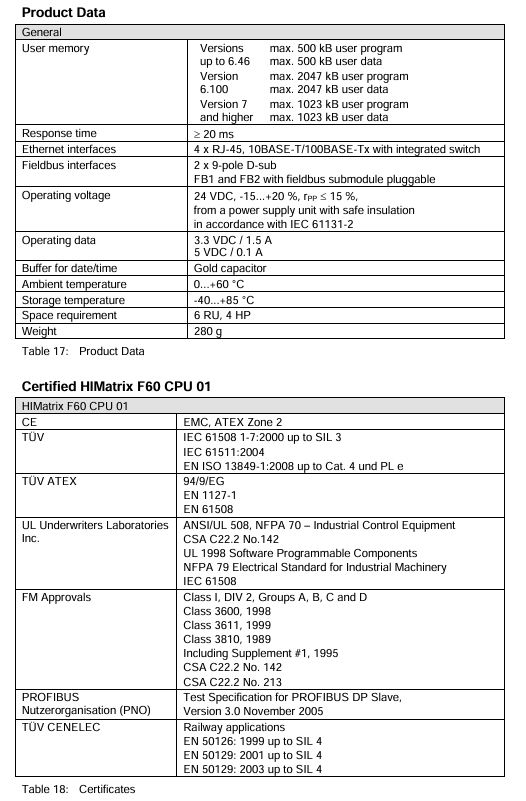
The module is certified by multiple international standards to ensure safety and integrity:
Power supply parameters: rated voltage 24VDC, allowable fluctuation range -15%~+20% (18~28.8VDC), ripple peak ≤ 15%; Working current: 3.3VDC/1.5A, 5VDC/0.1A.
Environmental restrictions: working temperature of 0-60 ℃, storage temperature of -40~85 ℃, pollution level II (IEC/EN 61131-2), altitude ≤ 2000m, no condensation.
Voltage monitoring: Built in voltage monitoring function, triggering an alarm (written to system variables) when<18VDC, and automatically shutting down when<13VDC.
3. Communication Protocol and Ports
(1) Support agreement
Safety related: Safe Ethernet.
Standard protocols: Modbus TCP, OPC, SNTP (time synchronization) TCP S/R; Ethernet/IP only supports CPU OS ≤ V6. x.
(2) Default network port
Port Type Port Number Purpose
UDP 8000 Programming Tool (PADT) Connection
UDP 8001 ELOP II Factory Remote I/O Configuration
UDP 8004 SILworX Remote I/O Configuration
UDP 6010 Secure Ethernet OPC
UDP 123 SNTP time synchronization
UDP/TCP 502 Modbus (user modifiable)
TCP 44818 EtherNet/IP Explicit Messaging Service
TCP 2222 EtherNet/IP data exchange
Safety operation standards
1. Electrostatic protection (ESD)
Operators must master ESD protection knowledge, wear anti-static wristbands during work, and ensure that the work area is free of static electricity interference.
When the module is idle or transported, it should be stored in the original factory anti-static packaging and direct contact with the circuit board is prohibited.
2. Installation and operation safety
Installation restrictions: Zone 2 scenarios must be placed in an enclosure with a protection level of IP54 or higher, and the enclosure must be labeled with “Only power-off operation allowed (except when explosion risk is excluded)”.
Cable requirements: Signal lines and power lines should be wired separately to avoid interference; Zone 2 installation must comply with DIN EN 60079-15/14 standards (terminals, wiring, creepage distance, etc.).
Prohibited behavior: live plugging and unplugging modules or cables; Operate the reset button during module operation; Replace core components with non original parts.
3. Emergency and residual risks
Emergency response: When the module fails, it automatically enters a safe state (input processing stops, output power is cut off), and any operation that prevents the safe operation of the system is prohibited.
Residual risks: may arise from engineering design defects, user program errors, wiring faults, and need to be avoided through compliant design and regular testing.
Installation and configuration process
1. Installation steps
(1) Basic installation (inside the rack)
In the power-off state, insert the module along the upper and lower rails of the rack, align it with the backplane slot, and press the front end board until the buckle “clicks” to lock.
Secure the module with screws on both sides of the front panel to ensure a secure installation.
Connection cables: Ethernet cable (RJ-45), fieldbus cable (D-sub, requiring sub module connection), power cord (powered by power module, no direct wiring required).
(2) Zone 2 Special Installation
Additional requirements: The enclosure protection level should be ≥ IP54 to ensure heat dissipation (the basic power consumption of the module is 6.5W, and it can reach 12W when equipped with a communication submodule).
Power requirements: PELV/SILV grade safety isolation power supply must be used, in compliance with IEC 61131-2 standard.
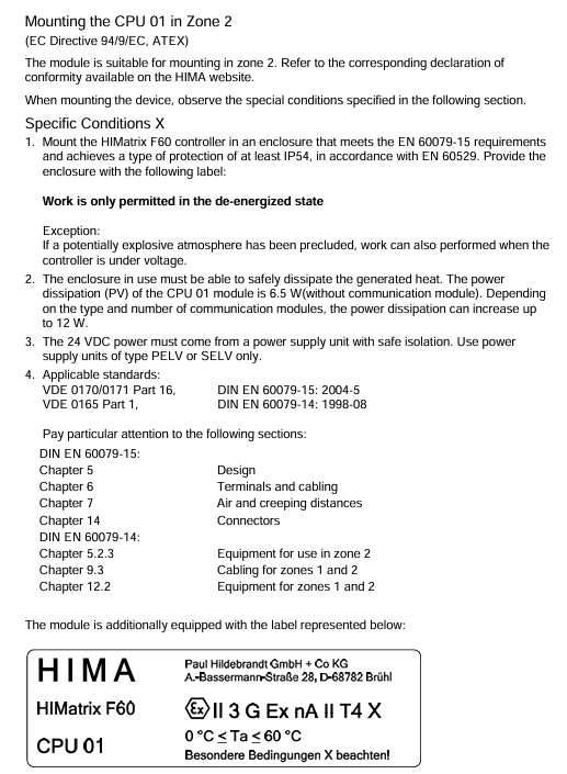
Label pasting: The shell needs to be pasted with ATEX compliant labels, and the module comes with an “Ex113GExnA II T4X” label.
2. Configuration process
(1) Tool selection and preliminary preparation
Confirm module OS version: Select the corresponding programming tool (ELOP II Factory/SILworX) based on the model label or front-end LED.
Reference documents: HIMatrix system manual (HI 800 191 E), safety manual (HI 800 023 E), and programming tool help documentation are required.
(2) Core configuration steps
Hardware Mapping: Create a project in the programming tool and configure the CPU module (Slot 2) and I/O module (Slot 3~8) according to the rack slot. There is a slight difference in slot numbers between SILworX and ELOP II Factory (refer to the table below). |Rack slot | SILworX slot number | ELOP II Factory slot number | Module type | | — | — | — | — | | | | | | 1 | – | PS 01 power module (no configuration required) | | 2 | 0 (CPU)/1 (COM) | – | CPU/communication module (integrated) | | | 3 | 2 | 1 | I/O module | | 4 | 3 | 2 | I/O module | | | 5~8 | 4~7 | 3~6 | I/O module|
Network configuration: Set the IP address (default 192.168.0.99) and subnet mask to ensure consistency with the PADT (programming computer) network segment; If modifications are required, they can be restored to default values through programming tools or reset functions.
Programming and downloading: Write user programs using IEC 61131-3 standard languages such as Function Block Diagram (FBD), compile them, and download them to the module Flash EPROM.
Security configuration: Set the watchdog time (WDT) and security cycle time according to the security manual, and configure security communication parameters (if applicable).
3. Reset operation (restore default settings)
Applicable scenario: Forgetting administrator account password or IP address conflicts with PADT.
Operation steps:
Disconnect the module power supply and unplug all fieldbus connectors (to avoid interfering with other devices).
Insert a needle shaped insulating material into the reset hole of the front end board, press and hold for ≥ 20 seconds, and at the same time, turn on the power to restart the module.
Reset effect: The IP address is restored to 192.168.0.99, the system ID (SRS) is restored to 6000.0.0, and only the default administrator account (empty password) is activated.
Note: In COM OS versions ≥ 10.42, after resetting, it is necessary to reconfigure the connection parameters and account before downloading the program/OS.
Operation and Diagnosis
1. Running status indication (LED interpretation)
The LED status of the module varies slightly with the CPU OS version, and its core meaning is as follows:
(1) System LED
Meaning of LED color status (CPU OS ≥ V8)
RUN green constantly on and running normally (STOP/RUN status)
RUN green Blinking1 (600ms on/off) is loading a new operating system
RUN green off, non RUN state
ERR red constant light lacks additional function authorization and testing mode
ERR red Blinking1 fault shutdown (hardware/voltage/configuration failure), requiring PADT restart
Confirm that the module is securely installed, the cable connections are correct, and there is no risk of static electricity.
Connect the power module to supply power, and the module will automatically perform LED self-test (all LEDs will briefly light up).
Start the programming tool and establish a communication connection with the module (via IP address).
Download user programs and configuration files to verify the validity of the configuration.
Switch the module to RUN state and confirm normal operation through LED and programming tools.
(2) Shutdown process
Normal shutdown: Use programming tools to switch the module to STOP state, and disconnect the power after the program stops.
Emergency stop: When the module fails, it automatically enters the ERROR STOP state, and after troubleshooting, it restarts through PADT.
3. Diagnostic methods
First level diagnosis: Determine the fault type based on the status of the front-end LED (such as ERR flashing=system fault, FAULT flashing=I/O fault).
Secondary diagnosis: By using programming tools to read diagnostic logs and system variables (such as power status and temperature status), locate specific fault points.
Common diagnostic items: communication failure (port/protocol configuration), invalid configuration (slot mapping error), hardware failure (voltage/module damage).
Maintenance and troubleshooting
1. Daily maintenance
Regular maintenance: Conduct a Proof Test every 10 years, refer to the HIMatrix Safety Manual (HI 800 023 E).
System update: Use downtime to upgrade the operating system through programming tools (first place the module in STOP state), and confirm the compatibility of the new version before upgrading.
Cleaning requirements: Wipe the outer shell with a dry soft cloth, and do not clean with water or chemical solvents; Regularly check that the cooling vents are unobstructed.
2. Fault handling
(1) Common faults and solutions
Possible causes and solutions for the fault phenomenon
The module cannot be started, ERR is constantly on and the voltage is too low. Check the power supply voltage (≥ 18VDC) for hardware faults and replace the module
Communication failure, Ethernet LED off, IP address conflict, cable damage investigation, IP conflict (communication LED synchronously flashing=conflict), replace network cable
Program cannot be downloaded, invalid PROG flashing configuration, incompatible OS version, verification slot mapping and configuration parameters, upgrading/downgrading OS
I/O unresponsive, FAULT flashing. I/O module fault, wiring error. Check the I/O module connection, rewire and test
There is no communication on the fieldbus, and the FB LED is off. The fieldbus submodule has not been installed, and a compatible fieldbus submodule has been installed
(2) Module replacement process
Disconnect the power supply module and unplug all connecting cables (Ethernet, fieldbus).
Loosen the module fixing screws and remove the module from the rack rail through the bottom handle.
Fix the new module according to the installation steps, connect the cables, and ensure that the wiring is consistent with the original module.
Connect the power, download the original configuration and program, and verify that it runs normally.
Attention: Only modules of the same model or HIMA authorized substitute models can be replaced, and mixing different variants (CPU 01/CPU 01 SILworX) is prohibited.
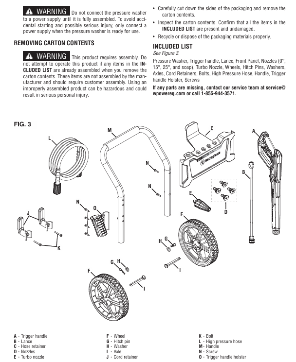
The comprehensive guidance document for the Westinghouse WPX3000e (3000 PSI maximum pressure/1.76 GPM maximum flow) and WPX3400e (3400 PSI maximum pressure/2.0 GPM maximum flow) electric high-pressure cleaning machines covers product safety specifications (such as prohibiting direct spraying of human/electrical objects, anti electric shock/anti freezing measures), detailed parameters, assembly steps (including installation of wheels, handles and other components), operating procedures (preparation before start-up, power on/off, nozzle selection and use), maintenance (cleaning, storage, replacement of vulnerable parts) and troubleshooting, while emphasizing the need for product registration to protect warranty rights.
Core parameters and configuration of the product
1. Comparison Table of Model Parameters
Parameter category WPX3000e WPX3400e
Water temperature requirement: Cold Water Only
Maximum pressure (PSI) 3000 3400
Rated pressure (PSI) 2600 3000
Maximum Flow Rate (GPM) 1.76 (6.7 LPM) 2.0 (7.57 LPM)
Prohibited scenarios: indoor/enclosed spaces (carbon monoxide free, this is electric, mainly to prevent electric shock), rainy/snowy/damp floors, near electrical appliances/combustibles (≥ 6 feet distance), using hot water (only cold water, hot water will damage pump seals).
Water source requirements: Only tap water is allowed, and the use of lake water, pool water, and swimming pool water (which can clog the filter) is prohibited. The inlet pressure should be ≤ 150 PSI.
2. Electrical safety
GFCI protection: The plug has built-in GFCI and needs to be tested monthly (press the TEST button to hear a “click” sound, then press RESET to reset). To replace the plug/wire, accessories with GFCI of the same specifications are required.
Extension cable restrictions (not recommended, use only when absolutely necessary):
Do not use damaged extension cords to avoid voltage drop causing motor overheating.
3. Operation taboos
It is prohibited to directly spray human bodies, animals, glass, and electrical appliances (which are prone to injury/damage/electric shock);
The pump body should not idle for more than 1 minute (after cutting off water), otherwise the motor/pump will overheat and be damaged;
Before disassembling the nozzle, it is necessary to stop the machine, release pressure (press the spray gun to release pressure), and lock the trigger;
Children are not allowed to operate it, and adults should avoid using it under the influence of alcohol/drugs.
Assembly steps
1. Key assembly process (tools required: screwdriver, wrench)
Wheel installation: Place the body on the side, pass the shaft through the wheel and washer → insert into the body bracket → fix with the shaft pin;
Install the handle: slide the handle into the slot of the body, press the buckle until it makes a “click” sound to ensure stability;
Wire clamp and nozzle holder: Align the holes of the wire clamp/nozzle holder and fix them on the side of the machine with screws;
Connect the spray gun and hose: One end of the high-pressure hose is connected to the threaded interface of the machine body (tighten the locking nut), and the other end is connected to the spray gun (insert after pulling the collar and tighten the locking nut).
Complete operational process
1. Preparation before startup
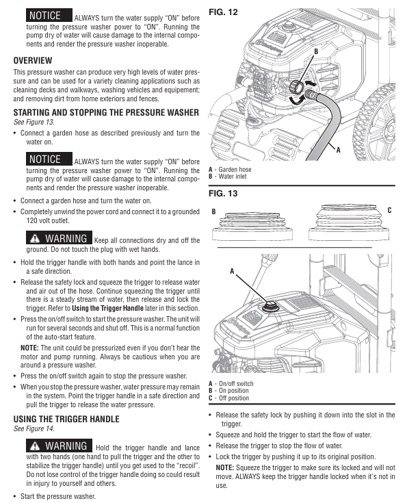
Water source connection: Connect the garden hose to the machine’s water inlet. First, rinse the hose for a few seconds to remove impurities and check the inlet filter screen (no damage/blockage);
Oil/Consumables: For the new machine, add 10W30 4-stroke engine oil (to the H-L range of the dipstick), and add a special high-pressure cleaning machine to the soap tank using a remover (dilute according to the instructions, do not use detergent/laundry detergent, as it may clog the nozzle);
Load check: Disconnect all nozzles, ensure trigger lock, and reset circuit breaker.
2. Startup and operation
Step operation details
1. Open the water source, press the trigger of the spray gun to release air until the water flow is stable (without bubbles), and then lock the trigger
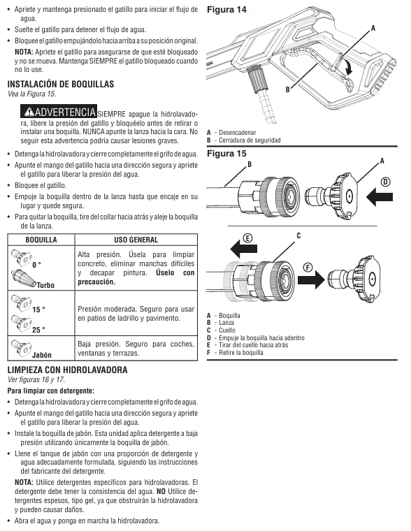
Plug in the GFCI plug and press the power switch to “ON”. The device will run for 1-2 seconds before shutting down (automatic start stop function, normal)
3 nozzle options: Install nozzle after shutdown and pressure relief (0 ° turbine for paint removal/concrete washing, 15 °/25 ° brick and stone washing, soap spray detergent)
Unlock the trigger, hold the gun with both hands (anti recoil), aim at the cleaning face, press the trigger to start spraying, and move from bottom to top to clean
3. Shutdown and Storage
Normal shutdown: Disconnect the nozzle → Run without load for 3-5 minutes to cool down → Press the power switch to “OFF” → Unplug the plug → Drain the water from the hose/pump;
Long term storage (over 30 days): Empty soap tank and rinse with clean water → Change engine oil → Remove spark plug and add 1 tablespoon of engine oil (lubricate cylinder) → Store in a dry and constant temperature place (anti icing/overheating, optional pump protector).
Maintenance and upkeep
1. Maintenance cycle and content table
Maintenance project maintenance frequency operation details
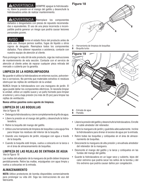
Before each use, remove the inlet filter and rinse it with clean water. If there is no damage, reinstall it
Spray nozzle cleaning every 50 hours/when clogged, use a nozzle cleaning tool/fine needle to pass through the nozzle hole and rinse with clean water in reverse
Clean the body with a soft cloth after each use, blow the vents with low-pressure air (≤ 25 PSI), and prohibit water flushing of electrical components
Lubricate the O-ring of the hose and clean it every 100 hours before applying Vaseline (non water soluble grease)
Replacement of vulnerable parts every 300 hours/replacement of nozzle, inlet filter screen, hose O-ring when damaged, recommended original accessories (such as turbine nozzle PWTN, filter screen 04000267-0)
2. Precautions
Waste engine oil/detergent cannot be dumped and must be disposed of according to EPA regulations;
Do not use flammable solvents such as gasoline to clean components and avoid corrosion;
Before maintenance, the power must be cut off, the pressure must be relieved, and the standby body must be cooled to room temperature.
Troubleshooting
Common troubleshooting solutions table
Possible causes and solutions for the fault phenomenon
The body is not powered on. 1. It is not grounded to a power source; 2. GFCI trips; 3. Damaged power cord. 1. Connect to a 120V grounded socket; 2. Press the GFCI reset button; 3. Contact after-sales service to replace the power cord
Running without water flow: 1. Wrong water source (not tap water); 2. nozzle blockage; 3. Spray gun malfunction 1. Replace with tap water; 2. Clean the nozzle; 3. Replace the spray gun
The connection between the hose and the spray gun is leaking, and the O-ring is missing/damaged. After stopping the machine and releasing pressure, replace the O-ring with the same specification
Stop the machine after 2 seconds of startup, unable to restart the automatic start stop function (pump pre pressure). Press the spray gun trigger to release pressure, and the machine will automatically start (normal phenomenon, not a fault)
Key questions and answers
Question 1: What are the differences in the use of extension cords between WPX3000e and WPX3400e? Why is there such a restriction?
Answer: The difference lies in the different specifications of the extension cord – WPX3000e requires the use of extension cords with a wire diameter of ≥ 16 AWG (American Wire Gauge) and a length of ≤ 50 feet; WPX3400e requires the use of extension cords with a wire diameter of ≥ 14 AWG and a length of ≤ 25 feet. The reason is that the rated current of the two models is different (WPX3000e is 13A, WPX3400e is 14A). The thinner and longer the wire diameter, the greater the resistance, which can easily lead to voltage drop, resulting in a decrease in motor power and overheating damage; WPX3400e has a higher current, so a thicker wire diameter and shorter length are required to reduce losses.
Question 2: What are the applicable scenarios for different nozzles when using a high-pressure cleaning machine? What are the consequences of making a wrong choice?
Answer: Different nozzles are suitable for the following scenarios:
0 ° Turbine Nozzle: High pressure mode, suitable for cleaning concrete, removing stubborn stains, and peeling paint (requires close range use, strong force);
15 °/25 ° nozzle: medium pressure mode, suitable for cleaning masonry tiles, exterior walls, and vehicles (moderate force to avoid scratches);
Soap nozzle: Low pressure mode, only used for spraying detergent (unable to suck soap under high pressure and easily causing detergent splashing and waste).
The consequences of choosing the wrong option: Cleaning the vehicle/wood with a 0 ° nozzle can cause surface scratches; The efficiency of using a medium pressure nozzle to treat stubborn stains is extremely low; Spraying Detergent in high-pressure mode can cause blockage of the soap circuit and even damage to the soap tank.
Question 3: What are the key steps to complete before storing a high-pressure cleaning machine for a long time? What is the purpose?
Answer: Long term storage (over 30 days) requires completing 5 key steps, with the following objectives and details:
Empty and rinse soap tank: Start the machine with clean water and spray it out with soap nozzle to prevent residual detergent from solidifying and blocking the soap path;
Change engine oil: Drain the old oil and add new 10W30 oil to prevent impurities in the old oil from corroding the crankcase components;
Lubricate the cylinder: Remove the spark plug, inject 1 tablespoon of engine oil, and pull the recoil handle several times to form an oil film on the cylinder wall and prevent long-term storage rust;
Drain water: Disconnect the water source and use the spray gun to drain the water from the hose/pump. The purpose is to prevent water from freezing and expanding in low-temperature environments, which may cause the pump body/hose to crack;
Constant temperature and dry storage: stored at ≥ 0 ℃ in a dry and ventilated place, with the purpose of preventing electrical components from being affected by moisture and short circuiting, as well as avoiding aging of pump seals caused by high temperatures.
Special configuration – non inflatable wheels, integrated rubber handle-
California compliance configuration optional CARB carbon canister optional CARB carbon canister standard CARB carbon canister
2. Core components and functions
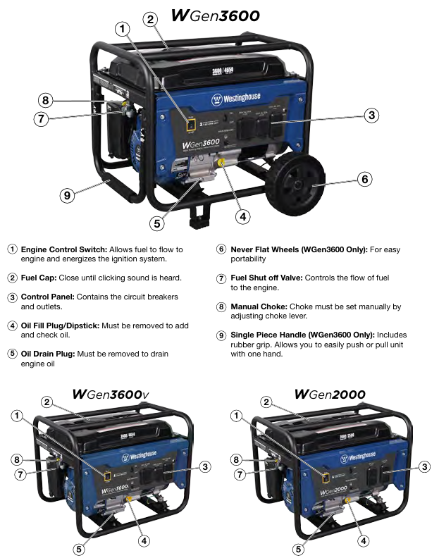
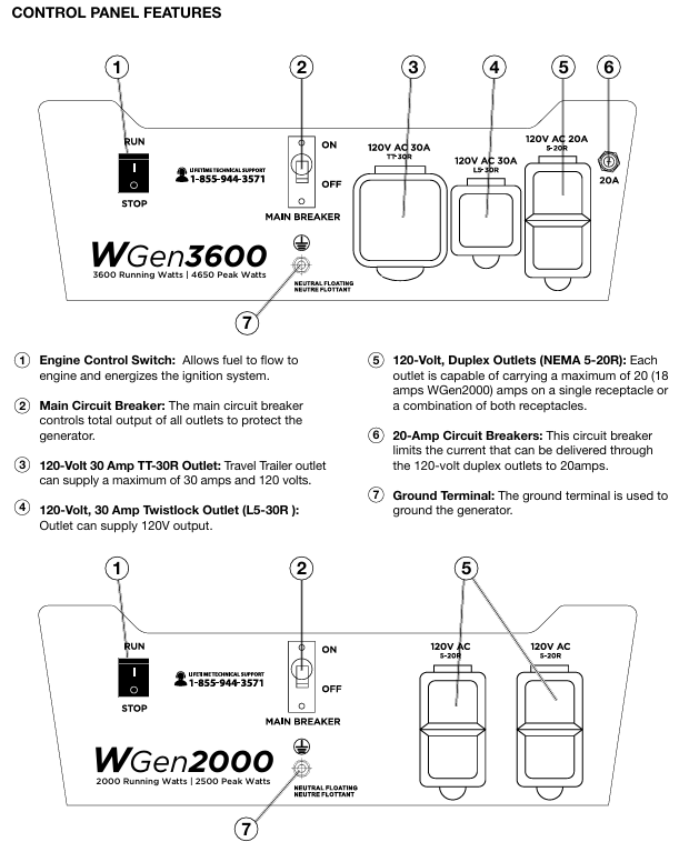
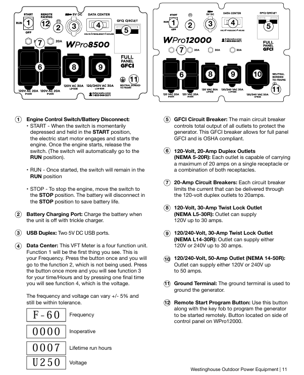
Control panel: including main circuit breaker, multiple power sockets (120V 20A dual socket, 120V 30A trailer specific socket, 120V 30A twist lock socket), grounding terminals, WGen2000 dual socket maximum load of 18A, other models are 20A.
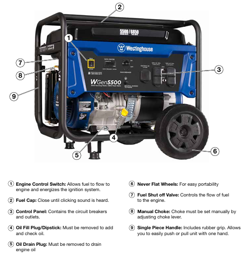
Engine components: including fuel tank (with oil level gauge), muffler and spark arrester (fireproof flower leakage), ignition coil assembly, throttle return spring, governor linkage device, etc.
Safety components: low oil level automatic shutdown switch (cutting off the engine when there is insufficient oil), circuit breaker (overload protection), GFCI socket (some models, anti leakage).
Safety operation standards (top priority)
1. Environmental safety requirements
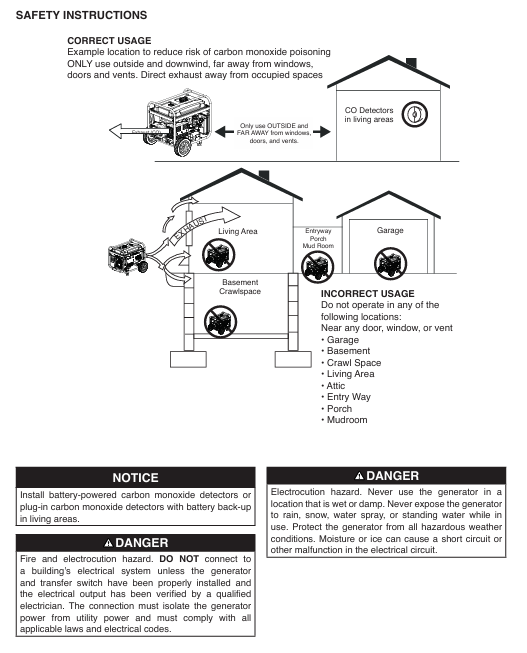
Only operate in outdoor ventilated areas, away from doors, windows, ventilation openings, and flammable materials. The minimum safe distance is 6 feet (1.8 meters). It is strictly prohibited to use indoors, in garages, or in enclosed spaces (engine exhaust contains carbon monoxide, colorless, odorless, and highly toxic).
It should be placed on a flat and hard surface, avoiding loose environments such as sand and grass (to prevent debris from blocking the air intake or cooling system); Do not use in rainy, snowy, humid environments or areas with accumulated water (to prevent short circuit and electric shock).
Avoid high temperature and high conductivity areas (such as metal decks, steel construction sites), and operate without open flames or sparks (such as cigarettes, matches, static power sources) around.
2. Fuel safety operation
Only use unleaded gasoline grade 87 and above, with an ethanol content not exceeding 10%. It is strictly prohibited to use 2-stroke engine oil, diesel, or other fuels.
Before refueling, the machine must be stopped and cooled to a surface that is not hot to the touch. Clean the surrounding area before opening the fuel tank cap and slowly refuel, not exceeding the neck of the refueling port (leaving space for fuel expansion).
If there is a fuel leak, immediately wipe it clean with a cloth and dispose of the cloth properly. Wait for the leaking area to dry before starting the generator; Wear goggles when refueling to avoid prolonged skin contact with fuel or inhalation of vapor.
Fuel containers should be stored in a well ventilated area, away from sources of ignition, and the use of gasoline as a cleaning agent is strictly prohibited.
3. Electrical safety operation
Before starting, it must be properly grounded: if used as a backup power source to connect to household circuits, a certified electrician must install a transfer switch and set up a grounding rod (in accordance with the national electrical code NEC and local regulations); Use grounding extension cords and three core/double insulated electrical appliances.
Do not touch the live terminals or exposed wires of the running generator, and do not operate with wet hands or when the generator is damp; Do not use damaged or aged power cords, and the plug should be fully inserted into the socket (the 240V socket should be fixed by rotating 1/4 turn clockwise).
Do not use generators to supply power to medical support equipment to avoid loads exceeding the rated power of sockets or circuit breakers.
4. Safety check before operation
Confirm that all loads have been disconnected (unplug external appliances and extension cords).
Check the engine oil level (new engines need to be filled with oil first, starting without oil will damage the engine).
Check the fuel quantity, whether the fuel pipeline leaks, and whether the air filter is clean.
Remove tools, cloths, and other debris placed during maintenance to ensure there are no obstacles around.
Complete operation process (start run stop)
1. Preparation before startup
Site selection: Outdoor ventilation, flat and hard, dry, away from combustibles and ventilation openings.
Grounding: Connect the grounding terminal as required (operated by an electrician when a grounding rod is required).
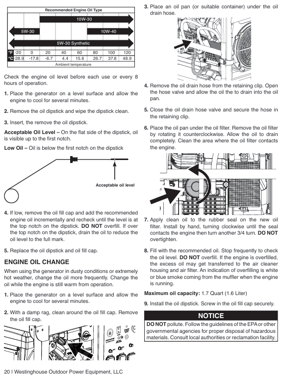
Oil inspection:
Engine oil: After cooling down the machine for a few minutes, clean the area around the oil filling port, take out the dipstick and wipe it clean, completely unscrew it, and then take it out again. The oil level should be between the H (high) and L (low) marks. If it is insufficient, add 10W30 4-stroke engine oil (to avoid excess).
Fuel: Ensure that the fuel tank has sufficient qualified gasoline and check if the fuel valve is closed (before starting).
Load disconnection: Disconnect all external electrical appliances and extension cords, and confirm that the circuit breaker is in the reset state.
2. Manual startup steps (applicable to all three models)
Reset circuit breaker: Set the main circuit breaker and branch circuit breaker to the “ON” position (reset if tripped previously).
Open the fuel valve: Switch the fuel shut-off valve to “ON” (ensure that fuel flows to the engine).
Adjust the air door: Turn the air door handle to the “ON” position (necessary for cold engine start-up, can be omitted for hot engine).
Start switch: Push the engine control switch to the “RUN” position.
Pull the recoil starter: Slowly pull the recoil handle until you feel an increase in resistance (compression stroke), then quickly pull upwards and slightly away from the generator direction, repeating until the engine starts.
Stable engine: After starting the engine, wait for the speed to stabilize and gradually turn the throttle handle back to the “OFF” position (to avoid unstable operation caused by excessive mixture).
Connect the load: After confirming that the generator is running smoothly, connect the electrical appliances one by one (the total load does not exceed the rated power).
3. Precautions during operation
Real time observation of operating status: If there is abnormal noise, excessive vibration, smoking, sparks, or overheating of the socket, immediately stop the machine for inspection.
Avoid overload: It is forbidden to connect multiple high-power electrical appliances at the same time. If the circuit breaker trips, disconnect the load first, cool down, and then reset to investigate the cause of overload.
Fuel replenishment: When there is insufficient fuel during operation, it is necessary to first shut down for cooling, and then refuel according to the requirements of fuel safety operation.
Altitude adaptation: For every 300 meters (1000 feet) increase in altitude, the engine power decreases by about 3.5%, and the power decrease is even more significant when the carburetor is not modified. High altitude use requires early modification of the carburetor.
4. Shutdown steps
Normal shutdown
Disconnect the load: First unplug all external appliances and extension cords.
No load cooling: Run the generator without load for 3-5 minutes to reduce the temperature of the engine and generator.
Turn off the engine: Set the engine control switch to the “STOP” position; If stored for a long time, first close the fuel valve and let the engine run until the fuel runs out before automatically stopping (clearing the carburetor to prevent fuel deterioration).
Emergency shutdown
When encountering risks of fire, leakage, electric shock, or engine abnormalities, simply turn the engine control switch to the “STOP” position without the need for idle cooling.
Maintenance and upkeep (extend lifespan+ensure safety)
1. Maintain safety prerequisites
Stop the machine and cool it down until the surface is not hot to the touch, then remove the spark plug cap (to prevent accidental start-up); The electric starter model requires disconnecting the negative cable of the battery.
Maintain good ventilation in the area, keep away from sources of fire, avoid skin contact with engine oil and fuel, and wear gloves and goggles.
Do not use gasoline or flammable solvents to clean components. Waste engine oil and cleaning fluids must be disposed of properly in accordance with EPA or local regulations and cannot be dumped.
2. Long term storage and maintenance (not used for more than 30 days)
Cleaning the body: Clean dust, debris, and oil stains according to daily cleaning requirements.
Handling fuel:
Method 1: Drain the fuel tank, open the fuel valve, start the engine until the fuel runs out, and automatically stop (empty the carburetor).
Method 2: Add fuel stabilizer, fill the fuel tank (reduce air contact), run for 10 minutes to circulate stabilizer to the carburetor, and close the fuel valve.
Change engine oil: Follow the oil change steps to replace the new engine oil to avoid the old oil from deteriorating and corroding the engine.
Protect the cylinder: Remove the spark plug, inject 1 tablespoon of clean engine oil, pull the recoil handle several times by hand (to evenly apply the oil to the cylinder wall), and reinstall the spark plug.
Storage environment: dry, ventilated, cool, away from sources of fire and corrosive substances. WGen3600 needs to remove the wheels or cushion the body to avoid tire deformation under pressure.
Regular inspection: Pull the recoil handle several times a month (without starting) to keep the components moving.
Common troubleshooting (problem cause solution)
1. Engine running but no power output
Potential cause solutions
The main circuit breaker or branch circuit breaker trips and disconnects all loads. Press the circuit breaker reset button and check if the load exceeds the rated power to avoid overload
The power cord plug is not fully inserted into the socket and needs to be unplugged again. The 240V socket needs to be rotated clockwise by 1/4 turn to ensure locking
Replace the damaged or faulty power cord with a new qualified power cord (matching the load power)
External electrical malfunction: Disconnect the faulty electrical appliance and connect it to a known normal low-power appliance (such as a desk lamp) for testing
GFCI socket trip (some models) Press the “reset” button on the GFCI socket
Internal circuit failure of generator: Contact Westinghouse authorized service dealer for repair
2. The engine cannot start or immediately stalls after starting
Potential cause solutions
If the fuel tank is empty or the fuel has deteriorated, add qualified gasoline. If the deteriorated fuel needs to be drained and the fuel tank and carburetor need to be cleaned
The fuel valve is not open. Switch the fuel valve to the “ON” position
Improper adjustment of the air door (too tight or too loose): Set the air door to “ON” when starting the cold engine and to “OFF” when starting the hot engine. Adjust it slightly according to the operating status after starting
Air filter blockage. Clean or replace the air filter according to maintenance steps
Insufficient engine oil triggers low oil level shutdown to replenish oil to the qualified level, restart the engine
The spark plug cap is not locked tightly. Press the spark plug cap firmly to ensure that it fully covers the top of the spark plug
Spark eliminator blockage, remove and clean. Spark eliminator carbon buildup
Electric starter models have insufficient battery power. Charge or replace the battery
3. Sudden engine shutdown during operation
Potential cause solutions
After running out of fuel and shutting down for cooling, add gasoline
If the oil level is too low, replenish the oil to the qualified range and check for any oil leaks
Overloading caused overload tripping and partial load disconnection. After cooling down, reset the circuit breaker and restart
Clean the debris in the cooling system after the engine overheats, ensure good ventilation, stop and cool down before restarting
Check the fuel pipeline and filter for blockage, and clean impurities
4. Unstable engine speed (shaking, fluctuating fast and slow)
Potential cause solutions
The air door is not closed (not adjusted after the refrigeration machine is started), gradually move the air door to the “OFF” position
Clean or replace the dirty air filter
Poor fuel supply (blocked pipelines, dirty filters) Clean the fuel pipelines and filters
Frequent switching of loads to avoid frequent starting and stopping of high-power electrical appliances, maintaining load stability (slight fluctuations are normal phenomena)
Check for looseness of the governor linkage and tighten the governor linkage. If necessary, contact the dealer for adjustment
Power and electrical parameters: operating power of 5500 watts, peak power of 6850 watts; Rated voltage 120/240V, frequency 60Hz, total harmonic distortion<23%; The operating current is 23 amperes and the peak current is 28 amperes.
Core configuration: 420cc OHV four stroke engine (13 horsepower), rated speed of 3600RPM; The fuel tank capacity is 25 liters (6.6 gallons), with a range of 20 hours under 1/4 load and 15 hours under 1/2 load; Oil capacity 1.1 liters, recommended SAE 10W30 oil; Spark plug model Torch F7TC, clearance 0.027-0.032 inches (0.70-0.80mm).
Structure and Function: Equipped with one 120/240V 30A twist lock socket (NEMA L14-30R) and two 120V 20A GFCI dual socket sockets (NEMA 5-20R); Including VFT data center (displaying voltage, frequency, and cumulative operating time); Equipped with 10 inch polyurethane wheel and single handle foam grip, easy to move; Net weight 174 pounds (88kg), supports transfer switch connection.
Environment and certification: certified by EPA, CARB, CSA; For every 1000 feet increase in altitude, the power decreases by 3.5%. For altitudes above 5000 feet, a high-altitude carburetor kit (part number 140545) must be installed; Operating noise of 72dBA, equipped with spark arrester.
Safety operation standards (core focus)
1. High risk warning and contraindications
Risk of carbon monoxide poisoning: It is strictly prohibited to use in enclosed/semi enclosed spaces such as indoors, garages, and basements. It can only be operated in outdoor ventilated areas and kept at least 15 feet (4.5 meters) away from doors, windows, ventilation openings, and air conditioning air intakes; Suggest installing a carbon monoxide detector.
Fire and explosion risks: The machine must be stopped and cooled down before refueling; Do not overfill (the oil level should not exceed the neck of the fuel tank filling port); Keep away from sources of fire, sparks (cigarettes, static electricity); When there is a fuel leak, wipe it clean immediately and wait for the area to dry before starting; Do not store fuel indoors during storage.
Electric shock risk: Do not use in damp environments, rainy or snowy weather; Do not touch live terminals and exposed wires during equipment operation; Use grounded three core extension cables and prohibit the use of damaged or aged cables; The connection to the building power grid must be installed by a certified electrician to ensure isolation from the mains power supply.
Other taboos: Not suitable for powering medical equipment; Prohibition of modifying equipment; Overloading operation is prohibited; Do not move or tilt the device while it is running; Prohibit starting with load.
2. General safety requirements
Ensure that there are no obstacles around the equipment during operation and avoid touching high-temperature components such as mufflers and engines (after cooling); Wear protective equipment (gloves, goggles) to avoid direct skin contact with engine oil and gasoline; Wash hands promptly after operation.
Before starting, all loads must be disconnected to avoid damaging the equipment during loaded startup; Grounding must comply with local regulations. If connecting to building systems, an electrician must confirm whether a grounding rod (copper wire ≥ 10 AWG) is required.
Before transportation, the equipment needs to be cooled down and kept level. If necessary, the fuel should be drained; When storing, keep away from sources of fire and heat (such as water heaters, stoves, etc.), and do not use wires or tools to cross the two poles of the battery (if it is an electric starting model).
Documents: User Manual, Quick Launch Guide, Product Registration Card.
(2) Assembly steps (requiring collaboration between two people to avoid single person handling)
Foot installation: Place the generator on a flat surface and fix the feet on both sides of the frame with M8 flange bolts to ensure a secure installation.
Wheel installation: Insert the axle pin through the washer and wheel into the frame axle bracket, ensuring that the bolt hole faces inward towards the generator; Lock the axle pin hole with an open-ended pin, and repeat the operation on the other side (the wheel is only used for manual movement, dragging or road driving is prohibited).
2. Preparation before startup
Location selection: Outdoor ventilated area, at least 15 feet (4.5 meters) away from buildings and combustibles, on a horizontal and dry surface, avoiding loose materials (sand, grass debris) to prevent blockage of air vents.
Oil inspection:
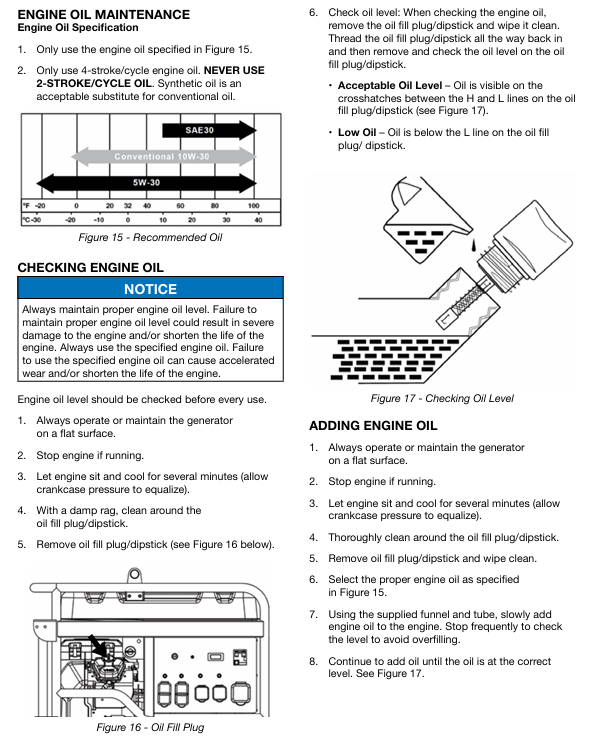
Engine oil: The new machine has no engine oil and needs to be added to the “MAX” mark on the dipstick (place the cold machine horizontally, wipe the dipstick dry, fully screw it in, and then remove it for inspection).
Fuel: Add unleaded 87-93 gasoline with ethanol content ≤ 10%; Clean the fuel tank after refueling and check for leaks.
Load and grounding: Disconnect all electrical equipment connections; Grounding must comply with local regulations. If connecting to building systems, an electrician must confirm whether a grounding rod is required.
3. Startup and shutdown operations
(1) Start the process
Turn the fuel valve to the “ON” position.
Cold machine: Turn the air damper to “ON”; Heat engine: Set the choke to “OFF”.
Push the engine control switch to ‘RUN’.
Slowly pull the recoil start rope until the resistance increases, and quickly pull upwards to start (the longest single pull should not exceed 5 seconds, failure should be attempted again with a 10 second interval).
After the engine starts, wait for the RPM to stabilize and gradually retract the choke to “OFF”.
Connect electrical equipment (following the principle of “high power first, low power later” to avoid overloading).
(2) Shutdown process
Normal shutdown: Disconnect all loads → Run without load for 3-5 minutes → Turn the engine control switch to “STOP” → Close the fuel valve; Long term non use requires closing the fuel valve and allowing the engine to run until it shuts down on its own (depleting the fuel in the carburetor).
Emergency stop: Simply turn the engine control switch to “STOP” (only used in case of malfunction or danger).
Key maintenance operation details
(1) Oil change
Place the refrigeration unit horizontally, clean the area around the oil discharge port, and place the oil pan.
Remove the oil drain plug, drain the old oil, close the drain plug and tighten it.
Add recommended engine oil to the “MAX” mark on the dipstick through the oil filler port, install the dipstick and filler cap, start the engine and check for leaks.
Waste engine oil should be disposed of according to environmental protection requirements and should not be dumped into sewers, ground or water sources at will.
(2) Evacuation of carburetor float (before long-term storage)
Stop the generator for cooling, keep away from sources of fire, and place a container under the carburetor.
Loosen the bottom screw of the carburetor float, drain the remaining fuel, and tighten the screw.
(3) Storage maintenance
Key points for storage duration operation
No special treatment is required within one month, keep the oil and fuel normal, and regularly check the fluid level
Clean the equipment after more than one month → Drain the fuel tank and carburetor float → Change the engine oil → Inject 1 tablespoon of engine oil into the spark plug hole, pull the starting rope to make the piston run (protect the cylinder wall) → Clean the spark arrester → Store in a dry and ventilated place, away from fire sources
Common troubleshooting
Possible causes and solutions for the fault phenomenon
The engine is running but there is no power output. 1. The circuit breaker has tripped; 2. The power cord is not securely plugged in; 3. Power cord/electrical equipment malfunction; 4. GFCI socket tripped; 5. Internal equipment malfunction: 1. Reset the circuit breaker and check for overload; 2. Re plug the plug (the 240V socket needs to be turned clockwise by 1/4 turn); 3. Replace the power cord or test the normal equipment; 4. Press the GFCI reset button; 5. Send to authorized service points
The engine cannot start/stalls after starting. 1. The fuel valve is closed; 2. Lack of fuel/deterioration of fuel; 3. Blockage of oil circuit; 4. The air filter is dirty; 5. Low oil level (low oil protection); 6. Spark plug malfunction/improper clearance; 7. Spark eliminator blockage 1. Open the fuel valve; 2. Add fresh fuel; 3. Clean the oil circuit; 4. Clean/replace the filter; 5. Add engine oil; 6. Adjust/replace spark plugs; 7. Clean the spark eliminator; If it is invalid, send it for repair
Sudden shutdown of generator: 1. Lack of oil; 2. Low oil level (low oil protection); 3. Excessive load 1. Oil replenishment; 2. Add engine oil; 3. Reduce load after restart; If it is invalid, send it for repair
Unstable engine operation/speed fluctuation 1. Air filter blockage; 2. Frequent load switching; 3. Equipment malfunction: 1. Clean the filter; 2. Load fluctuations are a normal phenomenon and do not require any handling; 3. Send to authorized service points
GFCI socket has no power. 1. The socket trips; 2. Socket malfunction: Press the reset button; 2. Send for repair and replacement of sockets
Fuel and engine oil fuel type: unleaded gasoline (87-93 octane, ethanol content ≤ 10%, E15/E85 prohibited); Fuel tank capacity: 64L (17 gallons); Oil capacity: 2.3L (2.4 US quarts); Recommended engine oil: SAE 10W-30 (can be replaced with 5W-30/10W-40/5W-30 synthetic oil at extreme temperatures)
Key component spark plug model: 97108 (F7TC); Gap: 0.024-0.032 inches (0.60-0.80mm); Voltage regulator: AVR; AC generator type: brushed
Maximum ambient temperature for environmental adaptation: 40 ℃ (104 ° F); Certification: EPA, CARB, CSA; Altitude impact: Power decreases by 3.5% for every 1000 feet increase
2. Control panel and output interface
Core functions: Data center (displaying voltage, frequency, cumulative operating time, maintenance reminders), 83A main circuit breaker, low idle switch (reducing fuel consumption and noise during intermittent loads, disabled for sensitive electronic devices).
Risk of carbon monoxide poisoning: It is strictly prohibited to use it in enclosed/semi enclosed spaces such as indoors, garages, and basements. It can only be operated in outdoor ventilated areas and kept away from doors, windows, ventilation openings, and air conditioning inlets. It is recommended to install carbon monoxide detectors.
Fire and explosion risks: The vehicle must be shut down and cooled down for at least 2 minutes before refueling; Do not overfill (the oil level should not exceed the red filling ring in the fuel tank); Keep away from sources of fire, sparks (cigarettes, static electricity); When there is a fuel leak, it is necessary to wipe it clean immediately and wait for the area to dry before starting.
Electric shock risk: Do not use in damp environments, rainy or snowy weather; Do not touch live terminals and exposed wires during equipment operation; Use grounded three core extension cables and prohibit the use of damaged or aged cables; The connection to the building power grid must be installed by a certified electrician to ensure isolation from the mains.
Other taboos: Not suitable for powering medical equipment; Prohibition of modifying equipment; Overloading operation is prohibited; Do not move or tilt the device while it is running.
2. General safety requirements
Maintain a clearance of at least 5 feet (1.5 meters) around the device during operation, including above; Avoid touching high-temperature components such as mufflers and engines (after cooling).
Wear protective equipment (gloves, goggles) to avoid direct skin contact with engine oil and gasoline; Wash hands promptly after operation.
Cool down for 30 minutes before transportation, keep it level, and if necessary, empty the fuel to prevent leakage; Keep away from sources of fire and heat (such as water heaters, stoves, etc.) during storage.
Battery maintenance: The battery contains sulfuric acid electrolyte (corrosive) and lead compounds, and protective equipment should be worn during operation; No smoking or proximity to fire sources; Prohibit wires and tools from crossing the two poles of the battery; If the acidic solution comes into contact with the skin, immediately rinse with water and apply baking soda to neutralize it.
Documents: User Manual, Quick Launch Guide, Product Registration Card.
(2) Assembly steps (requiring collaboration between two people to avoid single person handling)
Wheel installation: Place the generator on a horizontal surface, insert the axle pin through the washer and wheel, insert it into the frame axle bracket, fix it with an open pin, and repeat the operation on the other side (the wheel is only used for manual handling and dragging is prohibited).
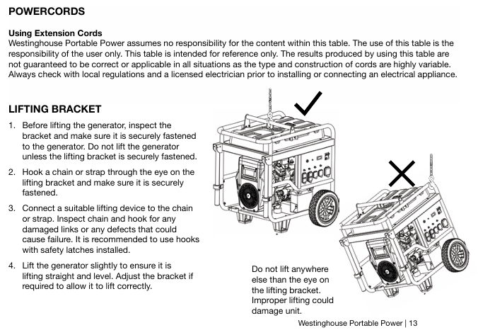
Installation of lifting hook: Align the top fuel tank bracket with the lifting hook and tighten it with 4 M8 flange bolts (only used for lifting or fixing the binding strap, do not grip other components for handling).
Battery installation: First, connect the red positive cable to the positive pole of the battery and cover it with a protective sleeve, then connect the black negative cable; Use insulated tools to avoid short circuits between the positive and negative poles.
2. Preparation before startup
Location selection: Outdoor ventilated area, at least 5 feet away from buildings and combustibles, on a horizontal dry surface, avoiding loose materials (such as sand and grass debris) to prevent blockage of air vents.
Oil inspection:
Engine oil: The new machine has no engine oil and needs to be added to the “MAX” mark on the dipstick (place the cold machine horizontally, wipe the dipstick dry, fully screw it in, and then remove it for inspection).
Fuel: Add unleaded 87-93 gasoline with ethanol content ≤ 10%; Clean the fuel tank after refueling and check for leaks.
Load and grounding: Disconnect all electrical equipment connections; Grounding must comply with local regulations. If connecting to building systems, an electrician must confirm whether a grounding rod (copper wire ≥ 10 AWG) is required.
3. Startup and shutdown operations
(1) Start the process
Turn the fuel valve to the “ON” position.
Cold machine: fully pull out the air damper; Heat engine: Set the choke to the middle or “RUN” position.
Press the start switch to “START” and hold for up to 5 seconds (to avoid overheating of the starter motor); After successful startup, release and warm up for 3-5 minutes.
After the engine runs steadily, slowly push back the choke to the “RUN” position.
(2) Shutdown process
Normal shutdown: Disconnect all loads → Run without load for 3-5 minutes → Turn the switch to “OFF”; Long term non use requires closing the fuel valve and allowing the engine to run until it shuts down on its own (running out of carburetor fuel).
Emergency stop: Simply turn the switch to “OFF” (only for use in case of malfunction or danger).
Key maintenance operation details
(1) Oil change
Place the refrigeration unit horizontally, clean the area around the oil filling port, and place the oil pan.
Remove the oil drain hose, open the valve to drain the oil, close the valve and secure the hose.
Disassemble the old oil filter counterclockwise and clean the installation surface; Apply a small amount of engine oil to the rubber sealing ring of the new filter, manually tighten it until it fits snugly, and then tighten it 3/4 turn (do not overtighten).
Add recommended engine oil to the “MAX” mark on the dipstick, install the dipstick and filler cap, start the engine and check for leaks.
(2) Battery maintenance
Charging: The generator can recharge the battery after running for 30-60 minutes; Long term use of the included trickle charger (connected to the control panel charging port), red light charging in progress, green light fully charged.
Replacement: First disconnect the negative cable, then disconnect the positive cable; The installation sequence of new batteries is reversed (connect the positive electrode first), part number 511075 (36AH), and used batteries need to be disposed of according to local regulations.
(3) Storage maintenance
Key points for storage duration operation
No special treatment is required within one month to maintain normal oil and fuel levels
Add fresh fuel and fuel stabilizer every 2-6 months, and empty the carburetor float
Drain the fuel tank and carburetor fuel after more than 6 months; Change the engine oil; Inject 1 tablespoon of engine oil into the spark plug hole, pull the starting rope to make the piston run (protect the cylinder wall); After cleaning the equipment, store it in a dry and ventilated place, and do not cover it with plastic sheeting (which is prone to moisture and rust)
Common troubleshooting
Possible causes and solutions for the fault phenomenon
The engine cannot start. 1. The battery switch is turned off or running low; 2. Insufficient/deteriorated fuel; 3. Air filter blockage; 4. Low oil level (low oil protection); 5. Spark plugs are damp/faulty/have improper clearances; 6. Fuel filter blockage 1. Turn on the battery switch or charge; 2. Add fresh fuel; 3. Clean/replace the filter; 4. Add engine oil; 5. Dry/replace spark plugs and adjust clearances; 6. Replace the fuel filter
Immediately turn off the engine after starting. 1. Fuel is depleted; 2. Abnormal oil level; 3. The air filter is dirty; 4. Fuel pollution; 5. Low oil level switch fault: 1. Add oil; 2. Check the oil level; 3. Clean the filter; 4. Drain the deteriorated fuel; 5. Contact customer service
No power output 1. Circuit breaker tripped; 2. Load overload; 3. Power cord/electrical equipment malfunction; 4. Internal fault of the generator: 1. Reset the circuit breaker to reduce the load; 2. Disconnect some equipment; 3. Replace the power cord or test the normal equipment; 4. Send to authorized service points
Insufficient engine power/unstable operation 1. Air filter blockage; 2. Fuel deterioration/filter blockage; 3. Overloading; 4. Aging of spark plugs; 5. Abnormal valve clearance: 1. Clean/replace the filter; 2. Replace the fuel and filter; 3. Reduce load; 4. Replace the spark plug; 5. Adjust the valve clearance
Remote start failure (if supported): 1. Remote control battery runs low; 2. Exceeding the remote control distance (≤ 100 feet); 3. Not paired. 1. Replace the remote control battery; 2. Get close to the generator; 3. Re pair (long press the panel pairing button+remote control start/stop button)
This document is the official user manual for Westinghouse’s two portable generators (WPro8500, WPro12000), covering the entire process from safe operation to maintenance troubleshooting, as well as product registration, after-sales support and other service information. It emphasizes the “continuous product improvement policy” and reserves the right to modify specifications. Some images may vary due to model differences.
2. Technical specification comparison
Model Running Watts Peak Watts Fuel Tank Capacity (L/G) Rated RPM Ignition Type Spark Plug Engine Displacement (cc) Stroke x Bore Oil Capacity (L) Oil Type THD
Note: Both generators do not require altitude carburetor modification. For every 300 meters (1000 feet) increase in altitude, the engine horsepower decreases by approximately 3.5% (the decrease is more significant without carburetor modification). For altitude kits, please contact the service team.
Safety warnings and regulatory requirements
1. Core security warning
California Proposition 65 Warning: ① Engine exhaust contains chemicals known to cause cancer, birth defects, or reproductive harm; ② Some components of the product and related accessories contain harmful chemicals of the same type, and hand washing is required after operation.
DANGER level risk:
Do not use in damp/rainy/snowy environments to avoid short circuits or malfunctions;
It is prohibited to operate in a confined space. The exhaust contains carbon monoxide (colorless, odorless, and toxic), and can only be used outdoors and away from doors, windows, and ventilation openings.
Warning level risk:
Electric shock risk: A certified electrician is required to connect to the power grid, use grounding extension cords, and avoid touching live terminals/operating with wet hands;
Gasoline risks: refuel in outdoor ventilated areas, refuel after cooling down, do not overfill (leave room for expansion), stay away from fire sources;
Equipment abnormality: It is prohibited to operate when the load overheats/output drops/sparks/smoke occur, and it is also prohibited to supply power to medical equipment.
2. Definition of Security Terms
Meaning of Terms
DANGER’s failure to avoid may result in death or serious injury
Warning: Failure to avoid may result in death or serious injury
CAUTION may cause minor/moderate injuries if not avoided
NOTICE may cause equipment/property damage or abnormal operation
NOTE: Necessary operations/conditions to ensure the normal operation of equipment
Unpacking and assembly process
1. Open box contents
Model includes items
WPro8500 ① User Manual; ② Quick Start Guide/Maintenance Plan; ③ Lift bracket (1 piece); ④ Wireless remote control (1 unit); ⑤ 1.1L SAE 10W30 engine oil (1 bottle); ⑥ Spark plug socket wrench (1 piece); ⑦ Wheel kit accessory box; ⑧ Funnel (1 piece)
WPro12000 ① User Manual; ② Quick Start Guide/Maintenance Plan; ③ Wireless remote control (1 unit); ④ 1.6L SAE 10W30 engine oil (1 bottle); ⑤ Spark plug socket wrench (1 piece); ⑥ Wheel kit accessory box; ⑦ Funnel (1 piece)
Place the generator on a horizontal surface, elevate the rear with wooden blocks, and install the support feet with M8 flange bolts;
The axle pin passes through the washer and the wheel, and is installed through the frame axle bracket. The split pin is fixed, and the other side of the wheel is operated repeatedly;
Attention: Before assembly, the engine oil and fuel must be drained. The wheel kit is only applicable to this generator and is not allowed for road use.
Battery installation (key steps for preventing electric shock):
Confirm that the positive (red) cable is securely fastened to the positive pole of the battery and covered with a protective cover;
Remove the protective packaging of the negative (black) cable terminal, disconnect the cable tie and lead it to the negative pole;
Open the black sleeve, tighten the negative cable, and then put back the protective sleeve;
Rule: Connect the power first and then the negative, disconnect the power first and then the negative, prohibit metal tools from crossing the two poles, and use insulated tools for operation.
Installation of lifting bracket (WPro8500 only): Align the bracket on the top of the fuel tank and fix it with 4 M8 flange bolts.
Operation Guide
1. Preparation before startup
Location selection: Outdoor ventilation, level and solid surface, at least 6 feet (1.8 meters) away from buildings/combustibles, away from doors, windows/ventilation openings.
Environmental requirements: Do not operate on rainy/snowy days, operate on dry surfaces to avoid loose materials (sand/grass debris) blocking the air vents.
Load and grounding: Disconnect all loads (unplug extension wires) before starting; A certified electrician is required to determine whether a grounding rod is needed (usually required when connecting the backup power supply to the transfer switch), and connect the control panel grounding terminal with a ≥ 10 AWG copper wire for grounding.
2. Fuel and oil requirements
Fuel: Only use unleaded gasoline, ethanol content ≤ 10%, octane rating ≥ 87; Stop the machine for cooling before refueling, ensure that the oil level does not exceed the neck of the filling port, and check for leaks after refueling.
Engine oil: The new engine has no engine oil, and 10W30 engine oil must be added before the first start-up (5W30 in winter and SAE30 in summer); Check the liquid level of the refrigeration unit, which should be between the H (high) and L (low) marks on the dipstick.
Electric start 1. Confirm that the engine oil is sufficient and the battery is connected; 2. Reset the circuit breaker; 3. Turn the fuel valve to ON; 4. Press the switch to START and release it after starting (automatic return to RUN). Both options are applicable. If it does not start for 5 seconds, release it and retry after 15 seconds; Charging when the battery is depleted
Backlash start 1. Same as 1-3 above; 2. Slowly pull the rope until the resistance increases, and quickly pull it upwards away from the generator. When only the WPro8500 battery runs out of power/disconnects, manually turn on the choke and turn it off after starting
Remote start 1. Turn the switch to RUN; 2. Long press the REMOTE PAIRING button on the panel for 3 seconds; 3. Long press the STOP button on the remote control until the indicator light flashes, and then long press the START button until it flashes; 4. Press and hold the PAIRING key for 3 seconds to complete pairing; 5. Press the START button on the remote control to start both models, with an effective distance of ≤ 100 feet (affected by battery level). After starting, there will be a 15 second delay in output
4. Stop method
Normal stop: 1 Disconnect all loads; 2. Cooling during no-load operation; 3. Turn the switch to OFF; 4. Close the fuel valve (allow the carburetor to run out of fuel during long-term storage).
Emergency stop: Simply turn the engine control switch to OFF.
Special maintenance operation
Oil change: When the engine is in a cold state, drain the oil from the oil pan through the oil drain plug, remove the plug and drain, then reinstall and add oil to the standard level.
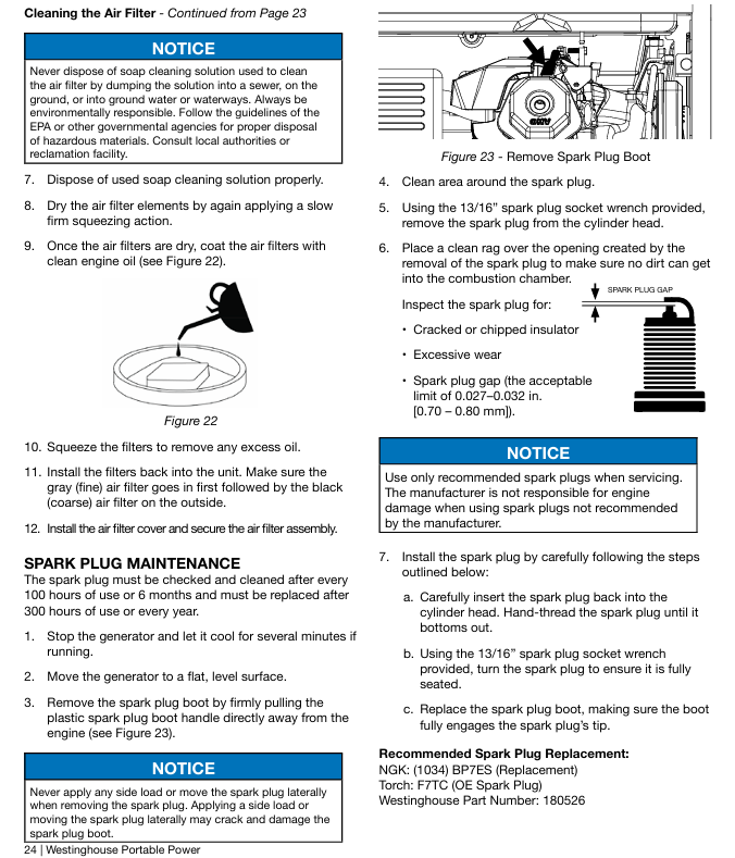
Air filter cleaning: Remove the cover and take out the filter cotton, clean with household detergent and warm water, squeeze and drain (do not twist), air dry, apply a thin layer of cleaning oil, and reinstall according to the “fine filter (ash) inside, coarse filter (black) outside”.
Spark plug maintenance: Remove the spark plug with a spark socket wrench, check the insulation layer for cracks and a gap of 0.027-0.032 inches (0.60-0.80mm), clean and reinstall it; Recommended replacement models: AC Delco 4EXLS, Autolite 52, Champion N9YC, Bosch W7DC, Torch F7TC.
Battery maintenance: Start the generator every 2-3 months and charge it for 15 minutes, or connect the charger to the charging port (RUN mode) for charging; The replacement model is as follows:
Model Westinghouse Part Number Compatible Battery Model Voltage (V) Capacity (Ah) Size (inches)
The engine is running but there is no power output. 1. The circuit breaker has tripped; 2. The power plug is not securely plugged in; 3. Power cord malfunction; 4. Electrical equipment malfunction; 5. GFCI trips; 6. Internal equipment malfunction: 1. Reset the circuit breaker and check for overload; 2. Re plug (the 240V plug needs to be turned clockwise by 1/4 turn); 3. Replace the power cord; 4. Connect to normal equipment testing; 5. Reset the GFCI circuit breaker; 6. Send to authorized service points
The engine cannot start/stalls after starting. 1. The fuel valve is closed; 2. Lack of gasoline; 3. Fuel pipeline blockage; 4. The startup battery runs out of power; 5. The air filter is dirty; 6. Low oil level (low oil protection); 7. Spark plug not tightened/faulty; 8. Fuel deterioration: 1. Open the fuel valve; 2. Add gasoline that meets the requirements; 3. Check and clean the fuel passage; 4. Charging (electric start only); 5. Clean/replace the air filter; 6. Add engine oil to the standard level; 7. Tighten/replace spark plugs; 8. Drain the deteriorated fuel and add new fuel
Remote start failure: 1. The remote control battery is dead; 2. Exceeding the remote control distance (>100 feet); 3. The remote control is not paired with the generator. 1. Replace the remote control battery; 2. Close to the generator (≤ 100 feet); 3. Follow the pairing process again
Sudden shutdown of generator: 1. Lack of fuel; 2. Low oil level (protective shutdown); 3. Excessive load; 4. Internal equipment malfunction: 1. Add gasoline; 2. Add engine oil; 3. Reduce load after restart; 4. Send to authorized service points
Product drawings
Explosion view: WPro8500 (page 26), WPro12000 (page 31) complete machine parts breakdown, including part numbers and names (such as generator assembly, fuel tank, control panel, etc.).
Engine view: Position markings and part numbers for the internal structures (pistons, connecting rods, valves, ignition coils, etc.) of two engine models.
Schematic diagram: Schematic diagram of electrical system (voltage regulator, wiring harness), fuel system (carbon canister, oil pipe) and other connections.
Power parameters: gasoline mode – rated power 3700W, peak power 4500W; propane mode – rated power 3330W, peak power 4050W, supports 120V single-phase output, frequency 60Hz, total harmonic distortion ≤ 3% (suitable for sensitive electronic devices).
Power configuration: 224cc engine, supports manual start, electric start, remote start (up to 30 meters), fuel tank capacity of 12.8L (3.4 gallons), oil capacity of 0.6L (0.63 US quarts), recommended oil model 10W-30.
Fuel compatibility: Gasoline requires octane rating of 87-93 (ethanol content ≤ 10%, E15/E85 prohibited); Propane supports standard gas cylinders with overcharge protection device (OPD) and is compatible with hose connections.
Environmental adaptability: The working temperature range is -9.4 ° C~50 ° C (5 ° F~122 ° F), with a maximum ambient temperature of 40 ° C (104 ° F). The power decreases by 3.5% for every 1000 feet (approximately 305 meters) increase in altitude.
2. Core positioning and advantages
Dual fuel flexible switching, higher power in gasoline mode, cleaner and safer storage in propane mode, suitable for different usage scenarios.
With the support of frequency conversion technology, low noise (in ECO mode) and low harmonic distortion, it can safely supply power to sensitive electronic devices such as computers and televisions.
Equipped with multiple safety protections (low fuel automatic shutdown, overload protection, CO sensor automatic shutdown), outdoor use is more reassuring.
Supports parallel operation (requires separate purchase of parallel lines), can be combined with compatible Westinghouse generators to increase total output power.
Core functions and operation guide
1. Core functional features
Dual fuel switching: The control panel is equipped with a fuel selection switch, which supports switching during operation (propane cylinders need to be connected in advance). During switching, the engine may briefly become unstable, which is a normal phenomenon.
Startup method:
Remote start: Use the matching keychain remote control with an effective distance of 30 meters and a 2-cell CR2016 battery model.
Electric start: First, turn on the battery switch and press the start button on the control panel.
Hand pulled start: Suitable for when the battery is low, slowly pull the rope until there is resistance and then quickly pull it.
ECO mode: After being turned on, the engine speed automatically adjusts with the load, reducing fuel consumption and noise, suitable for low-power continuous loads (such as lamps and computers); It is recommended to turn off ECO mode for high-power devices such as air conditioning and water pumps.
safeguard:
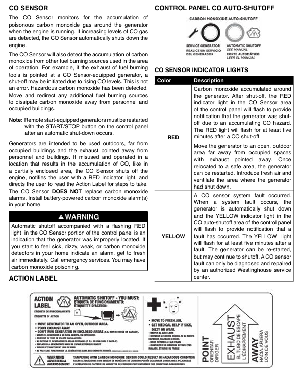
CO sensor: monitors the concentration of carbon monoxide in the surrounding area, automatically shuts down when it exceeds the standard, and the red indicator light flashes to give an alarm.
Low oil protection: When the oil level is below the safe value, it will automatically shut down and light up the low oil indicator light.
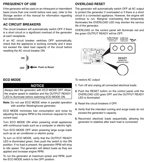
Overload protection: When the load exceeds the rated power, the circuit breaker trips, the overload indicator light lights up, and a power-off reset is required.
Output configuration: The control panel includes a 20A dual socket (NEMA 5-20R), a 30A RV dedicated socket (NEMA TT-30R), two 5V/2.1A USB interfaces, and supports parallel operation interfaces (requiring dedicated parallel wires).
2. Key operational steps
(1) First use preparation
Add engine oil: The new machine has no engine oil and needs to be filled with the recommended 10W-30 engine oil to the L-H mark on the dipstick. Overfilling is prohibited.
Connecting fuel:
Gasoline: Open the fuel tank cap and add 87-93 gasoline to the red filling ring in the tank. Do not overfill and tighten the fuel tank cap.
Propane: Connect one end of the matching hose to the propane interface of the generator (manually tighten, no need for raw material tape), and the other end to a gas cylinder. Use soapy water to check if the interface leaks (if it bubbles, it is a leak and needs to be re tightened).
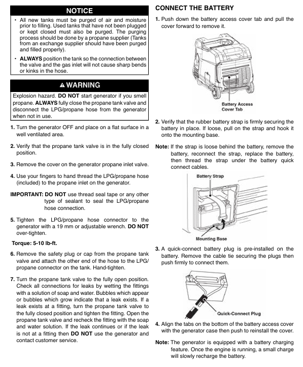
Connect the battery: Open the battery compartment cover, connect the quick connector, and ensure that the battery is securely fixed.
(2) Start operation
Gasoline mode: Turn the fuel selection switch to gasoline mode → open the fuel tank valve → press the start button (or remote start, manual start) → wait for the output ready indicator light (green) to light up, then connect the load.
Propane mode: Turn the fuel selection switch to propane mode → fully open the cylinder valve → press the start button → connect the load after the output is ready.
(3) Shutdown and fuel switching
Normal shutdown: First disconnect all loads → let the generator run without load for a few minutes → press the stop button (or turn off the battery switch) → in propane mode, the gas cylinder valve needs to be closed.
Fuel switching (in operation):
Gasoline propane cutting: Open the cylinder valve → switch the fuel switch to propane mode → close the fuel tank valve.
Propane to gasoline: Open the fuel tank valve → switch the fuel switch to gasoline mode → close the cylinder valve.
Installation and usage specifications
1. Installation and placement requirements
It must be used outdoors with good ventilation, at least 5 feet (about 1.5 meters) away from doors, windows, and ventilation openings. It is prohibited to use it indoors, in garages, basements, and other enclosed spaces to prevent carbon monoxide poisoning.
Place on a dry, flat, hard surface to avoid sand, grass debris, and other debris blocking the heat dissipation outlet. Leave a ventilation space of 5 feet (about 1.5 meters) around it.
Grounding requirements: If connecting to the building power supply system, a professional electrician must install a conversion switch and ground it; When only using a socket for power supply, there is no need for additional grounding (neutral line floating design).
2. Extension cords and load usage
Extension cables should use outdoor dedicated and grounded 3-core wires, with wire diameter specifications that match the load and length (recommended wire diameter ≥ 12AWG and length ≤ 50 feet for 20A loads).
Load management: All loads need to be disconnected during startup, and connected sequentially after startup. First, connect high-power devices (such as refrigerators and air conditioners), and then connect low-power devices to avoid overloading caused by starting multiple high-power devices at the same time.
Power adaptation: The total operating power should be ≤ rated power, and the starting power should be ≤ peak power (for example, if the starting power of a 1/3 horsepower water pump is about 2000W, sufficient margin should be reserved).
3. Parallel operation (parallel wires need to be purchased separately)
Only compatible Westinghouse variable frequency generators can be connected in parallel, with a total rated power of up to 7400W (dual engine gasoline mode).
Operation steps: Turn off two generators → Connect parallel wires (black to black interface, red to red interface, green grounding wire) → Start two generators in sequence → Connect the load after the output is ready, and prohibit parallel connection in ECO mode.
Maintenance and upkeep
1. Regular maintenance schedule
Maintenance project cycle operation content
Check the oil level before each use or after every 8 hours of operation, and replenish it if it is below the L mark
25 hours or 1 month after the first oil change; After heating up every 50 hours or 6 months, drain the oil and replace it with new oil. When installing the drain bolt, replace the copper washer
Clean the air filter Take out the foam filter element every 50 hours or 6 months, clean it with detergent, dry it and soak it with engine oil (squeeze out the excess engine oil) Reinstall
Spark plug maintenance check every 100 hours; Replace inspection gap (0.60-0.80mm) every 300 hours or 1 year, clean carbon deposits, and replace if damaged (recommended model F7RTC)
Clean the Mars extinguisher every 100 hours or 6 months. Remove the muffler cover, clean the carbon buildup on the filter screen, and replace it if it is damaged
When the battery is not used for a long time, it should be charged for 8 hours per month using the matching charger (no more than 8 hours to avoid overcharging)
2. Storage specifications
Short term storage (within 1 month): No special handling is required. Close the fuel valve and place it in a dry and ventilated place, covered with a dust cover (plastic cover is prohibited to avoid moisture).
Mid term storage (2-6 months): Add fresh fuel and fuel stabilizer, empty the carburetor float chamber of fuel, and disconnect the battery connector.
Long term storage (more than 6 months): Drain the fuel tank and carburetor, inject a small amount of engine oil into the cylinder, pull the pull rope to put the piston in the compression stroke (close the valve), disconnect the battery, and store in a dry and ventilated place.
Safety precautions
1. Core security warning
Risk of carbon monoxide poisoning: Only for outdoor use, keep away from doors, windows, and ventilation openings. Install a carbon monoxide alarm at home. If symptoms such as dizziness and nausea occur, immediately move to fresh air and seek medical attention.
Fire and explosion risks: Smoking and staying away from open flames are prohibited when refueling. Contact with mufflers (high temperature) is prohibited when heating up. Propane cylinders should be placed upright on the ground, away from heat sources and direct sunlight.
Electric shock risk: Do not use in damp environments or rainy days. Do not touch the socket when your hands are wet. The equipment should be placed in a dry place to avoid water accumulation.
2. Fuel safety
Gasoline storage: Use approved gasoline containers, store in a well ventilated area, away from sources of ignition, and prohibit long-term storage in the generator fuel tank.
Propane use: Check that the hose is not damaged or bent, close the cylinder valve after use, disconnect the hose during transportation, and fix the cylinder upright.
Troubleshooting
Unable to start without engine oil, fuel not turned on, spark plug wet/carbon deposits. Add engine oil, open fuel valve, dry or replace spark plug
Immediately stop the machine after starting, low oil, CO sensor alarm, overload and replenish oil, move to a ventilated area, and disconnect the overload load
No output power circuit breaker tripping, excessive load, socket fault resetting circuit breaker, reducing load, checking socket connection
Unstable operation, fuel impurities, clogged air filter, insufficient propane pressure. Replace with fresh fuel, clean air filter, and check propane cylinder pressure
Poor performance in propane mode due to low cylinder temperature and hose leakage. Move to a warm environment and check the leak point with soapy water and tighten it
1. Product series division and applicable scenarios
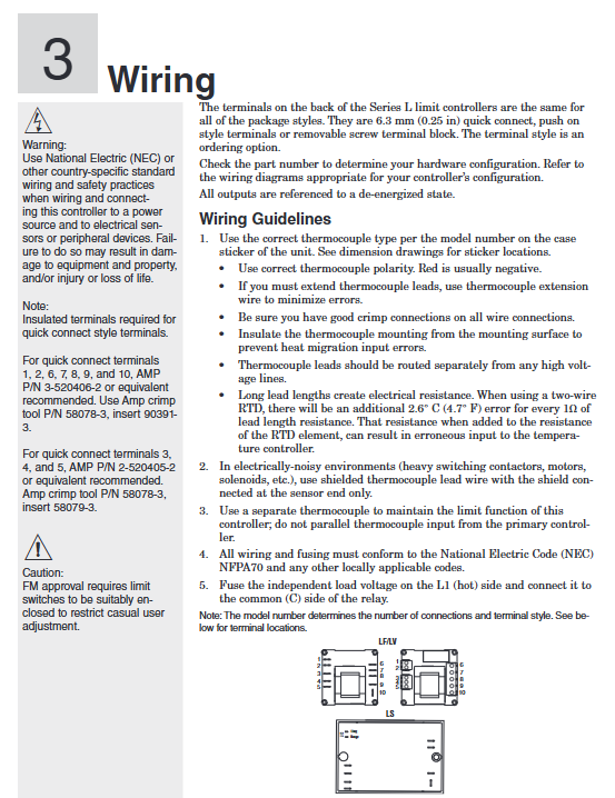
The Watlow Series L series is divided into three sub series: LF, LV, and LS, all of which are industrial grade temperature limit controllers. Its core function is to serve as a redundant safety device for the main control system, independently monitoring temperature and triggering protective actions to prevent equipment damage, product scrapping, or personnel injury caused by thermal runaway. The differences in adaptation scenarios are as follows:
Series Core Features Operating Interface Setpoint Types Applicable Scenarios
The LF series has no operating interface, low cost, no display screen, and no operation keys to fix the set point (customizable at the time of ordering and cannot be modified on site). It does not require on-site adjustment of the set point in scenarios such as standardized production lines and fixed temperature protection for enclosed equipment (such as protection for the heating section of plastic extruders)
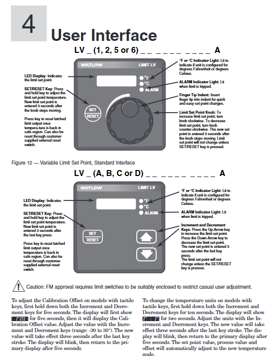
The LV series comes with an operation interface that supports on-site adjustment of 4-digit 7-segment LED display screens (displaying set points), ° F/° C indicator lights, ALARM indicator lights, and adjustable set points through rotary encoders/buttons (supporting on-site modification, with “press setting” to prevent misoperation). Scenes that require frequent adjustment of set points, such as food processing equipment (baking ovens, sterilizers), and small laboratory equipment
LS series safety level design, redundant protection only LED status indicator light (no set point display), fixed set point (customizable at the time of ordering, cannot be modified on site), high safety demand scenarios, such as heating equipment that may cause fires (industrial ovens, painting production lines), medical equipment auxiliary heating protection
2. Core values and differentiation advantages
Independent safety protection: completely independent from the main controller, equipped with sensors, power circuits, and output actuators. Even if the main controller fails (such as sensor failure or output adhesion), it can still reliably trigger protection and avoid the risk of “single point failure”.
Multi installation adaptation: Supports 1/8 DIN panel installation, DIN rail installation, open circuit board installation, and encapsulation module installation, covering various installation needs from standardized cabinets to customized equipment.
Complete authoritative certifications: The entire series has passed UL 873 (temperature regulator), CSA C22.2 # 24 (temperature control), and FM Class 3545 (temperature limit switch) certifications; The LS series additionally complies with UL/EN 60730-1/2-9 (automatic control for household and similar equipment), suitable for harsh scenarios such as food service and medical assistance.
Wide compatibility of sensors: Supports thermocouples (E/J/K/T type) and RTDs (100 Ω platinum resistors), adapting to different temperature ranges and accuracy requirements, such as K-type thermocouples for high-temperature industrial furnaces (-270~1370 ° C) and T-type thermocouples for low-temperature refrigeration equipment (-270~400 ° C).
Product basic specifications
1. Physical and installation specifications
(1) Installation method and size
Installation type size (width x height x depth) Installation requirements Protection level
1/8 DIN panel installation 72.4mm × 72.4mm × 51.7mm (depth behind the panel) panel opening 72.4mm × 72.4mm, thickness 1.52-3.18mm, requires the use of a matching installation bracket to lock the foundation IP20; Optional NEMA 4X/IP65 with buttons (splash proof, dustproof)
DIN rail installation 78.1mm × 112.3mm × 90.7mm (including rail depth 94.7mm) compatible with 35mm × 7.5mm standard DIN rail (DIN 50022), fixed with a snap on structure IP10 (only prevents solid foreign objects)
Installation of an open circuit board with dimensions of 61.7mm × 61.7mm × 45.1mm requires drilling four 3.2mm installation holes, which should be fixed using M2.5 (# 4) screws without protection (to be installed in a closed cabinet)
The installation of the sealing module requires drilling two 5mm installation holes of 70.1mm × 102.9mm × 46.6mm, and fixing them with M3.5 (# 6) screws to IP65 (corrosion-resistant, splash proof, suitable for humid/dusty environments)
(2) Terminal specifications
Terminal type: Two types of terminals can be selected, specify when ordering:
Removable screw terminal: Supports 12-30 AWG wires, with a stripping length of 8mm and a maximum terminal torque of 0.8 Nm (7 in lb) to avoid damage to the terminal due to over tightening.
Wiring identification: Terminal function labels are affixed on the back, clearly indicating terminal definitions such as power supply (L1/L2), sensor (TC+/TC -, RTD S1/S2/S3), output (COM/NO/NC), reset (RESET), etc.
2. Power supply and environmental adaptability
(1) Power supply parameters
Series power supply voltage range, frequency, power consumption, power-off data storage
LF/LV 24V AC(+10%/-15%)、120V AC(+10%/-15%)、230-240V AC(+10%/-15%) 50/60Hz ± 5% maximum 10VA non-volatile memory (parameters not lost)
LS 100-240V AC (+10%/-15%) 50/60Hz ± 5% maximum 10VA non-volatile memory
(2) Environmental parameters
Working environment: Temperature 0-70 ° C (32-158 ° F), relative humidity 0-90% RH (non condensing), avoid direct contact of condensed water with equipment.
Storage environment: Temperature -40-85 ° C (-40-185 ° F), relative humidity 0-95% RH (non condensing).
Anti interference capability: Complies with EN 61326-1 standard, industrial environment anti electromagnetic interference (EMI), sensor cables are recommended to use shielded wires (only grounded at the sensor end), away from high-voltage power lines (spacing ≥ 10cm).
3. Sensor and input specifications
(1) Thermocouple input
Thermocouple Type Range (Example) Accuracy Key Requirements
E-type -200-800 ° C (-328-1470 ° F) ± 1% range ± 1 ° C (standard conditions 25 ° C ± 3 ° C) needs to distinguish between positive and negative poles (red is negative), and extension requires the same type of compensating wire to avoid errors caused by copper wires
J-type 0-750 ° C (32-1382 ° F); LS series: -18-406 ° C (0-763 ° F) ± 1% range ± 1 ° C Suitable for medium and low temperature scenarios, low cost, good oxidation resistance
K-type -270-1370 ° C (-328-2282 ° F); LS series: -18-537 ° C (0-999 ° F) ± 1% range ± 1 ° C Suitable for high temperature scenarios, good stability, widely used in industrial furnaces and kilns
T-type -200-350 ° C (-328-662 ° F) ± 2.4% range (-200-0 ° C), ± 1% range (0-350 ° C) suitable for low temperature scenarios (such as refrigeration equipment), resistant to humidity corrosion
Input impedance:>10M Ω, to avoid errors caused by external circuit shunting; Cold end compensation: Built in electronic cold end compensation with an accuracy of ± 0.1 ° C, without the need for additional compensation wires.
(2) RTD input (only supported by LF/LV)
Type: 100 Ω platinum resistor, in accordance with DIN 0.00385 temperature coefficient curve.
2-wire system: S2 and S3 terminals need to be short circuited. For every 1 Ω increase in wire resistance, the measurement error increases by 2.6 ° C (4.7 ° F). It is recommended that the wire length be ≤ 10 meters.
Excitation current: 125 µ A (nominal), to avoid excessive current causing RTD self heating error.
4. Output and protection specifications
(1) Output type and parameters
Series output types, rated parameters, applicable load life
LF/LV Form C mechanical relay (single pole double throw) 8A/240V AC (resistive load), 250VA (inductive load, 120/240V AC), 30V DC (maximum) contactor coil, solenoid valve, alarm light, etc. Inductive load requires parallel RC suppressor (Watlow P/N 08040147-0000) 100000 cycles (at rated current)
LS Form A mechanical relay (single pole single throw) 8A/240V AC (resistive load), 120VA (inductive load, 120/240V AC) is only used to cut off high-risk loads (such as heating tube power supply), without the need for RC suppressors for 6000 cycles (at rated current)
Output logic: Under normal conditions, the NO (normally open) contact of LF/LV is closed and the NC (normally closed) contact is open; After triggering the restriction condition, the output is locked, the NO contact is disconnected, and the NC contact is closed (cutting off the load power or triggering an alarm).
(2) Protection function
Temperature limit:
High temperature limit (full series): Protection is triggered when the temperature exceeds the set point.
Low temperature limit (LF/LV only): Protection is triggered when the temperature is below the set point (such as freezing of refrigeration equipment).
Sensor fault protection:
Sensor open circuit: triggers output lockout, displays fault code [Er; In] (only LV is displayed).
Sensor short circuit: When the thermocouple is short circuited, the ambient temperature is displayed, and when the RTD is short circuited, the low range value is displayed, both triggering protection.
LS series additional protection:
Dual sensor deviation monitoring: When the temperature difference between the two sensors exceeds 20 ° C, protection is triggered to prevent single sensor failure.
Environmental over temperature protection: When the internal temperature of the controller exceeds 85 ° C, the protection is triggered to avoid self failure.
Reset method:
LF/LV: Supports panel RESET button reset or external momentary normally open switch reset (terminal 9), reset requires temperature to drop below “set point hysteresis”.
LS: Only supports power-off reset (power must be disconnected for ≥ 3 seconds) to prevent accidental operation and release protection, in compliance with safety level design.
Core functions and operation guide
1. Core functional features
(1) Independent security logic
It has no electrical connection with the main controller, independent power supply, independent sampling, and independent output. Even if the main controller loses control (such as output adhesion), it can still monitor the temperature and cut off the load through its own sensors, avoiding “common cause faults”.
Setpoint locking: LF/LS setpoints cannot be modified on site, LV needs to press the SET button to adjust, to prevent unauthorized personnel from operating them incorrectly.
(2) Operation interface functions (LV series only)
The LV series offers two versions of the operating interface, adapted to different operating habits:
Rotary encoder version (Figure 12):
Display screen: 4-digit LED displays the set point, the ° F/° C indicator light displays the current unit, and the ALARM indicator light is on to trigger protection.
Operation: Press the SET/RESET button and rotate the encoder to adjust the set point. After the encoder stops for 3 seconds, it will automatically save; After triggering the protection, press the RESET button to reset (if the temperature meets the standard).
Button version (Figure 13):
Buttons: UP (increase), DOWN (decrease), SET/RESET (confirm/reset). Press the SET button for 3 seconds to enter adjustment mode, UP/DOWN button to modify the set point, no operation saved for 3 seconds.
Advanced function: Press and hold the UP+DOWN button for 5 seconds to enter calibration offset (-30~30 ° C); Press and hold for 10 seconds to switch between ° F/° C units, and the set point and measured value will be automatically converted after switching.
(3) Fault diagnosis and status indication
Solution to the meaning of series fault codes/indicator lights
LV [Er; In] sensor input fault (open/short circuit). Check the sensor wiring and replace the sensor
LS two LED alternate flashing dual sensors temperature difference>20 ° C or polarity reversed check sensor polarity, adjust installation position to ensure temperature difference ≤ 20 ° C
LS Limit LED flashes, Range LED lights up, temperature does not drop to reset threshold, wait for temperature to drop below “set point hysteresis”, or power off to reset
The full range of ALARM LEDs are constantly on, triggering temperature limit protection to investigate the cause of overheating (such as heating tube adhesion), and ensuring temperature safety before resetting
2. Key configuration points
(1) Set point configuration
LF series: The set point is specified by the ordering model, such as “0120” in “LFC4JW0120AAAA” indicating a set point of 120 ° F. It is necessary to ensure that the set point is within the sensor range (such as 0-750 ° C for J-type thermocouples).
LV series: on-site adjustment, the steps are as follows:
Press the SET button for 3 seconds, and the display screen will flash to enter adjustment mode.
Rotary encoder (or press UP/DOWN key) to modify the set point, the range should be within the “low limit set point – high limit set point” (customized when ordering).
Stop the operation for 3 seconds, the display screen stops flashing, and the set point is saved.
LS series: The set point and hysteresis loop are specified by the ordering model, for example, in “LSF4HW0900220AA”, “0900” represents the set point of 900 ° F and “220” represents the hysteresis loop of 20 ° F, which cannot be modified on site.
(2) Temperature unit configuration
LF/LS: Unit specified by ordering model (such as J-type thermocouple with “J” in ° C and “H” in ° F), cannot be switched on site.
LV: The button version supports unit switching, steps:
Press and hold the UP+DOWN key for 10 seconds, and the display screen will show “F” and “C”.
Press the UP key to switch to ° F, and press the DOWN key to switch to ° C.
No operation for 3 seconds, the unit takes effect, and the set point and measured value are automatically converted (such as 100 ° C → 212 ° F).
(3) External reset configuration (LF/LV only)
Wiring: Connect an external momentary normally open switch (such as a button) to terminal 9 (RESET) and the common terminal (COM).
Function: After triggering the protection, press the external switch (or panel RESET button), and if the temperature has dropped to the reset threshold, output a reset; If the temperature does not meet the standard, resetting will be ineffective to avoid danger relief.
Installation and wiring specifications
1. Installation process (taking panel installation and rail installation as examples)
(1) 1/8 DIN panel installation (LV series, IP65 protection)
Preparation for Drilling: Drill holes on the panel in a size of 72.4mm × 72.4mm, with smooth edges and no burrs, and a panel thickness of 1.52-3.18mm.
Sealing gasket inspection: Confirm that the rubber sealing gasket on the front of the controller is not twisted and fits snugly into the groove of the housing to ensure IP65 protection.
Embedded controller: Insert the controller from the front of the panel, with the sealing gasket completely covering the edge of the opening without any offset.
Fixed bracket: Install the bracket from the back of the panel, ensuring that the bracket buckle is aligned with the ridge of the controller housing, press the bracket tightly against the panel, and lock the buckle with your thumb (both side buckles need to be locked at the same time to avoid uneven force causing sealing failure).
Check installation: Gently shake the controller without looseness; The front of the panel has no protrusions/indentations, and the sealing gasket has no compression deformation.
(2) DIN rail installation (LF series)
Rail preparation: Confirm that the DIN rail complies with DIN 50022 standard (35mm × 7.5mm), and is installed on a flat surface inside the cabinet, away from heat sources such as frequency converters and contactors.
Buckle installation: Insert the upper hook of the controller into the upper edge of the guide rail, press the lower part of the controller until the lower buckle “clicks” to lock onto the lower edge of the guide rail (if unable to lock, check if the guide rail is bent, adjust and retry).
Disassembly method: Press the release button on the upper part of the controller, while pulling the lower part forward to disengage the buckle from the guide rail, and remove the controller (disconnect the power and wiring before disassembly).
2. Wiring specifications and safety requirements
(1) Preparation before wiring
Power off confirmation: Before wiring, all relevant power sources must be disconnected, and a multimeter must be used to confirm that there is no voltage to avoid electric shock.
Wire selection:
Power wire: 12-18 AWG copper wire, current carrying capacity ≥ controller maximum current (LF/LV ≤ 0.5A, LS ≤ 0.1A).
Sensor wires: Thermocouples use the same type of compensating wire (such as JX-HS-FF for J-type), RTDs use 3-core shielded wire (20-24 AWG), and the shielding layer is only grounded at the sensor end.
Output wire: Depending on the load current, an additional RC suppressor (Watlow P/N 08040147-0000) needs to be connected in series for inductive loads.
(2) Core wiring example (LF/LV single circuit protection)
Power wiring: L1 (live wire) is connected to terminal 1, L2 (neutral wire) is connected to terminal 2, and a 2A slow melting fuse (250V) is connected in series. The live wire end needs to be connected to a circuit breaker (for easy power-off maintenance).
Sensor wiring (J-type thermocouple): The positive (non red) terminal of the thermocouple is connected to terminal 5, and the negative (red) terminal is connected to terminal 10. The extension wire needs to be a J-type compensating wire to avoid copper wires.
Output wiring: Relay COM terminal is connected to terminal 6, NO terminal is connected to one end of the contactor coil, and the other end of the coil is connected to L2; NC terminal is backup (can be connected to an alarm light), inductive load (contactor coil) is connected in parallel with an RC suppressor (between terminal 6 and NO terminal).
External reset wiring: One end of the external button is connected to terminal 9, and the other end is connected to terminal 6 (COM end). The button is of the instantaneous and constant on type (such as Schneider XB2-BA31).
(3) LS series dual sensor wiring
Power wiring: Connect L1 to terminal 1, L2 to terminal 2, and connect 2A slow melting fuses in series.
Dual sensor wiring (K-type thermocouple): Sensor 1 is connected to positive terminal 5 and negative terminal 10; The positive terminal of sensor 2 is connected to terminal 4, and the negative terminal is connected to terminal 9. The installation positions of the two sensors should be close (temperature difference ≤ 20 ° C).
Output wiring: The relay COM terminal is connected to terminal 6, and the NO terminal is connected to the heating tube power circuit. After triggering the protection, the NO terminal is disconnected, cutting off the heating tube power supply.
(4) Safety wiring requirements
Electrical isolation: Sensor cables, power cables, and output cables need to be wired separately (with a spacing of ≥ 10cm) to avoid electromagnetic interference; The grounding terminal of the controller (if any) needs to be connected to a protective ground (grounding resistance ≤ 4 Ω).
Installation in hazardous areas: Explosion proof junction boxes and armored cables are required for Class 1 Div. 2 hazardous areas, with terminal tightening torque ≥ 0.56 Nm, and live plug and unplug wiring is prohibited.
Anti misoperation wiring: strictly follow the terminal label for wiring, and do not reverse the positive and negative terminals of the power supply or the sensor (otherwise abnormal display or failure to trigger protection).
3. Analysis of Typical System Wiring Diagram (Industrial Oven Protection)
System composition: The main controller (Watlow Series CV) controls the temperature of the oven, while the LF series serves as redundant protection to prevent overheating caused by main controller failure.
Wiring logic:
The LF sensor and the main controller sensor are installed at different positions in the oven to avoid single point failures.
The LF output is connected in series with the main contactor coil circuit, and the main controller output is also connected in series with this circuit, forming a “double safety”.
After triggering the LF protection, the contactor coil loses power, cutting off the power supply to the heating tube, and the ALARM light is on, requiring manual reset (or external button reset).
Troubleshooting and Maintenance
1. Common faults and solutions
Possible causes of malfunction, troubleshooting steps, and solutions
No display/action, ALARM light not on. 1. Power not connected or circuit breaker tripped
2. The fuse is blown
3. The safety interlock switch is not closed (such as the oven door switch). 1. Use a multimeter to measure the voltage at terminal 1/2 and confirm that the power supply is normal
2. Check the fuse of the power circuit. If it is blown, check if there is a short circuit in the load
3. Check the status of the interlock switch to ensure it is closed. 1. Connect the power supply and reset the circuit breaker
2. Replace the 2A slow melting fuse and repair the load short circuit
3. Close the interlock switch (such as closing the oven door)
Abnormal temperature reading (high/low), ALARM light triggered incorrectly. 1. Sensor type configuration error (e.g. actual J type, K type selected when ordering)
2. Reverse the wiring of the sensor
3. Excessive wire resistance (RTD)
4. The ambient temperature exceeds 70 ° C. 1. Check the ordered model and actual sensor type to ensure consistency
2. Swap the positive and negative poles of the sensor and observe if the reading returns to normal
3. Measure the resistance of the RTD wire. If it is greater than 1 Ω, replace the thick wire or shorten the length
4. Measure the temperature inside the cabinet. If it exceeds the temperature limit, add a ventilation fan. 1. If the configuration is incorrect, it needs to be recalibrated at the factory
2. Correct the polarity of the sensor wiring
3. Replace RTD wires with 20 AWG or more
4. Improve cabinet ventilation and reduce ambient temperature
Unable to reset after triggering protection. 1. The temperature has not dropped below the “set point hysteresis”
2. LS series power on reset
3. External reset switch fault: 1. Measure the actual temperature and confirm if it meets the standard (if the set point is 100 ° C and the hysteresis is 3 ° C, it needs to be lowered to below 97 ° C)
2. LS series needs to be disconnected from the power supply for ≥ 3 seconds and then powered on again
3. Measure the reset switch with a multimeter to see if it conducts when pressed. 1. Wait for the temperature to drop to a safe range
2. Perform power-off reset (LS series)
3. Replace the faulty reset switch
Two LEDs flashing alternately (LS series) 1. Dual sensor temperature difference>20 ° C
2. Sensor polarity reversed
3. One of the sensors is faulty. 1. Measure the actual temperature of the two sensors and confirm if the temperature difference exceeds 20 ° C
2. Swap the positive and negative poles of one of the sensors and observe if the flashing stops
3. Short circuit the two sensor terminals separately and observe if they still flash. 1. Adjust the sensor installation position to reduce the temperature difference
2. Correct the polarity of the sensor
3. Replace the faulty sensor
2. Daily maintenance and calibration
(1) Regular maintenance (monthly)
Appearance inspection: The panel is not damaged, the LED indicator light is normal (power light on, ALARM light off), the wiring terminals are not loose or oxidized, and the sealing gasket is not aged.
Functional testing:
Simulate overheating: Heat the sensor with a standard temperature source and confirm that the ALARM light will turn on and output an action when the temperature reaches the set point.
Reset test: After the temperature drops to a safe range, press the RESET button (or power off) to confirm the output reset and ALARM light off.
Cleaning: Wipe the panel with a dry cloth to remove terminal dust. Do not use corrosive cleaning agents such as alcohol and acetone.
(2) Annual calibration
Calibration tools: standard temperature source (such as FLUKE 9170), high-precision multimeter (such as FLUKE 8846A), standard resistance box (for RTD calibration).
Thermocouple calibration steps:
Set the standard temperature source to the midpoint of the sensor range (such as J-type thermocouple 300 ° C), and record the controller display value after stabilization.
If the error is greater than ± 1%, the LV series can adjust the calibration offset through the panel (long press the UP+DOWN button for 5 seconds to enter calibration mode and adjust to the standard value); The LF/LS series needs to be returned to the factory for calibration.
RTD calibration steps:
Use a standard resistance box to output 119.4 Ω (corresponding to 100 ° C, DIN curve), and record the displayed value of the controller.
When the error exceeds the limit, adjust the RTD wire compensation (3-wire system) or return to the factory for calibration.
(3) Fault record
Suggest establishing maintenance logs to record the time, symptoms, troubleshooting process, and solutions of faults, with a focus on recording:
Determine the frequency of sensor failures (such as open circuits and short circuits) and determine whether to replace the sensor or improve the installation environment.
The triggering reasons for over temperature protection, such as frequent adhesion of heating tubes, require early replacement of aging components.
Typical application scenarios
1. Industrial oven temperature protection (LF series)
Requirement: The oven main controller (such as PLC+temperature module) controls heating and requires redundant protection to prevent the main controller output from sticking and causing overheating (such as setting a point of 180 ° C and triggering protection for overheating at 200 ° C).
Configuration: LF series fixed set point of 200 ° C, K-type thermocouple (range 0-300 ° C), potting module installation, output connected in series to the heating tube contactor coil circuit, triggering to cut off the coil power supply.
Advantages: No user interface, preventing unauthorized modifications; The sealing structure is suitable for high temperature environments near the oven and has IP65 protection against dust.
2. Food baking oven protection (LV series)
Requirement: The baking oven needs to adjust the temperature frequently (such as baking bread at 180 ° C and cake at 160 ° C), and the maximum temperature should be limited to 220 ° C to prevent the batter from burning.
Configuration: LV series adjustable set point (range 100-220 ° C), J-type thermocouple, 1/8 DIN panel installation (IP65 protection), rotary encoder to adjust set point, output triggers alarm light and contactor trip.
Advantages: Quick on-site adjustment of set points, with anti misoperation design; IP65 protection is suitable for cleaning and spraying in food processing environments.
3. Heating protection for coating production line (LS series)
Requirement: If the heating tube in the coating and drying section loses control, it may cause a fire and requires high safety level protection. The set point is 120 ° C, dual sensor redundancy, and only power-off reset.
Configuration: LS series double K-type thermocouple, set point 120 ° C, hysteresis loop 5 ° C, DIN rail installation, output directly cuts off the power supply of the heating tube, triggering protection when the temperature difference between the two sensors is greater than 20 ° C.
Advantages: Dual sensor redundancy+power-off reset, in compliance with safety standards; Form A output is only used to cut off high-risk loads and has high reliability.
Specially designed for industrial process control, it can be installed independently or integrated, providing measurement and control of temperature, pressure and other parameters, supporting single/multi loop linkage, adapting to bidirectional control scenarios such as heating and cooling, and possessing both basic control and advanced extended functions (such as cascade control and proportional control).
2. Basic specifications
Appearance and Installation: 96 × 96mm panel installation, thickness 97mm, with reserved panel openings of 92-93mm, vertical installation, supporting NEMA 4X/IP65 protection level (must be properly tightened and sealed).
Power supply requirements: 100-240V AC (50/60Hz) or 24-28V AC/DC, maximum power consumption of 39VA, Class 2/SELV certified power supply, supporting Semi F47-0200 voltage drop standard.
Environmental adaptability: working temperature 0-65 ° C, storage temperature -40-70 ° C, 0-90% RH (non condensing), compliant with UL, CE, EN 61010 and other safety certifications, some models support Class 1 Div. 2 hazardous areas.
Warranty and Support: 3-year warranty (non misuse scenario), technical support can be obtained through phone or email, and returns need to apply for an RMA number in advance.
Universal analog input 1 channel (advanced version 2-3 channels) supports thermocouple (11 types including J/K/T), RTD (2-3 wire system, 100 Ω platinum), process signal (0-10V, 4-20mA, etc.), input impedance: voltage 20k Ω, current 100 Ω, temperature, pressure and other parameter acquisition
Four digital inputs support dry contact/DC voltage input (low state<2V, high state>3V), with a response frequency of 10Hz for external triggering and status feedback (such as door switches and limit signals)
(2) Output type and specifications
Output Type Quantity Key Parameters Applicable Scenarios
Control output 2-channel (1A/1B) optional relays (2A/250V AC), SSR (0.5A/24-253V AC), open collector (42V DC/0.5A), process output (4-20mA/0-10V) to drive heaters, refrigeration equipment, valves
Resend output (optional) 1-2 channels of 4-20mA (maximum 800 Ω) or 0-10V (minimum 1k Ω) with an accuracy of ± 30 μ A/± 15mV signal to the recorder PLC
2. Control and calculation functions
(1) Basic control mode
Switch control: The device can be started and stopped by setting a threshold and hysteresis, and the hysteresis can be adjusted (1-9999 units) to avoid frequent switching.
PID control: supports proportional (P), proportional integral (PI), and proportional integral derivative (PID) regulation, stores 5 sets of PID parameters, and adapts to different operating conditions for switching.
Automatic tuning: Through 4 oscillation tests crossing the set point, the optimal PID parameters are automatically calculated, supporting local (internal loop) or global tuning.
Multi PID switching: can trigger 5 sets of PID parameter switching based on set points or process values, suitable for a wide range of operating conditions (such as different characteristics in high and low temperature ranges).
(2) Advanced control functions
Cascade Control (Advanced Version): Dual loop linkage, with the output of the external loop (such as process temperature) serving as the set point for the internal loop (such as heat source temperature), reducing overshoot and hysteresis.
Proportional/Differential Control (Advanced Version): Proportional control supports proportional operation between process values and reference values, while differential control adjusts output based on parameter change rate.
Valve positioning control (advanced version): Feedback valve position through potentiometer, dual output control valve switch, support dead zone and hysteresis adjustment, compatible with three-way valves.
Slope control: Set the rate of temperature/parameter change (1-999 units/minute/hour) to avoid process fluctuations caused by rapid changes.
3. Alarm and safety functions
Alarm types: Support process alarm (fixed threshold), deviation alarm (relative to the set point), rate alarm (parameter changes too quickly), with 2 independent alarm outputs.
Alarm configuration: High and low alarm thresholds, hysteresis (1-9999 units), lockout/automatic reset, and startup mute can be set to avoid false alarms during the startup phase.
Fault protection: supports sensor open circuit detection, automatically switches to manual mode (output 0%) after triggering, and displays fault codes; Optional independent limit controller linkage to prevent overheating/overpressure risks.
4. Communication and Expansion
Communication protocol: Supports EIA-232/EIA-485 bus, Modbus RTU protocol, baud rate 9600/19200/38400bps, addresses 1-247, maximum transmission distance 1200 meters (EIA-485).
Scalability: The advanced version supports 2-3 analog inputs, remote set point inputs, dual loop cascading, and can trigger set point switching, mode switching, and other functions through digital inputs.
Operation and Configuration Guide
1. Menu and Navigation
Core page: divided into 4 levels of pages – homepage (status display), operation page (PID tuning, alarm setting), configuration page (input/output, system parameters), factory page (calibration, safety settings).
Operation mode: 4 directional keys (up and down adjustment/left and right navigation)+automatic/manual switch key+information key (parameter description), supports guided configuration, intuitive operation logic.
Display function: 5-segment red LED main display (process value)+green LCD auxiliary display (status, menu), supporting 16 custom status display items (such as output power, PID group).
2. Key configuration process
(1) Basic configuration steps
System configuration: Select temperature units (° F/° C), PID unit system (SI/Imperial), and power failure response mode.
Input configuration: Select sensor type, range, filtering time (0-60 seconds), linearization compensation (10 point calibration).
Output configuration: Set the control output type (heating/cooling), cycle (0.1-60 seconds), and process output range (e.g. 4-20mA corresponds to 0-100%).
Alarm configuration: Select the alarm type, threshold, and linkage output logic (normally open/normally closed).
PID tuning: Start automatic tuning or manually adjust the proportional band, integration time, and differentiation time.
(2) Advanced configuration
Cascade control: Configure the range and PID parameters of the external loop (process parameters) and internal loop (heat source parameters), and the set point of the internal loop is determined by the output of the external loop.
Remote Setpoints: Switch 3 sets of remote setpoints through analog input (such as 4-20mA) or digital input, suitable for multiple process scenarios.
Security settings: 4-level permission control (full access/read-only/password protection/hidden), supporting 4-digit password setting and modification to prevent unauthorized operations.
3. Calibration and maintenance
Input calibration: for thermocouples RTD、 Process signals can be calibrated using standard signal sources (such as 0-10V, 4-20mA) for two-point/multi-point calibration, supporting the restoration of factory calibration values.
Output calibration: Adjust the accuracy of control output and retransmission output to ensure that the signal is consistent with the set value (e.g. 4mA corresponds to 0%, 20mA corresponds to 100%).
Self diagnosis: supports hardware fault detection (such as RAM and Flash faults), module recognition, parameter verification, and intuitive display of fault codes.
Installation and Wiring Guide
1. Installation process
Panel drilling: Drill holes according to the size of 92-93mm, clean the installation surface, and ensure that there are no oil stains or burrs.
Controller fixing: Insert the controller into the panel, install the fixing bracket and sealing gasket, and tighten the screws (NEMA 4X protection requires ensuring that the sealing gasket is compressed evenly with a gap of ≤ 0.508mm).
Wiring specifications: Sensor cables and power cables should be wired separately (with a spacing of ≥ 10cm), and shielded twisted pair cables should be used for analog signals. The shielding layer should be grounded at one end (on the control room side).
2. Wiring requirements
(1) Core terminal definition
Power terminal: 100-240V AC connected to L/N, 24V DC connected to+/-, requires series connection of slow melting fuses (2A/250V).
Analog input terminals: thermocouple connected+/-, RTD (3-wire system) connected S1/S2/S3, process signal (4-20mA) connected+/- (requires external power supply or loop power supply).
Control output terminals: Relay output connected to COM/NO/NC, SSR output connected to control terminal, process output connected to signal+/-.
Communication terminals: EIA-485 is connected to T+/T -/GND, EIA-232 is connected to TX/RX/GND, and supports daisy chain topology (with 120 Ω terminal resistors connected at the beginning and end).
(2) Safe wiring
Installation in hazardous areas: Explosion proof junction boxes and armored cables are required for Class 1 Div. 2 models, and live plug and unplug wiring is prohibited.
Inductive load protection: When driving relays and solenoid valves, parallel RC suppressors (Watlow 0804-0147-0000) or freewheeling diodes are required to prevent voltage spikes from damaging the module.
Electrical isolation: Input, output, and communication circuits are isolated from each other to avoid grounding loops (grounding resistance ≤ 4 Ω).
3. Typical application wiring
Single loop temperature control: thermocouple/RTD connected to analog input, control output to drive heater, alarm output linked to buzzer/indicator light, communication interface connected to PLC for remote monitoring.
Cascade control system: The external loop (process temperature) input is connected to a temperature sensor, and the output controls the set point of the internal loop (heat source). The internal loop input is connected to a heat source temperature sensor, and the output drives the heating equipment.
Troubleshooting and Maintenance
1. Common faults and solutions
Possible causes and solutions for the fault phenomenon
No display/power light not on, abnormal power supply, blown fuse, reversed wiring. Measure the power supply voltage, replace the 2A slow melting fuse, and check the positive and negative wiring
Abnormal sensor reading, incorrect sensor type configuration, loose wiring, shielding interference. Check the sensor model and configuration, re tighten the wiring, and check the grounding of the shielding layer
Communication failure: baud rate/address mismatch, reversed wiring, terminal resistance not connected. Unified communication parameters, correct T+/T – polarity, and add 120 Ω resistors to the first and last modules
Alarm does not trigger threshold setting error, alarm function is not enabled, hysteresis is too large, reset alarm threshold, enable alarm output, reduce hysteresis (such as changing from 5 ℃ to 1 ℃)
Regular inspection: Check the terminal fastening, wiring integrity, display screen status every month, and remove panel dust (avoid using corrosive cleaning agents).
Calibration cycle: It is recommended to calibrate the input and output accuracy once a year, and for scenarios with large process fluctuations, it can be shortened to 6 months.
Parameter backup: configure parameters through software backup to avoid reconfiguration after failure; Record key parameters (such as PID group, alarm threshold) for easy maintenance.
Typical application scenarios
Industrial furnace temperature control: Collecting furnace temperature through thermocouples, adjusting heating power through PID, linking alarm output to prevent overheating, and implementing slope control to achieve slow heating and avoid workpiece deformation.
Refrigeration system control: Dual output controls the compressor (refrigeration) and heater (insulation) separately, deviation alarm monitors temperature fluctuations, and cascade control adapts to the temperature linkage of the condenser and evaporator.
Chemical pressure control: Process input is connected to a pressure sensor (4-20mA), proportional control is used to adjust valve opening, rate alarm is used to prevent pressure fluctuations, and remote set points support multi process pressure switching.
Valve positioning control: feedback valve position through potentiometer, dual output control valve switch, dead zone adjustment to avoid frequent actions, suitable for precise fluid flow control.
As the I/O expansion core of the RM system, it does not have independent PID control function and focuses on supplementing digital/analog I/O interfaces, providing logical operations, timing and counting, special equipment control (compressor/valve/sequencer) and other functions. It can be networked with RM series modules such as RMC (controller) and RMA (communication gateway), and supports up to 17 modules (1 RMA+16 other RM modules) to work together.
Power supply requirements: 20.4-30.8V AC/DC, Class 2 or SELV certified power supply, power consumption 7W/14VA, supporting Semi F47-0200 voltage drop standard.
Environmental adaptability: Operating temperature -18~65 ° C, storage temperature -40~85 ° C, 0-90% RH (non condensing), protection level IP20, required to be installed in NEMA Type 1 or above protective enclosures.
Certification standards: UL/EN 61010, Class 1 Div. 2 (optional) RoHS、WEEE、CE, Some models have passed FM Class 3545 certification.
Warranty and Support: 3-year warranty (non misuse scenario), technical support can be obtained through phone, email or local representative, and RMA number needs to be applied for in advance for returns.
Core functions and technical features
1. I/O expansion function
(1) Input type and specifications
Digital input: up to 24 channels, supporting dry contact/DC voltage input (low state<2V, high state>3V), dry contact closing resistance<50 Ω, open circuit resistance>100K Ω.
Current Transformer (CT) Input: Up to 16 channels, input range 0-50mA AC, compatible with 16-0246 CT models, accuracy ± 1mA, response time ≤ 1 second.
(2) Output type and specifications
Applicable scenarios for key parameters of output types
Digital output (open collector) maximum 32V DC, single channel 1.5A, total sink current 8A, small relay drive, sensor power supply
Mechanical relay 5A/240V AC, Form A contact, 100000 cycle life, high-power equipment switch control
Solid state relay (SSR) 2A/20-264V AC (4 channels) or 10A/240V AC (2 channels) high-frequency switch load (heater, motor)
Process/retransmission output 0-10V DC (minimum 4k Ω load) or 0-20mA DC (maximum 400 Ω load) signal retransmission, valve positioner control
2. Control and calculation functions
(1) Basic control module
Logical operation: 16 logical instances, supporting 8 logical relationships such as AND/OR/NOT/XOR, and can access up to 8 input sources.
Timing function: 8 timer instances, supporting pulse/delay/single trigger/hold timing, with a time range of 0-9999 seconds.
Counting function: 8 counter instances, supporting increasing and decreasing counting, load value setting, target value triggering output, counting range 0-9999.
Mathematical operations: 8 mathematical examples, supporting 16 operations such as addition, subtraction, multiplication, division, mean, maximum/minimum, square root, etc., and supporting multiple input source combinations.
Linearization: 8 linearization instances, 10 point linearization calibration, suitable for non-standard sensor signal correction.
(2) Special equipment control
Compressor control: Supports linkage of 1-2 control circuits, with adjustable start stop thresholds and minimum start stop times to avoid frequent start stop wear.
Electric valve control: supports valve fully open/fully closed control, configurable travel time and dead zone, suitable for two-wire valve drive.
Sequencer control: distributes a single power signal into 4 outputs, supports linear/cyclic output sequence, and balances load wear.
3. Communication and Networking
(1) Support agreement
Standard configuration: Watlow Standard Bus (EIA-485), used for inter module communication, supports 17 nodes.
Extension Protocol: Supports industrial buses such as EtherNet/IP, DeviceNet, PROFIBUS DP, etc. through RMA module.
(2) Networking standards
Topology: EIA-485 adopts a daisy chain topology, with 120 Ω terminal resistors connected at the beginning and end.
Distance limit: EIA-485 maximum 1200 meters (shielded twisted pair), EIA-232 maximum 15 meters.
Anti interference: Communication lines and power lines should be wired separately (with a spacing of ≥ 10cm), using shielded twisted pair cables, and the shielding layer should be grounded at one end.
4. Alarm and safety functions
Alarm function: 8 alarm instances, supporting process alarm/deviation alarm, configurable high and low alarm points, hysteresis, and locking/non locking modes.
Safety features: Class 1 Div. 2 models support use in hazardous areas (temperature code T4), require the use of certified components, and prohibit live plugging and unplugging of wiring.
Permission management: Supports user/administrator two-level passwords, with optional rolling passwords (automatically changed after power failure) to prevent unauthorized operations.
Installation and Wiring Guide
1. Installation process
Rail installation: The hook is fixed to the 35mm rail and the rotating buckle is locked; When splicing multiple modules horizontally, ensure that the backplane bus is fully in contact.
Rail installation: Connect two rails through Inter module Bus, with a maximum distance of 200 feet, and require independent power supply to avoid voltage drop. The communication line uses shielded twisted pair.
2. Wiring specifications
(1) Core terminal definition
Power terminal (Slot C, 98/99): 98+, 99-, AC/DC polarity should be distinguished and reverse connection is prohibited.
Communication terminal (Slot C): CF (common terminal) CD(T-/R-)、CE(T+/R+), Used for Standard Bus/Modbus RTU communication.
I/O terminals (Slot A/B/D/E): Configure corresponding digital I/O, relay output, and process output terminals according to the model, and refer to the terminal table corresponding to the model for detailed definition.
(2) Wiring requirements
Wire specifications: Supports 12-30 AWG single/multi strand copper wire, with a stripping length of 7.6mm and a terminal torque of 0.56 Nm (right angle terminal)/0.5 Nm (front terminal).
Electrical isolation: Digital I/O and process outputs need to be electrically isolated from power lines to prevent grounding loops (grounding resistance ≤ 4 Ω).
Inductive load: When driving inductive loads such as relay coils and solenoid valves, RC suppressors or freewheeling diodes need to be connected in series.
3. Typical networking examples
Single rail I/O expansion: 1 RMA (communication gateway)+1 RMC (controller)+2 RME (expansion), RME provides digital I/O access to sensors/actuators, and communicates with RMC through Standard Bus.
Track based distributed control: Two rails are deployed with RME modules respectively, connected through Inter module Bus, sharing control logic and reducing on-site wiring length.
Operation and Configuration Guide
1. Menu and Operation
Configure through RUI (Remote User Interface) or EZ-ZONE Configurator software, with three levels of menus:
Operations page: View I/O status, alarm status, timing/counting results, etc.
Setup page: Configure core parameters such as I/O direction, logical relationships, timing parameters, alarm thresholds, etc.
Connection method: Connect the module’s Standard Bus terminal through a USB-EIA-485 converter, and the software will automatically scan the RM module in the network.
Core configuration: It can configure I/O functions, logical operation relationships, communication parameters, alarm rules, etc., and supports configuration file backup and batch import.
Maintenance and troubleshooting
1. Daily maintenance
Regular inspection: Check the terminal fastening, wiring integrity, and module indicator light status (Power/Comm light is normally green) every month.
Cleaning and maintenance: Wipe the shell with a dry cloth to avoid corrosive cleaning agents; SD card (if available) regularly backs up data to prevent full storage.
Spare parts management: Class 1 Div. 2 models require the use of original factory certified spare parts, and it is prohibited to replace components arbitrarily.
2. Common faults and solutions
Possible causes and solutions for the fault phenomenon
Communication failure address/baud rate mismatch, wiring error, terminal resistance not connected. Check communication parameters, check EIA-485 polarity, and connect 120 Ω resistors to the front and rear modules
Abnormal counting/timing trigger signal not connected, incorrect trigger level setting, check trigger signal wiring, adjust trigger level (high/low state)
Typical application scenarios
Industrial equipment I/O expansion: Supplement digital I/O to RMC controllers, connect temperature sensors, limit switches, solenoid valves and other devices, and achieve multi device linkage control.
Distributed control networking: In the track configuration, RME is deployed on site, connected to nearby device I/O, and communicates with the control room controller through the bus to reduce wiring costs.
Special equipment control: achieve stable operation of the refrigeration system through compressor control function, or adjust fluid flow through electric valve control, suitable for HVAC, chemical and other scenarios.
Logic and timing control: Equipment interlocking (such as pump and valve linkage) is achieved through logical operations, and delayed start stop is achieved through timing function, which is suitable for production line process control.