TOSHIBA Commercial Split Variable Frequency Air Conditioning (DI) Series
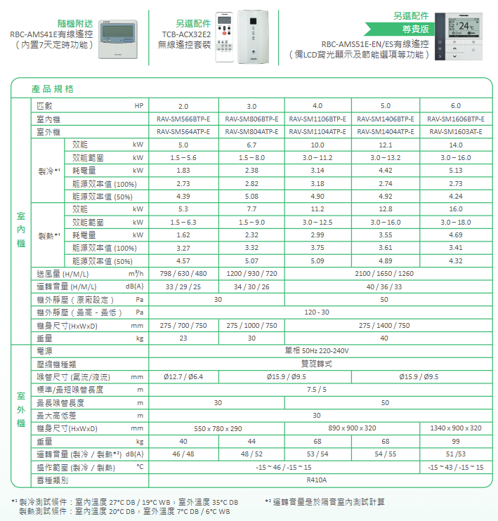
Toshiba Commercial Split Frequency Conversion (DI) series air conditioners, covering multiple specifications of 2.0-6.0 horsepower, offer models such as concealed ceiling card type, floor type, and duct type. The core advantage is the integration of PAM+PWM hybrid frequency conversion technology to achieve fast temperature control and energy saving. Equipped with Aqua Resin coating to ensure clean air, R410A environmentally friendly snow type is used, and the body is light, small, and easy to install (4-5 horsepower models reduce 8kg weight). The operating temperature range is wide (cooling -15 ℃ to 46 ℃, heating -15 ℃ to 15 ℃), equipped with multiple types of remote controls, which are environmentally friendly, efficient, and durable, suitable for various commercial scenarios.
Model and model:
Model type, horsepower range, indoor unit model example, outdoor unit model example
Hidden ceiling card 2.0-6.0 horsepower RAV-SM564UTP-E (2.0 horsepower), RAV-SM1604UTP-E (6.0 horsepower), RAV-SM564ATP-E (2.0 horsepower), RAV-SM1603AT-E (6.0 horsepower)
Bottom mounted 2.0-6.0 horsepower RAV-SM566BTP-E (2.0 horsepower), RAV-SM1606BTP-E (6.0 horsepower) concealed ceiling card outdoor unit
Duct type 2.0-6.0 horsepower RAV-SM568CTP-E (2.0 horsepower), RAV-SM1608CTP-E (6.0 horsepower) concealed ceiling card outdoor unit
Core Technologies and Advantages
Hybrid frequency conversion system (PAM+PWM):
Working principle: First, use PAM technology to run at full capacity and quickly lower the room temperature to the target value; Further precise control through PWM technology to maintain temperature stability
Core value: Balancing rapid temperature control and energy conservation, reducing energy consumption
Aqua Resin coating technology:
Application location: indoor unit evaporator fins
Function and effect: prevent moisture and oil from adhering, reduce the accumulation of dust, bacteria, and allergens, and continuously output clean air
Environmental and energy-saving characteristics:
Snow type: R410A environmentally friendly snow type is used, which does not damage the ozone layer and has a small impact on the environment
Energy Efficiency: The EER value can reach up to 3.31 at 100% load and 5.49 at 50% load, ranking among the top in the industry
Installation and adaptation advantages:
Body design: The outdoor unit is compact in size, with a 4-5 horsepower model that is 8kg lighter than the old model. It supports double-layer wall mounting, saving installation space
Temperature adaptation: Cooling operating temperature range -15 ℃ to 46 ℃, heating operating temperature range -15 ℃ to 15 ℃, can also be used normally in low-temperature areas
Easy operation and maintenance:
Outdoor unit configuration: equipped with a detection window, 2 touch sensitive maintenance switches, 6LED maintenance reminder light, convenient for finding switches, and reducing the risk of electric shock
Air supply control: Some models support independent fan blade control, including three modes of standard up and down swing, diagonal swing, and multi angle turning swing, for more uniform air supply
Key Performance Parameters (Summary Table)
Performance category core parameter numerical range (2.0-6.0 horsepower)
Refrigeration efficiency rated efficiency 5.0-14.0 kW
Efficiency range 1.5-16.0 kW
Rated power consumption 1.56-4.49 kW
Energy efficiency value (100% load) 2.80-3.31
Energy efficiency value (50% load) 4.86-5.49
Heating efficiency rated efficiency 5.3-16.0 kW
Efficiency range 1.5-18.0 kW
Rated power consumption 1.36-4.43 kW
Energy efficiency value (100% load) 3.61-3.90
Energy efficiency value (50% load) 4.91-5.50
Supply air and noise supply air volume (H/M/L gear) 540-2130 m ³/h
Indoor unit operating noise 25-46 dB (A)
Outdoor unit operating noise (cooling/heating) 46-55 dB (A)/48-55 dB (A)
Hardware specifications: Power supply single-phase 50Hz 220-240V
Compressor type: Double rotating type
Throat size (airflow/liquid flow) Ø 12.7/Ø 6.4 mm or Ø 15.9/Ø 9.5 mm
Throat length (maximum) 30-50 m
Maximum height difference of 30 meters
Indoor unit weight 20-40 kg
Outdoor unit weight 40-99 kg
Remote control configuration and optional accessories
Standard remote control:
Hidden ceiling card: wireless remote control (model RBC-U31PGP (W) – E)
Bottom type: Wireless remote control kit (model RBC-CX33CE1)
Duct type: wired remote control (model RBC-AMS41E, built-in 7-day timer function)
Optional accessories:
RBC-AMS41E wired remote control: built-in 7-day timer function (standard on some models, optional on others)
RBC-AMS55EN/ES wired remote control (premium version): with LCD backlight display, energy-saving options and other functions
TCB-ACX32E2 wireless remote control kit (duct type optional)