YOKOGAWA CENTUM VP System (Vnet/IP Version)
Core components and software packages of the system
1. Core components (hardware)
Component Type Core Device Function Description
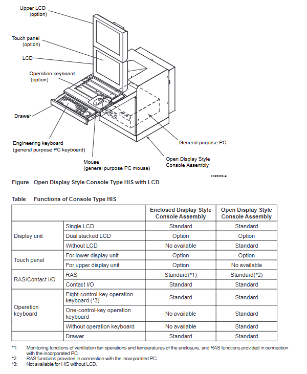
Operation monitoring HIS (Human Interface Station) human-machine interaction interface, supports desktop/console type, can integrate engineering functions
Engineering Station (ENG) system configuration and maintenance, supporting integration and deployment with HIS
Control class FCS (Field Control Station) core control computing unit, FCU model includes AFV10 /AFV30 /AFV40 (single/dual redundancy)
Advanced Process Control Station (APCS) for extended control and computation, improving factory operational efficiency
Gateway class GSGW/USGS/BIOS subsystem integrated gateway, supporting Modbus, OPC and other protocols
Network equipment L2SW/L3SW layer 2/3 switches, intra/inter domain communication relays (1Gbps rate)
The routing devices V net router and WAC router connect Vnet/IP to V net domain and wide area network (WAN) communication
2. Classification of core software packages
Software type represents model core function
Standard operation and monitoring functions of LHS 110 operation monitoring software
Operation monitoring software LHS1150 remote operation and monitoring server function
Operation monitoring software LHS4000 million tag processing (up to 1 million tags/system)
LHS5100 Standard Builder Function for Engineering Software (System Configuration)
Engineering software LHS5150 graphic builder (controls drawing creation)
Compliance software LHS5170 FDA 21 CFR Part 11 adaptation (access control, audit trail)
Extended function software LHS6530 report generation function
Extended Function Software LHS4450 Multi Project Connection Function (Hierarchical/Bidirectional Connection)
Network architecture and communication specifications
1. Core network (Vnet/IP)
Network attribute: Dual redundant control network based on Gigabit Ethernet (Bus1/Bus2), automatically switches in case of control communication failure
Topology structure: star topology
Communication speed: 1Gbps (between L2SW/L3SW), 100Mbps (between device and L2SW)
Transmission medium: Category 5e and above unshielded twisted pair (UTP), RJ-45 interface
Transmission distance: maximum 100m between device and L2SW; maximum 5km between L2SW (1000BASE-LX)
System size limitation:
Up to 64 Vnet/IP devices per domain
Up to 16 domains and 256 sites per system
2. Auxiliary network (Ethernet)
Purpose: File transfer, HIS/ENG communication
Protocol basis: IEEE802.3
Special configuration: When certain conditions are met, Vnet/IP Bus2 can be reused, with a communication bandwidth not exceeding 300Mbps
3. I/O communication bus (Class 3 core bus)
Bus type adaptation FCU transmission rate transmission medium maximum distance connection node limit
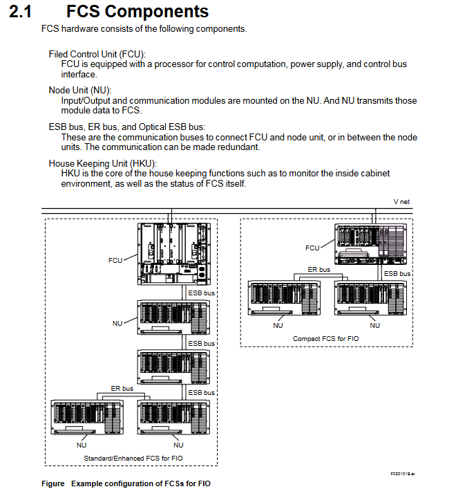
ESB bus AFV10 /AFV30 /AFv40 128Mbps dedicated cable (YCB301) 10m AFV10 up to 9; AFV30 /AFV40 up to 13
Optical ESB bus AFV30 /AFV40 128Mbps single-mode fiber (LC interface) 50km (relay module) same as ESB bus
ER bus AFV10 10Mbps coaxial cable (YCB141/YCB311) 185m (YCB141) maximum 14 per FCU, maximum 8 per bus
System configuration and expansion
1. System size limitation
Remarks on configuration item limit values
The maximum number of operation monitoring tags is 1 million/LHS4000 package needs to be enabled for the system, with a default maximum of 100000
The minimum system configuration of HIS x 1+ENG x 1+FCS x 1 HIS and ENG can be merged into one computer
Maximum number of FCS 114/system single FCS default 200 control drawings, maximum 500
Multi project connectivity supports hierarchical/bidirectional connectivity. Bidirectional connectivity is only applicable to CENTUM VP/CS 3000 projects
2. System expansion methods
Inter domain extension: Connect multiple Vnet/IP domains through L3SW, supporting up to 16 domains
Cross network expansion: Connect Vnet/IP and V net domains through V net routers, supporting a 3-layer hierarchical structure
Wide Area Expansion: Connect to WAN (including satellite communication) through WAC router to achieve remote device monitoring
Multi project extension: Implementing integrated monitoring of multiple projects through LHS4450 package (hierarchical/bidirectional mode)
Compliance and installation environment
1. Core compliance standards
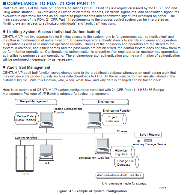
FDA 21 CFR Part 11: Supports electronic record/signature, access control, and audit trail functionality
Safety standards: CSA C22.2 No.61010-1, CE Low Voltage Directive EAC CU TR 004
EMC standards: EN 55011 Class A, RCM, KC Marking
Explosion proof standards: CSA Non Intrinsic, FM Non Intrinsic, Type n/i (intrinsic safety)
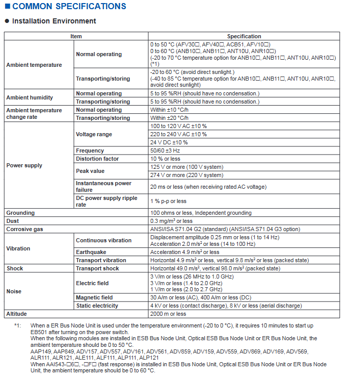
2. Installation environment requirements
Environmental Parameters Desktop Equipment (HIS/ENG) Control Equipment (FCS/Node Unit)
Working temperature 5-40 ℃ 0-50 ℃
Relative humidity 20-80% RH 10-90% RH (non condensing)
Temperature change rate ± 10 ℃/hour ± 10 ℃/hour
Power supply voltage 100-120V AC ± 10%, 220-240V AC ± 10%, 24V DC ± 10%, same as left
Grounding requirement: independent grounding, resistance ≤ 100 Ω, independent grounding, resistance ≤ 100 Ω
Vibration requirements 1-14Hz (0.25mm amplitude), 14-100Hz (2m/s ²) are the same as the left
Integration of related systems
ProSafe RS: Safety Instrumented System (SIL 3 certified), can be integrated with CENTUM VP, and monitors SCS through HIS
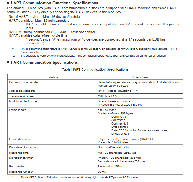
PRM (Plant Resource Manager): Equipment Asset Management System, supporting equipment monitoring such as HART, FOUNDATION fieldbus, etc
Third party system: Third party PLC/PCS integration supporting Modbus, EtherNet/IP, OPC and other protocols through UGS/BIOS

Key issues
Question 1: What are the core advantages of the network architecture of the CENTUM VP system (Vnet/IP version)? What is the functional division between Vnet/IP and I/O communication bus (ESB/optical ESB/ER)?
answer
Core advantages of network architecture:
Dual redundancy design: The Vnet/IP control network adopts Bus1/Bus2 dual redundancy, which automatically switches in case of failure to ensure uninterrupted control communication;
High speed transmission: The communication speed within/between domains reaches 1Gbps, meeting real-time control requirements;
Strong scalability: Supports 16 domains/systems, 256 sites/systems, and achieves cross domain/wide area expansion through L3SW and routers.
Functional division of labor:
Vnet/IP: The system core control network is responsible for real-time control data and management information transmission between HIS, ENG, FCS and other sites;
ESB bus: I/O communication between FCS and local node units, with a speed of 128Mbps and a maximum transmission distance of 10m, compatible with the full range of AFV FCUs;
Optical ESB bus: Long distance I/O communication, based on single-mode fiber, with a maximum transmission distance of 50km, only compatible with AFV30 /AFV40 ;
ER bus: AFV10 Exclusive remote I/O communication, 10Mbps speed, maximum transmission distance of 185m, supports 4 buses/FCU.
Question 2: How does the CENTUM VP system meet FDA 21 CFR Part 11 compliance requirements? What are the key limitations to consider when expanding the system scale?
answer
FDA 21 CFR Part 11 Compliance Implementation:
Access control: Supports engineer/operator identity authentication, requires prior registration of username and password, and cannot operate without legal permission;
Permission confirmation: Independently verify whether the operator has specific operational permissions;
Audit tracking: Record engineering operations that affect product quality (such as FCS data downloads), including the operator, time, content, reason for changes, and traceability;
Data storage: Audit tracking data is stored on dedicated servers that support archiving and retrieval.
Key limitations of scale expansion:
Number of tags: default maximum of 100000 per system, maximum of 1 million after enabling LHS4000 package;
Domain and site: up to 16 domains/systems, 256 sites/systems, with a maximum of 64 Vnet/IP devices per domain;
FCS quantity: A maximum of 114 FCS per system, including up to 86 AFV30/AFV40 and up to 64 AFV10;
Control drawing: By default, a single FCS has 200 control drawings, but with the LFS1750 package enabled, the maximum is 500.
Question 3: What is the functional positioning of the core components (HIS/ENG/FCS) of the CENTUM VP system? What are the modes of multi project connection and what are the applicable scenarios?
answer
Functional positioning of core components:
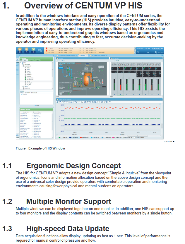
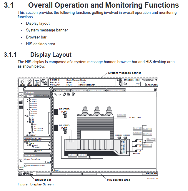
HIS (Human Machine Interface Station): The operation and monitoring core provides functions such as graphical views, trend analysis, alarm management, etc. It supports desktop/console types and can integrate engineering functions;
ENG (Engineering Station): System configuration and maintenance, control logic design and equipment configuration are implemented through software packages such as LHS5100, which can be combined and deployed with HIS;
FCS (Field Control Station): controls the computing core, performs functional block operations, and I/O data exchange. The FCU supports single/dual redundancy to ensure control reliability.
Multi project connection mode and applicable scenarios:
Hierarchical Connection: The upper level CENTUM VP project monitors the lower level projects (supporting VP/CS 3000/CS 1000/CS), and only the upper level requires the installation of LHS4450 package, which is suitable for centralized monitoring of multi-level factories;
Bidirectional connection: The connected project can be monitored in both directions and is only applicable between CENTUM VPs or between VP and CS 3000. Both parties need to install LHS4450 package, which is suitable for multi factory collaborative control scenarios.