SIEMENS SIMATIC S5 S5-115U Programmable Controller
SIMATIC S5-115U is a programmable controller suitable for the mid to low end performance range. It adopts a modular design, with core components including power module, CPU (941/942/943/944 models), I/O module, etc. It supports both centralized and distributed configurations, and can expand up to 3 expansion units. In terms of communication, it is compatible with various systems such as SINEC L1. Programming relies on STEP 5 language and has functions such as interrupt handling and analog processing. It is suitable for multiple industries such as automotive, chemical, and food. Installation needs to follow mechanical fixation, standardized wiring, and electromagnetic compatibility requirements. Startup and testing need to complete steps such as overall reset, program transmission, parameter setting, and fault diagnosis.
Core hardware components
2.1 Power module (PS 951)
Input voltage: 120V AC, 230V AC, or 24V DC
Output current: 3A, 7A, 15A (7A and below do not require a fan)
Backup function: Lithium battery backup program memory and retention flag/timer/counter, battery life of about 2 years
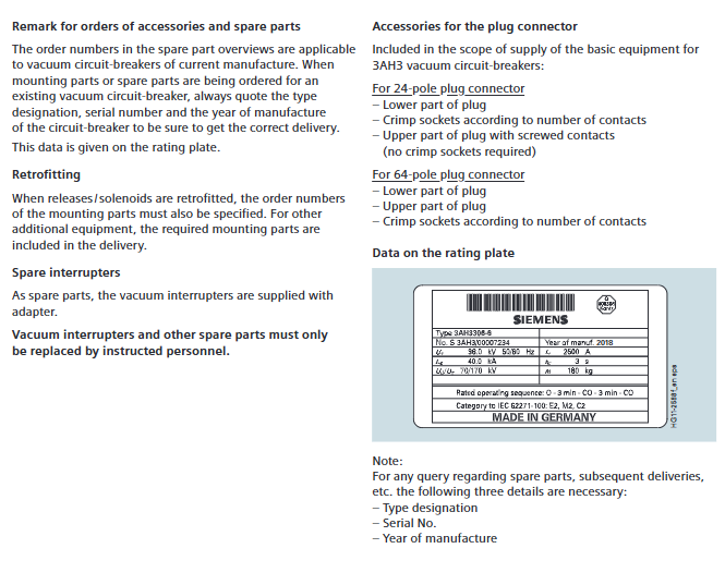
Key features: Equipped with battery failure LED indicator, reset switch, voltage selection switch
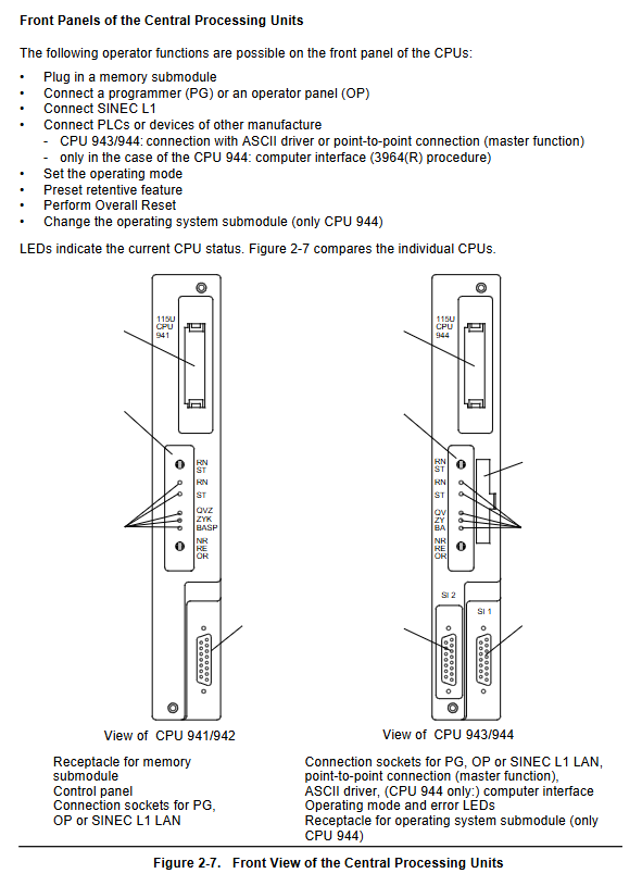
2.2 CPU module
CPU model, memory capacity, execution time (in thousands of instructions), core features
CPU 941 internal 2Kbytes, maximum 18Kbytes, approximately 10ms basic type, supports PID control
CPU 942 internal 10Kbytes, maximum 42Kbytes, approximately 10ms enhanced, supports PID control
CPU 943 internal 48Kbytes approximately 5ms dual serial ports, including real-time clock and ASCII driver
CPU 944 internal 96Kbytes, approximately 1.5ms dual serial port, supports 3964/3964R protocol, PID control
Common features: Supports 1024 flag bits, 128 timers/counters, time range 0.01-9990s, counting range 0-999
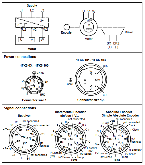
2.3 I/O modules
Digital module: adapted to machine voltage/current levels, supports screw or crimping connections
Simulation module: handles closed-loop control tasks, up to 4 measurement ranges per module, supports range card replacement
Intelligent I/O module: independent processor, parallel processing time critical tasks (counting, positioning, etc.)
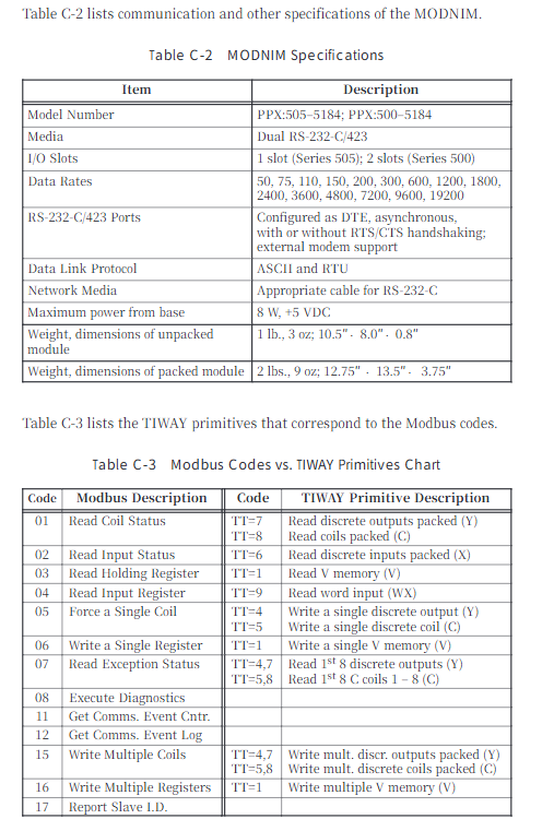
2.4 Communication components
Communication system: Supports SINEC L1 LAN PROFIBUS、 Industrial Ethernet, point-to-point connection
Communication Processor (CP): divided into LAN type and link/signal/log type, adapted for human-machine and machine machine communication
System configuration
3.1 Centralized Configuration
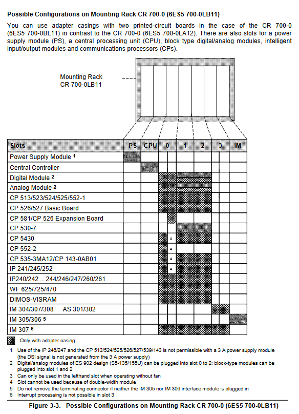
Structure: 1 central controller (CC)+up to 3 expansion units (EU)
Interface modules: IM 305 (supporting 1 EU, cable ≤ 1.5m), IM 306 (supporting 3 EU, cable ≤ 2.5m)
Power supply: EU takes power from CC through interface module, with a maximum power supply current of 2A (IM 306)
3.2 Distributed Configuration
Maximum distance: Depending on the interface module, it can reach up to 3000m
Interface modules: AS 301/302, IM 304/314, etc., supporting multiple EU extensions
Advantages: Reduce sensor/actuator wiring costs and install closer to the site
Programming and Functionality
4.1 Programming Fundamentals
Programming language: STEP 5, supports 4 representation methods, structured/linear programming
Program block types: Program block (PB), Function block (FB), Sequential block (SB), Data block (DB), Organization block (OB)
Execution method: Loop execution (OB1), interrupt driven, time controlled
4.2 Core Functions
Interrupt handling: Supports process interrupts, time interrupts, and response time can be calculated
Analog processing: compatible with multiple sensors, supports wire breakage detection and sampling, including FB250/251 matching blocks
PID control: up to 8 control loops, sampling time ≥ 100ms
Real time clock: Built in CPU 943/944, supports time related program execution
Installation and Startup
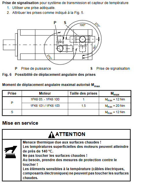
5.1 Installation Requirements
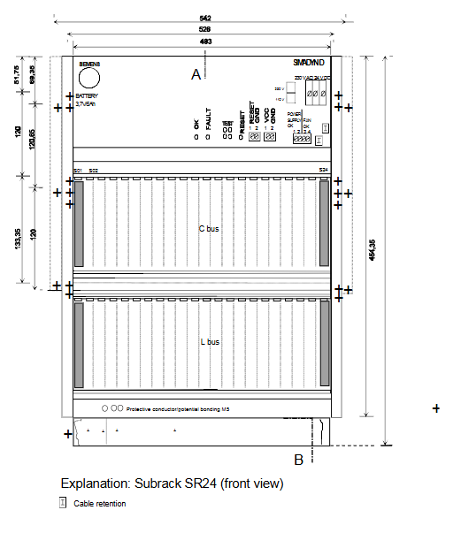
Mechanical installation: The module is fixed on the mounting bracket (CR/ER series), allowing for a 15 ° tilt installation. High power modules require a fan
Wiring specifications: Distinguish between control circuits (5V/5.2V/24V) and load circuits, with different wiring for floating/non floating modules
Electromagnetic compatibility: Cable grouping and wiring, shielded cable double ended grounding, potential bonding conductor cross-section ≥ 16mm ² (≤ 200m)
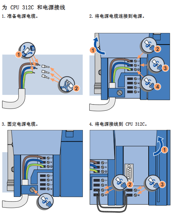
5.2 Startup steps
Overall reset: Clear program memory, data, and error IDs, restore system data to default values
Program transfer: Directly transferred through memory submodules or programmers, automatically loaded into internal RAM by CPU 943/944
Parameter settings: Determine timer/counter/flag retention, set scan monitoring time (default 500ms, maximum 2.55s)
Program testing: Use functions such as STATUS/VAR, FORCE, etc. to check I/O signals and program logic
Fault diagnosis
Diagnostic tools: ISTACK (Interrupt Stack) analysis, LED indicator lights, BSTACK (Block Stack) program tracking
Common faults: battery failure (BAU signal), scan time timeout (ZYK), I/O not ready (PEU), memory error
Solution: Replace the faulty module, retransmit the program, check the wiring and terminal resistance