Call us 24/7uaedcs@163.com
Welcome to the official website of CNIACS Automation Technology Co., Ltd!
Call us 24/7uaedcs@163.com

ABB INNIS01 Network Processing Module

Hardware Architecture

The ABB INNIS01 network processing module adopts a compact design with a sturdy and durable housing, which can adapt to the complex and changing environment of industrial sites, such as high temperature, humidity, strong electromagnetic interference and other scenarios. It integrates high-performance processors and abundant storage resources internally, with powerful data processing capabilities that can quickly parse, forward, and process network data; Storage resources provide strong support for the stable operation of modules and data caching, ensuring that data loss or processing delays do not occur even under high data traffic conditions. In addition, the module is equipped with multiple communication interfaces, including Ethernet interfaces, serial ports, etc., to facilitate connection with different devices and networks.

Core functions

Network data processing: The INNIS01 module can efficiently process various types of data in industrial networks, whether it is real-time process data, equipment status information, or control instructions, it can be quickly and accurately parsed and forwarded. In industrial automation production lines, it can quickly transmit real-time data collected by sensors to the control system, and at the same time send instructions issued by the control system to the executing agencies in a timely manner, ensuring the smooth operation of the production process.

Protocol conversion: Supports multiple industrial communication protocols, such as Modbus, Profibus, Ethernet/IP, etc. In practical industrial scenarios, devices from different manufacturers may use different communication protocols, and the INNIS01 module can achieve the conversion between these protocols, enabling seamless communication between different devices. For example, in a factory workshop containing multiple branded devices, this module can connect and exchange data between devices using Profibus protocol and systems using Ethernet/IP protocol, breaking down communication barriers between devices.

Network management and diagnosis: With powerful network management functions, it can monitor and manage devices in the network in real-time, including device status monitoring, network topology discovery, etc. When a network failure occurs, the module can quickly locate the fault point and send alarm messages through indicator lights or network management software to help technicians troubleshoot and solve problems in a timely manner, reducing system downtime.

NFI-NET is a unidirectional, high-speed serial data highway shared by all INFI 90 OPEN nodes. INFI-NET provides sophisti cated interfaces for data exchange.

This process control unit interface is made up of state-of-the-art INFI 90 OPEN modules.

INTENDED USER

Personnel installing, operating or maintaining the process control unit interface should read this instruction before performing any installation, operation or maintenance procedures.

Installation requires an engineer or technician with experience handling electronic circuitry and who is familiar with commu nication networks.

PROCESS CONTROL UNIT INTERFACE DESCRIPTION

The process control unit interface is made up of the INNIS01 Network Interface Slave Module (NIS) and INNPM11 Network

Processing Module (NPM). Through this interface the process control unit has access to INFI-NET. At the same time the NPM module communicates with the control modules via the Controlway.

The process control unit interface can support hardware redundancy (refer to Figure 1-1). In a redundant configuration,there are two NIS modules and two NPM modules. One pair of modules is the primary. If the primary modules fail, the backup modules come on-line. Redundant data highway com munication capability is a standard feature.

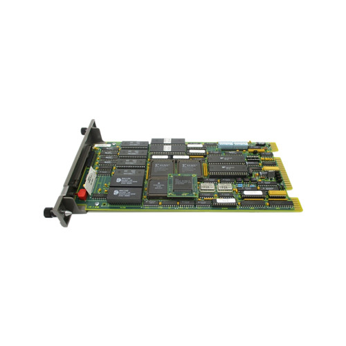
​INNIS01 NETWORK INTERFACE SLAVE MODULE

The NIS module is an I/O module that works in conjunction with the NPM module. This allows a node to communicate with any other node on the INFI-NET loop.

The NIS module is a single printed circuit board that occupies one slot in the module mounting unit. The circuit board con tains microprocessor based communication circuitry that enables it to interface with the NPM module.

Two latching screws on the faceplate secure the NIS module to

the module mounting unit. There are 16 LEDs on the faceplate

that display error codes and event/error counts.

The NPM module acts as a translator between INFI-NET and Controlway. The NPM module holds the process control unit database and directs the communication process between the modules residing on Controlway and the NIS module.

The NPM module is a single printed circuit board that occupies the slot adjacent to the NIS module in the module mounting unit.

The circuit board contains microprocessor based commu nication circuitry that enables it to interface with the NIS module and all Controlway modules.

Two latching screws on the NPM module faceplate secure the module in the module mounting unit. The faceplate contains eight CPU LEDs, a status LED, and a stop/reset pushbutton.

The NPM module has three card edge connectors for external signals and power (P1, P2 and P3). Connector P1 connects to common (ground), +5 VDC power, and the Controlway. Connector P2 connects the NPM module to the NIS module.

Connector P3 provides for communication between primary and backup process control unit interfaces.

The NPM module communicates with the NIS module within its process control unit through the I/O expander bus.

INNIS01 | ABB | Network Interface Slave Module

ABB MSET01 MODULE, SEQ OF EVENTS

ABB MSET01 MODULE, SEQ OF EVENTS

Core functions

The core function of ABB MSET01 module is event sequence recording, which can accurately capture the time and sequence of various events occurring in industrial systems. In industrial production environments, numerous devices work together, and once a malfunction or abnormality occurs, it is often accompanied by the occurrence of multiple related events. The MSET01 module can record the timing of each event with extremely high time resolution (usually up to milliseconds or even microseconds), accurate to one millionth of a second, providing critical data support for subsequent fault analysis and system optimization. For example, in the power system, when a short circuit fault occurs in the line, the MSET01 module can quickly record the accurate sequence and time of a series of events such as protection device action, switch tripping, and sudden changes in current and voltage, helping engineers quickly locate the cause of the fault and develop solutions.

Working principle

This module monitors the system status in real-time by connecting with on-site sensors, controllers, and other devices. When an event occurs, such as a sensor detecting a parameter exceeding a threshold or a change in device status, the MSET01 module will immediately trigger a recording mechanism to store the event type, status change information, and accurate timestamp data in the internal memory. It adopts a high-precision clock source to ensure the accuracy and consistency of time, and has the function of synchronizing with external clocks, such as synchronizing with standard time sources through GPS or Network Time Protocol (NTP), to ensure comparability of time recorded by MSET01 modules at different locations throughout the industrial system. At the same time, the module transmits the recorded event data to the monitoring system or data center through communication interfaces such as Ethernet, serial port, etc., making it convenient for operators to view and analyze.

Key advantages

High reliability: The MSET01 module adopts a sturdy and durable hardware design and highly stable software algorithms, which can operate stably in harsh industrial environments such as high temperature, humidity, strong electromagnetic interference, etc. It has a comprehensive self diagnostic function that can monitor its own working status in real time. Once a fault is detected, it can promptly issue an alarm signal to ensure the integrity and accuracy of event records.

Powerful data processing capability: capable of processing event inputs from multiple channels simultaneously, meeting the recording needs of a large number of events in complex industrial systems. Moreover, the module can quickly classify and filter events, only recording important event information, avoiding the accumulation of useless data, and improving data processing efficiency and analysis accuracy.

Flexible configuration and integration: Supports multiple communication protocols, making it easy to integrate with devices and systems from different manufacturers. Users can flexibly set the sampling frequency, event triggering conditions, communication parameters, etc. of the module through configuration software according to actual needs, to adapt to different industrial application scenarios.

Typical application scenarios

Power system: Used in power facilities such as substations and power plants to record changes in the operating status and fault information of power equipment, helping power operation and maintenance personnel quickly analyze the causes of faults, shorten power outage time, and improve the reliability and stability of the power system.

Petrochemical industry: Record key equipment status, process parameter changes, and other events in the production process, so that in case of abnormal situations, the entire process of the event can be traced, the production process can be optimized, and production safety can be guaranteed.

Industrial automation production line: Monitor the start stop, fault alarm, product quality inspection and other events of equipment on the production line, provide accurate data basis for production scheduling and equipment maintenance, and improve production efficiency and product quality.

IMSET01 | ABB Bailey | Sequence of Event Time Keeper Module

ABB IMSED01 main processor unit

IMSED01 is a crucial main processor unit in ABB 800xA systems, playing a central role in industrial automation processes. It provides solid and powerful support for various complex industrial applications with its outstanding performance.

Powerful processing capability

IMSED01 is equipped with a powerful processor with excellent computing power and response speed. It can easily handle complex control tasks and large amounts of data processing requirements. The multitasking and parallel operation modes greatly enhance the overall operational efficiency and flexibility of the system. Whether performing routine industrial process control or handling sudden complex working conditions, IMSED01 can respond quickly and accurately, ensuring the stable and efficient operation of the production process.

High availability design

Considering the strict requirements for system stability in industrial production, this controller specifically supports CPU redundancy function. In actual operation, once one CPU fails, another backup CPU will seamlessly take over the work immediately, ensuring uninterrupted system operation and minimizing downtime caused by hardware failures, providing reliable guarantees for the continuity of industrial production. This high availability design is particularly important in industries such as chemical, power, metallurgy, which require extremely high production continuity.

high reliability

IMSED01, which has obtained EMC certification, fully demonstrates its outstanding performance in electromagnetic compatibility. This means that it can operate stably and reliably in industrial environments filled with complex electromagnetic interference, greatly reducing the risk of system failures caused by electromagnetic interference. At the same time, its simple and easy-to-use design concept also enables operators to quickly get started, reducing problems caused by operational errors and further improving the reliability of the system.

Rich communication interfaces

In order to meet the needs of connecting and communicating with various devices, systems, and networks in different industrial scenarios, IMSED01 is equipped with a rich variety of communication interfaces. This includes Ethernet interfaces, which can achieve high-speed data transmission and facilitate communication with internal enterprise LANs and other devices with Ethernet interfaces; Serial communication interface, suitable for scenarios that do not require high data transmission rates but require long-distance transmission or connection with specific serial devices; The fieldbus interface can be connected to various fieldbus devices to build a complete industrial automation control network. Through these communication interfaces, IMSED01 can easily interconnect with other devices, achieve data sharing and collaborative work, and help enterprises build intelligent and efficient industrial production systems.

Hardware configuration details

CPU board: As the core component of IMSED01, the CPU board integrates a microprocessor and RAM memory. Microprocessors are responsible for executing various control instructions and data processing tasks, and their performance directly affects the running speed and processing capability of the entire processor unit. RAM memory is used to temporarily store data and programs during operation, ensuring that the system can quickly read and write data and ensuring smooth system operation. In addition, the CPU board is equipped with a real-time clock to provide accurate time reference for the system, which is crucial in some industrial applications that require strict time synchronization. At the same time, the LED indicator lights installed on the board can intuitively display the operating status of the equipment, making it convenient for operators to monitor and troubleshoot. The Initialize button is used to initialize the device when necessary, ensuring that the system can be restored to its normal initial state. In addition, the CompactFlash interface provides convenience for data storage and expansion. Users can insert CompactFlash cards according to their actual needs to expand the device’s data storage capacity.

Bottom plate: The bottom plate plays a crucial role in connecting and supporting various components in IMSED01. It is equipped with two RJ45 Ethernet ports (CN1, CN2) for connecting control networks and achieving high-speed data communication with other devices or systems through Ethernet. At the same time, the motherboard is also equipped with two RJ45 serial ports (COM3, COM4). Among them, port COM3 is an RS-232C port with modem control signals, which is widely used in scenarios where communication with modems or other devices with RS-232C interfaces is required. The other port COM4 is isolated and specifically used to connect configuration tools, ensuring that the device is not affected by other interference signals during configuration, and ensuring the stability and accuracy of the configuration process. It is worth mentioning that each substrate is equipped with a unique Ethernet address, which is like the device’s “ID card”, providing each CPU with a unique hardware identifier, making it easy to identify, manage, and communicate with devices in complex network environments.

Abb Imset01 Sequence Of Events Timing Module - Industrial Lynx

ABB IMMPI01 Multi functional Processor Interface

overview

ABB IMMPI01 is a multifunctional processor interface that plays a key role in the field of industrial automation. As an important connection hub in the system, it enables efficient data exchange and instruction transmission between different devices and systems, laying the foundation for the stable operation and precise control of industrial automation systems.

function characteristics

I/O interface processing: This interface module is mainly responsible for handling I/O interface tasks between the host and INICT03 module. In complex industrial automation systems, numerous devices require data exchange with the host. IMMPI01 ensures accurate and fast data transmission between the host and INICT03 module, achieving seamless integration between the devices and the core control part of the system.

Flexible communication interface support: IMMPI01 module supports SCSI or RS-232-C computer interfaces. RS-232-C is a common serial communication interface standard with wide applications. When communicating through the RS-232-C port, the module has strong flexibility and can serve as both a data communication device (DCE) and a data terminal device (DTE). This flexible role switching ability enables it to adapt to different types of device communication needs, whether it is connecting to computers, PLCs, or other industrial automation equipment, it can achieve stable data transmission. The SCSI interface, on the other hand, has the characteristic of high-speed data transmission and is suitable for scenarios that require high data transmission speed, such as connecting to storage devices or high-speed data acquisition devices.

Microprocessor communication circuit: The module adopts a microprocessor based communication circuit design. This circuit is integrated on a printed circuit board and can efficiently communicate with the INICT03 module through a ribbon cable connection. The microprocessor, as the core, processes and forwards data quickly, ensuring the stability and efficiency of communication. This design enables IMMPI01 to handle a large number of data transmission tasks in complex industrial environments, ensuring real-time responsiveness of the system.

physical property

Structural design: IMMPI01 module is an independent printed circuit board with dimensions of 3.7cm × 31.4cm × 17.8cm and a weight of approximately 0.26kg. This compact structural design allows it to be easily installed in module installation units, occupying only one slot of space, providing convenience for the spatial layout of the system, especially suitable for industrial control cabinets and other equipment with high space requirements.

Connector layout: The module is equipped with three card edge connectors for external signals and power, namely P1, P2, and P3. Connector P1 is responsible for connecting the common power supply and the+5 VDC power supply, providing stable power support for the normal operation of the module. Connector P2 has not been used in the current design, leaving space for possible future functional expansion. Connector P3 is used to connect the module to the NTMP01 terminal unit, enabling further connection and communication with other devices. In addition, there is a P6 connector specifically designed to connect the IMMPI01 module to the INICT03 module, ensuring the integrity of the data communication link.

application area 

Industrial automation production line: IMMPI01 plays a crucial role in large-scale industrial automation production lines such as automotive manufacturing and electronics manufacturing. It connects various production equipment, such as robots, automated assembly equipment, testing instruments, etc., with the host control system to achieve collaborative work between devices. For example, in the automotive manufacturing workshop, IMMPI01 can transmit the robot’s motion instructions and sensor feedback data to the host, while also conveying the host’s production plan and control instructions to the robot, ensuring precise assembly of automotive components, improving production efficiency and product quality.

Process control system: In the process control systems of industries such as chemical, power, and petroleum, IMMPI01 is used to connect various monitoring instruments and control equipment with the central control system. It can collect real-time analog signals such as temperature, pressure, flow rate, etc., and convert them into digital signals to transmit to the host for analysis and processing. At the same time, the control instructions issued by the host are transmitted to the executing mechanism, such as regulating valves, pumps, etc., to achieve precise control of the production process and ensure the safety and stability of the production process.

Intelligent Building Control System: In the field of intelligent buildings, IMMPI01 can be used to connect various automation devices inside the building, such as lighting systems, air conditioning systems, security systems, etc., with the central management system. Through it, centralized monitoring and management of building equipment can be achieved, and the operating status of equipment can be automatically adjusted according to actual needs, achieving the goals of energy conservation, comfort, and safety. For example, intelligent lighting management can be achieved by controlling the switch and brightness of the lighting system through IMMPI01 based on indoor and outdoor light intensity and personnel activity.

​Technical Parameter

Power requirements: The working power supply is+5 VDC, with a current consumption of 415 mA and a power of approximately 2.1 W. The stable power input ensures the reliable operation of the module under various working conditions.

Communication port: Equipped with 2 RS-232-C ports and 1 SCSI port, it meets the communication connection requirements of different devices and provides flexible data transmission channels.

Other parameters: The country of origin is Sweden, in compliance with relevant international standards, such as HS code 853701190, which is widely recognized and applied worldwide. It has a certain level of protection capability. Although the specific protection level is not specified, the design takes into account the needs of industrial environments and can resist a certain degree of interference such as dust and vibration, ensuring the normal operation of the equipment.

ABB Bailey IMMPI01 Module - Cambia Automation Limited

ABB IMMFP12 Multi-Function Processor Module

The IMMFP12 Multi-Function Processor Module is a powerful stand-alone controller for use in complex control applications.

It has the processing speeds and storage capabilities necessary for advanced control applications. 

The IMMFP12 module is a user-configurable device that receives process input and out put through a variety of analog and digital I/O modules.

This instruction manual provides information about how the IMMFP12 module functions and how to install, configure,operate, and troubleshoot the module.

The IMMFP12 Multi-Function Processor Module (MFP) is one of the workhorses of the INFI 90® OPEN control module line. 

It is a multiple loop analog, sequential, batch and advanced controller that provides powerful solutions to process control problems.

It also handles data acquisition and information processing requirements providing true peer-to-peer commu nications.

The comprehensive set of function codes supported by this module handles even the most complex control strategies.

The INFI 90 OPEN system uses a variety of analog and digital I/O modules to communicate with and control the process.

The MFP module communicates with a maximum of 64 modules in any combination (refer to Figure 1-1).

The MFP module has three operating modes: execute, configure and error. In the execute mode, the MFP module executes control algorithms while constantly checking itself for errors. When an error is found, the front panel LEDs display an error code corresponding to the type of error found. In the configure mode,it is possible to edit existing or add new control algorithms. In this mode, the MFP module does not execute control algorithms.

If the MFP module finds an error while in execute mode, it auto matically goes into error mode. Refer to the Section 4 of this instruction for operating mode details.

A one megabaud CPU to CPU communication link allows the MFP module to accommodate redundant processors.

This link enables a backup MFP module to wait in a hot standby mode while the primary MFP module executes the control algorithms.

If the primary MFP module goes off-line for any reason, a bumpless transfer of control to the backup MFP module occurs

CLOCK AND TIMER

The clock section provides the clock signals that drive the module at 16 megahertz. 

Additionally, this section supplies the lower order clock signals for the on-board serial links, and the system timer for uniform control algorithm execution. 

All clock signals originate from either the 32 megahertz or 7.3728 mega hertz oscillators on the multifunction processor module.

The timer section keeps the multifunction processor module task scheduling at the proper intervals. 

One of the UART devices used for serial communication contains the timer section

MEMORY

The MFP module contains 512 kilobytes of ROM memory, 512 kilobytes of random access memory (RAM) and 256 kilobytes of nonvolatile random access memory (NVRAM). 

​It is important to remember that only 347,712 bytes of RAM memory and 194,752 bytes of NVRAM memory are available for user config urations.

The ROM memory holds the operating system instructions for the microprocessor. 

The RAM memory provides temporary storage and a copy of the module configuration. 

The NVRAM memory holds the module configuration (control strat egy designed with function codes).

The ability to retain infor mation when power is lost makes this type of memory unique.

Back-up batteries in the NVRAM device that keep the memory active makes this possible.

A key feature of the RAM and ROM memory of the MFP module is that it requires only one wait state.

This means that the microprocessor need only wait one clock cycle before it can check the data in memory. 

This results in quicker operation.

I/O EXPANDER BUS

The I/O expander bus resides on the backplane of the module mounting unit. 

This bus, an eight bit parallel bus, provides the communication path for I/O data between control and I/O modules. 

It supports up to 64 low power I/O modules.

The bus uses a protocol designed by Elsag Bailey to ensure data integ rity. 

The bus bandwidth is 500 kilobytes per second, however actual throughput is about 100 kilobytes per second.

I/O SECTION

The input and output section interface allows the microproces sor to read the switches that tell it how to operate and what address it has. 

This section contains the latches whose outputs connect to LEDs one through eight and the status LED.

Additionally this section contains an output that desig nates this module as the primary module. 

Upon a failover, this output turns off and the backup module output energizes as it takes over. This output actuates an LED that indicates which module is the primary.

Additionally, the input and output section monitors the stop/reset pushbutton. 

Pressing the pushbutton once causes this section to bring the module to an orderly stop after completing

any input or output function currently in progress. Pressing the pushbutton a second time resets the module.

SERIAL CHANNELS

The MFP module contains two independent, general purpose serial channels. 

One use is for language support (C and BASIC). Each channel supports standard baud rates up to

19.2 kilobaud. The appropriate termination unit or termina tion module uses standard D-type connectors. 

The NTMP01,NIMP01, or NIMP02 termination device optically isolates these communication channels.

This optical isolation eliminates the need to tie chassis ground to system common and alleviates the potential of damage from ground currents. One channel can also be used as a RS-485 connection.

DMA SECTION

The microprocessor sets this section for direct memory access or DMA. 

The DMA section allows data being received or trans mitted over the various communication paths to be transferred directly to or from the RAM memory without microprocessor intervention. 

​This process is known as cycle stealing. It greatly reduces the overhead associated with the microprocessor doing

such data moves.

This circuitry is used for the higher speed communication paths where the microprocessor would be overloaded handling the data moves, specifically Controlway.

The 40-kilobaud station link and the redundancy link also use this feature.

IMMFP12 ABB Bailey Infi 90 Multi Function Processor Card PLC Spare Parts

ABB IMFEC12 Analog Input Module

ABB IMFEC12 Analog Input Module

The IMFEC12 module interfaces to conventional transmitters and standard analog inputs. It links process data and commu nication from field devices to all multifunction processors(MFP), or the IMMFC03, IMMFC04 and IMMFC05 multifunc tion controller (MFC) modules. The IMFEC12 module can be used as a direct replacement for the IMASI02 module; however,baseband communications are not supported.

The IMFEC12 High Level Analog Input (FEC) module inputs 15 channels of analog signals only to the multifunction processor(MFP) or multifunction controller (MFC) module.

The IMFEC11 High Level Analog Input (FEC) module inputs 15 channels of analog or frequency shift keyed (FSK) digital sig nals to the MFP or MFC module.

The IMFEC11 module per forms all the functions of the IMFEC12 module and also provides communication with the Bailey-Fischer & Porter line of FSK digital smart transmitters and other smart devices in a field bus or point-to-point configuration.

Figure 1-1 shows how the FEC module fits within the INFI 90

OPEN system

Installation and application personnel should have a solid background in electronic instrumentation and process control.

They should be familiar with proper grounding and safety pro cedures for electronic instrumentation. Operators should have a knowledge of the process and should read and understand this instruction before placing the module in operation.

The FEC module is an intelligent module, with on-board micro processor, memory, analog-to-digital converter and communi cation circuitry. The module is a single printed circuit board that occupies one slot in a module mounting unit (MMU). Two captive latches on the module faceplate secure it to the module mounting unit.

The module has three card edge connectors for external signals(transmitter inputs and communication), system communica tion (I/O expander bus) and power. The module receives input

through a cable connection to a termination unit (TU) or termi nation module (TM). Wiring from the field devices connect to terminal blocks on the termination unit or termination module.

The IMFEC11 circuit board has 18 jumpers; three jumpers that allow selecting the mode of operation and communication(J2, J3 and J4) and 15 jumpers that select voltage/current input (J6 through J20). A dipswitch setting (S1) holds the I/O expander bus address of the module.

This section explains the operation of the IMFEC1 Analog Input Module (FEC). The module does two major tasks. It provides an interface by which the controlling module (multifunction processor or multifunction controller module (MFP/MFC)can input analog process data from external devices or smart transmitters. It also serves as a communication link between the INFI 90 OPEN control system and field devices.

The IMFEC12 module accepts inputs from conventional trans mitters (BC, EQ and PT) and standard analog inputs of 4 to 20 milliamps, 1 to 5 VDC, 0 to 1 VDC, 0 to 5 VDC, 0 to 10 VDC and -10 to +10 VDC. The IMFEC11 has all the functionality of the IMFEC12 module but also provides FSK communications for interface to Bailey-Fischer & Porter smart transmitters and other smart devices

Upon receiving initialization from the controlling module(MFP/MFC), the FEC module stores that information in memory and checks the configuration of each input channel. If all input channels check good, operation begins. If the FEC module detects a configuration error, that error appears in the module status report.

Under normal operation, the controlling module sends trans mitter commands and requests process input data and status information from the FEC module. 

The FEC module continu ously reads each input channel, does the necessary conver sions and stores the data in memory. When the controlling

module makes a request for data, the FEC module sends it the most current information that it has in memory.

If a communication failure with one of the transmitters occurs,the FEC module works to restore communication while continuing normal operation. It checks the transmitter configura tion upon restoring transmitter communication and normal process control continues.

The on-board microprocessor and control logic coordinates module functions. The microprocessor has four main functions:

• Storing the digital data in random access memory (RAM).

• Coordinating analog-to-digital conversion through the ana log-to-digital control chip.

• Preparing digital commands to send to the smart transmitters (IMFEC11 only).

• Reading and sending data to the controlling module (MFP/MFC).

The microprocessor directly links to eight kilobytes of random access memory. This memory serves as a storage area for process data and transmitter configuration information.

The microprocessor coordinates analog-to-digital conversions through ADC circuitry. The microprocessor takes the converted process data it receives from the ADC circuitry and

places it into a memory buffer. It remains in memory until the controlling module makes a request for process data or the microprocessor updates it with a new value.

When the micro processor receives a request for process data, it transfers that data from the memory buffer to a first in first out (FIFO) shift register where the controlling module can access it through the I/O expander bus interface.

For IMFEC11 modules (FSK communications), the micropro cessor sends command signals to the transmitters through the module communication circuitry. The circuitry converts com mands from the microprocessor into FSK signals. The micro processor directs the command transmission to the proper channel.

The MFP module communicates with the FEC module over the I/O expander bus. An Elsag Bailey designed integrated circuit interfaces the microprocessor to the I/O expander bus. All MFP commands and process data pass through the I/O expander bus interface and first in first out inputs or outputs.

IMFEC12 ABB Bailey Infi 90 Symphony Analog Input Module 15 Point PLC ...

ABB IMDSO14 Digital Output Module

ABB IMDSO14 Digital Output Module

Preface

The IMDSO14 Digital Output module outputs 16 separate dig ital signals from the INFI 90® OPEN Strategic Process Manage ment System to a process.

These digital outputs are used by control modules to control (switch) process field devices.

There are five versions of the digital output module.

• IMDSO01/02/03.

• IMDSO14.

• IMDSO15.

This manual covers the (IMDSO14). The difference between the IMDSO14 module and the IMDSO01/02/03 is in the output circuitry, switching capabilities, and EMI protection circuitry.

Refer to product instruction I-E96-310 for information on the IMDSO01/02/03.

The difference between the IMDSO14 module and the IMDSO04 module is in the EMI protection circuitry. Addition ally, the IMDSO14 module will handle 24 or 48 VDC load volt ages; the IMDSO04 is for 24 VDC only. Refer to product instruction I-E96-313 for information on the IMDSO04 mod

ule.

The IMDSO14 module may be used as a direct replace ment for the IMDSO04 module.

The IMDSO15 module provides electromechanical relay contacts for field devices. Refer to product instruction WBPEEUI240754A0 for information on the IMDSO15 module.

INTRODUCTION

This section explains the procedures required to place the IMDSO14 Digital Output module into operation. It includes instructions on setting the address selection switch, setup and physical installation and wiring and cable connections. DO NOT PROCEED with operation until you read, understand and complete the steps in the order in which they appear.

SPECIAL HANDLING

NOTE: Always use the Elsag Bailey field static kit (part number 1948385 1), consisting of two wrist straps, ground cord assembly,alligator clip, and static dissipating work surface when working with

static sensitive devices.

The kit is designed to connect the techni cian and the static dissipating work surface to the same ground point to prevent damage to the static sensitive devices by electro static discharge.

Use the static grounding wrist strap when installing and removing modules. Static discharge may damage static sensi tive devices on modules in a cabinet. Use grounded equipment and static safe practices when working with static sensitive devices.

1. Use Static Shielding Bag. Keep the module in its static shielding bag until you are ready to install it in the system.Save the bag for future use.

2. Ground Bags before Opening. Before opening a bag con taining an assembly with static sensitive devices, touch it to the equipment housing or ground to equalize charges.

3. Avoid Touching Circuitry. Handle assemblies by the edges; avoid touching the circuitry.

4. Avoid Partial Connection of Static Sensitive Devices.Verify that all devices connected to the modules are properly grounded before using them.

5. Ground Test Equipment.

6. Use an Antistatic Field Service Vacuum. Remove dust from the cards if necessary.

7. Use a Grounded Wrist Strap. Connect the wrist strap to the appropriate grounding plug

8. Do Not Use Lead Pencils to Set Dipswitches. To avoid contamination of switch contacts that can result in unneces sary circuit board malfunction, do not use a lead pencil to set a dipswitch

MAINTENANCE

The reliability of any stand-alone product or control system is affected by the maintenance of the equipment. Elsag Bailey recommends that all equipment users practice a preventive maintenance program that will keep the equipment operating at an optimum level.

This section presents procedures that the customer should be able to perform on site. These preventive maintenance proce dures should be used as a guideline to assist in establishing

good preventive maintenance practices.

Personnel performing preventive maintenance should meet the following qualifications.

• Maintenance personnel should be qualified electrical tech nicians or engineers that know the proper use of test equipment.

• Maintenance personnel should be familiar with the module mounting unit, have experience working with process con trol systems, and know what precautions to take when working on live AC and/or DC systems.

PREVENTIVE MAINTENANCE SCHEDULE

Table 6-1 is the preventive maintenance schedule for the IMDSO14 digital output module. The table lists the preventive maintenance tasks in groups according to their specified maintenance interval. Instructions for tasks that require fur ther explanation are covered under PREVENTIVE MAINTE

NANCE PROCEDURES.

NOTE: The preventive maintenance schedule is for general purposes only. Your application may require special attention.

EQUIPMENT AND TOOLS REQUIRED

Tools and equipment required for maintenance procedures are:

• Antistatic vacuum.

• Screwdriver (medium length).

• Isopryl alcohol (99.5 percent electronic grade).

• Distilled water.

• Compressed air.

• Foam tipped swabs.

• Lint free cloths.

• Eberhard Faber (400A) pink pearl eraser. 

IMDSO14 ABB Bailey Infi 90 Symphony Digital Slave Output Module PLC ...

ABB IMDSI14 Digital Input Modules

The IMDSI1 Digital Input modules provide 16 separate digital signals into the INFI 90® OPEN system for processing and monitoring. It interfaces process field inputs with the INFI 90 OPEN Strategic Process Management System.

A contact clo sure or switch is an example of a device that supplies a digital signal. Control modules provide the control functions; I/O modules provide the inputs and outputs. 

Four variations of the IMDSI1 modules are presented in this instruction:

• IMDSI12 – 24 VDC, 48 VDC, 125 VDC or 120 VAC inputs.

• IMDSI13 – 24 VDC inputs.

• IMDSI14 – 48 VDC inputs.

• IMDSI15 – 125 VDC or 120 VAC inputs.

The IMDSI12 is the functional equivalent of the existing IMDSI02 module with the restriction that the IMDSI02 offers selectable debounce filter times of 1.5 milliseconds (fast) and 17 milliseconds (slow) and the IMDSI12 module offers only the 17 milliseconds (slow) debounce filter time. The slow debounce filter is used in the majority of digital input applications.

Any of the IMDSI1 modules may be substituted in place of an IMDSI02 where appropriate jumper settings are used. For example, an IMDSI13 module may be substituted for an IMDSI02 module that has all its jumpers set for 24 VDC with a slow debounce filter. Figure 1-1 shows the INFI 90 OPEN communication levels and the position of the digital input modules within these levels. 

This section explains the inputs and input circuitry, control logic, logic power and connections for the IMDSI1 Digital Input modules. The DSI is a digital input interface to a multi-function processor (MFP), multi-function controller(MFC), or logic master module (LMM).

These control modules provide the control functions. A control module communicates with its I/O modules on a I/O expander bus as shown in Figure 1-1. Each I/O module on the I/O expander bus has a unique address set by address dipswitch S1 (Fig. 2-1) Digital field inputs are voltages of 24 VDC, 48 VDC, 125 VDC or 120 VAC rms. These voltages indicate an energized (ON) field device; a 0 volt input indicates a de-energized (OFF) field device.

The DSI have a fixed input debounce filter for DC inputs to allow for contact debounce time (17 millisecond response time).

The IMDSI13 (+24 VDC) module and the IMDSI14 (+48 VDC)module have a fixed configuration and do not require any jumper selections. The IMDSI15 (+125 VDC/120 VAC) module has jumpers to select DC or AC mode. The IMDSI12 (+24, +48,+125 VDC or 120 VAC) module has jumpers to select the DC or AC mode and jumpers to select the working voltage. Refer to the Installation section for an explanation of the jumper con nections.

NOTE: Due to the number of pins on the P3 connector, twelve inputs are separate while the remaining two pairs share input termi nals.

The positive (+) side of point 7 and 8 are tied together in each group (refer to Table 5-3). These points must use the same contact voltage (24 VDC, 48 VDC, 125 VDC or 120 VAC) set by the jumpers on the IMDSI12 module, or according to the relevant IMDSI1 mod ule working voltage

Figure 2-1 is a block diagram illustrating signal flow through the module. The input isolation block consists of current limit ers and optocouplers to isolate the 16 field inputs from the module circuitry. The input circuits provide 1500 VDC isola tion between input and logic circuitry and other input chan

nels. Refer to Table 1-5.

Digital input high impedance provides additional (passive) pro tection from high energy transients of field digital inputs Figure 2-1.  Digital Input Module Block Diagram Input signal path and low isolation capacitance allow protec tion against fast transient-burst disturbance.

The threshold detection block circuits test the input voltage to determine if it is at the proper voltage level to indicate an ON or OFF state. The output of this comparator is sent to a read buffer in the control logic block. If an input is energized, it also causes a corresponding input status LED on the front panel to light.

The control logic block consists of buffers that hold the input and status byte values. The I/O expander bus interface allows the control module to read these bytes

When an input signal is present at the proper voltage level, a zener diode conducts (turns on) to cause current flow through an optocoupler. Configurable jumpers (on IMDSI12) or fixed resistors (on IMDSI13, IMDSI14 or IMDSI15) select the turn-on threshold and input voltage.

The optocoupler output causes a comparator output to go low.

This lights a corresponding status LED on the module front panel to indicate an energized input; the I/O expander bus interface transmits a logic 1 to the control module on the I/O expander bus.

When no input signal is present, no current flows through the optocoupler. The front panel LED does not light and the DSI transmits a logic 0 on the bus. Figure 2-2 shows the digital input circuit.  

NOTE: The components inside the dashed boxes in Figure 2-2 are mounted only on the module versions stated in the note.

IMDSI14 | ABB | Digital Slave Input Module

ABB HK-11 auxiliary contact

ABB’s profound accumulation in the field of industrial electrical can be traced back to the merger of ASEA and BBC in 1988. Since then, with its persistent pursuit of innovation and global resource integration capabilities, it has continuously broken through in the research and manufacturing of various electrical equipment. As an indispensable key component in electrical control systems, auxiliary contacts have also been extensively researched and optimized by ABB. The HK-11 auxiliary contact is the crystallization of its technical strength and manufacturing process in this field. Relying on ABB’s globally unified high standard research and development system and strict quality control, it is committed to providing reliable signal feedback and control expansion solutions for various electrical control systems.

​Product Overview

ABB HK-11 auxiliary contacts are auxiliary control components suitable for specific electrical equipment (such as some ABB motor circuit breakers, etc.), mainly used in industrial electrical control systems to achieve signal feedback of the main circuit status and expand control functions. It can work in conjunction with equipment such as contactors and circuit breakers in the main circuit, transmitting the on/off information of the main circuit to the control circuit through the opening and closing status of its own contacts, providing accurate equipment operation status signals for the control system. At the same time, it can be used to implement complex electrical control logic, such as interlocking control, sequential control, etc., enhancing the automation control capability of industrial electrical systems.

Specification parameters

Contact form: Usually a combination of 1 normally open (NO) and 1 normally closed (NC) contact, this configuration can meet various control logic requirements. The normally open contact closes when the device is powered on, while the normally closed contact opens when the device is powered on, making it convenient for engineers to flexibly design circuits according to actual control requirements.

Rated working voltage: It can adapt to a wide range of voltage levels, such as 690V AC at AC 50Hz or 60Hz; The rated working voltage of DC is generally 250V DC. This enables the HK-11 auxiliary contacts to be widely applied in industrial electrical systems of different power supply types and voltage specifications.

Rated working current: Its rated heating current has clear numerical specifications, such as up to 10A. This parameter determines the current that the auxiliary contacts can stably carry, ensuring that under normal working conditions, the contacts will not be damaged due to overheating and ensuring the reliability of electrical connections.

Electrical lifespan: With high electrical lifespan indicators, it can achieve up to 1 million electrical operation cycles under rated load conditions. This means that during long-term frequent use, the HK-11 auxiliary contacts can maintain stable performance, reduce the probability of failures caused by contact wear and aging, and lower equipment maintenance costs.

Mechanical lifespan: The mechanical lifespan is equally outstanding, reaching millions of operating cycles. This is due to the use of high-quality materials and precision manufacturing processes, ensuring that the contacts can maintain good mechanical performance during long-term and frequent mechanical actions, such as accurate closure and disconnection of contacts, flexibility of actions, etc.

Performance advantages

Reliable signal feedback: High quality contact materials such as silver alloy are used, which have good conductivity and resistance to arc erosion. When the main circuit equipment operates, it can quickly and accurately switch the contact state, stably transmit the on/off information of the main circuit to the control circuit, provide reliable feedback on the equipment operation status for the control system, and avoid control errors caused by inaccurate signal transmission.

Flexible control extension: The contact configuration of 1 normally open and 1 normally closed provides great flexibility for the design of electrical control systems. Engineers can easily construct various complex control logics using these contacts according to actual control requirements. For example, in the motor forward and reverse control circuit, interlocking control between the motor forward and reverse contactors can be achieved through HK-11 auxiliary contacts to prevent short circuit faults caused by the simultaneous closing of two contactors.

High compatibility and adaptability: It can adapt well to various electrical equipment from ABB and other brands. Whether it is ABB’s own motor circuit breakers, contactors, or other equipment that meets corresponding electrical standards, the HK-11 auxiliary contacts can achieve seamless connection and collaborative work, improving the convenience and compatibility of electrical system integration.

Durable and sturdy structural design: The structural design fully considers the complexity and strictness of industrial application environments, using high-strength insulation shell materials with good mechanical protection performance, which can effectively resist external mechanical impact, vibration, dust, moisture and other environmental factors, ensuring stable operation in harsh industrial environments.

precautions

Correct selection and installation: When selecting, it is necessary to choose the appropriate HK-11 auxiliary contact model based on factors such as the actual type of main circuit equipment used, voltage level, current size, and control logic requirements. During the installation process, strictly follow the product installation manual to ensure that the contacts are firmly installed, the wiring is correct and error free, and to avoid problems such as poor contact and short circuits caused by improper installation.

Suitable working environment: It should be installed in a dry, well ventilated, and suitable temperature environment. The working temperature range is generally -5 ℃ to+40 ℃, and the relative humidity should not exceed 85% (without condensation). Avoid placing it in places with high temperature, humidity, strong electromagnetic interference, or corrosive gases to prevent affecting the electrical performance and service life of the contacts.

Regular maintenance and inspection: Regularly inspect the HK-11 auxiliary contacts to see if there are any signs of wear, erosion, dust accumulation, etc. on the surface of the contacts. If severe contact wear or obvious arc marks are found on the surface, they should be cleaned or replaced in a timely manner. At the same time, check if the connecting cables are loose to ensure the reliability of the electrical connection. In addition, regular functional testing should be conducted on the electrical system where the auxiliary contacts are located to ensure that they can function properly during actual operation.

Similar model supplement

In ABB’s auxiliary contact product line, models similar to HK-11 include HK-10. HK-10 auxiliary contacts have certain similarities with HK-11 in basic functions and application scenarios, but there may be differences in specific contact forms, rated parameters, and other aspects. For example, HK-10 may only have a single configuration of normally open or normally closed contacts, which is suitable for some electrical systems with relatively simple control logic requirements; The combination of 1 normally open and 1 normally closed contact of HK-11 is more suitable for constructing complex control logic. When selecting, users need to comprehensively compare the characteristics and advantages of different models based on specific industrial application scenarios, control requirements, and budget factors, and choose the most suitable auxiliary contact products.

Application scenarios

Industrial motor control system: In the control circuits of various industrial motors, HK-11 auxiliary contacts are used to provide feedback on the motor’s operating status, such as the motor’s start, stop, overload protection actions, and other information. At the same time, it can be used to achieve forward and reverse interlocking control of motors, sequential start and stop control of multiple motors, etc., to ensure the safe and stable operation of industrial motor systems.

Power distribution system: In distribution equipment such as power substations and distribution rooms, auxiliary contacts can be used to indicate the opening and closing status of circuit breakers, isolating switches, and other equipment, providing intuitive equipment operation status information for power operation and maintenance personnel, facilitating timely understanding of the operation status of the power system, troubleshooting, and equipment maintenance.

Automated production line control system: On the automated production line, HK-11 auxiliary contacts work together with various automation equipment such as PLC, sensors, actuators, etc. By changing the contact state, the operating status signal of the equipment is transmitted to control units such as PLC to achieve automated monitoring and control of the production process. For example, on the production line, auxiliary contacts are used to control the start and stop of related equipment based on the conveying status of the product, ensuring the smooth progress of the production process.

ABB HK-11 Auxiliary Contact Reasonable price - SAUL ELECTRIC

ABB 3BDH000032R1 FI830F Fieldbus Module PROFIBUS-DP

Product Overview

ABB 3BDH000032R1 FI830F Fieldbus Module PROFIBUS-DP is a fieldbus module based on the PROFIBUS-DP protocol, mainly used for data communication and interaction between devices in industrial automation control systems. It can connect various on-site devices such as sensors, actuators, frequency converters, etc. to the PROFIBUS-DP bus, achieving fast and reliable communication between the devices and the main controller. Through this module, industrial automation systems can collect real-time data from on-site equipment and accurately transmit control instructions to various devices, thereby achieving precise control and management of the entire production process.

Specification parameters

Communication protocol: Following the PROFIBUS-DP protocol, this protocol is a widely used fieldbus standard in the field of industrial automation, characterized by fast communication speed, high reliability, and strong anti-interference ability. Supports multiple communication rates ranging from 9.6 kbps to 12 Mbps, allowing users to flexibly choose the appropriate communication rate based on actual application scenarios and device requirements.

Interface type: Equipped with standard PROFIBUS-DP interface, using DB9 connector for easy connection with PROFIBUS-DP bus cable.

Electrical parameters: The power supply voltage is 24V DC, with an allowable voltage fluctuation range of ± 20%, to adapt to the complex power supply environment of industrial sites; The power consumption of the module is relatively low, with a power consumption of about 5W during normal operation.

I/O channels: usually have multiple input/output channels, which can be flexibly expanded according to specific models and configurations, and can meet the needs of industrial automation projects of different scales.

Environmental parameters: The working temperature range is -25 ℃ to+60 ℃, the storage temperature is -40 ℃ to+85 ℃, the relative humidity range is 5% to 95% (non condensing), and it can operate stably in harsh industrial environments.

Performance advantages

Efficient and stable communication: Based on the PROFIBUS-DP protocol, the high-speed data transmission capability enables fast and accurate transmission of equipment data and control instructions, reducing communication delays and ensuring the real-time and stability of industrial automation systems. Even in complex industrial electromagnetic environments, excellent anti-interference performance can ensure the accuracy and completeness of data transmission, effectively avoiding data loss and errors.

Flexible Scalability: Supports multiple configurations and expansion methods, allowing users to easily increase or decrease the number of I/O channels according to actual project needs, achieving adaptation to industrial automation systems of different scales and complexities. At the same time, it can seamlessly integrate with various field devices and controllers from ABB and other brands, improving system compatibility and scalability.

Convenient diagnosis and maintenance: Equipped with comprehensive self diagnostic functions, it can monitor the working status and communication connection of modules in real time. When a malfunction occurs, the problem can be quickly located through indicator light status and diagnostic information, making it easier for technicians to troubleshoot and maintain in a timely manner. In addition, the installation and disassembly process of the module is simple and convenient, which can effectively reduce maintenance costs and downtime.

Precautions

Correct installation environment: It should be installed in a well ventilated, dry, and far away from strong electromagnetic interference sources, such as large motors, transformers, and other equipment. Avoid exposing the module to harsh environments such as high temperature, humidity, and corrosive gases to prevent affecting the electrical performance and service life of the module.

Reasonable network configuration: When building a PROFIBUS-DP network, it is necessary to ensure a reasonable network topology and correct connection of terminal resistors to ensure stable transmission of network signals. At the same time, it is necessary to plan the number of network nodes and address allocation reasonably to avoid address conflicts and communication congestion problems.

Regular maintenance and inspection: Regularly check whether the connecting cables of the module are loose or damaged, and ensure that the DB9 interface is firmly connected. Pay attention to the working status indicator lights of the module, and promptly detect and handle abnormal situations. In addition, regular software upgrades are conducted on modules to obtain the latest features and performance optimizations, improving module stability and compatibility.

Application scenarios

Manufacturing production line: In manufacturing production lines such as automobile manufacturing, mechanical processing, and electronic assembly, it is used to connect various sensors, actuators, PLCs, and other equipment on the production line to achieve real-time collection of production data and rapid transmission of control instructions. For example, this module can monitor the real-time operation status of production equipment, product quality inspection data, etc., and adjust equipment parameters in a timely manner according to production needs to improve production efficiency and product quality.

Power system automation: Used in power substations, power plants, and other power systems to connect various power instruments, protection devices, control equipment, etc., to achieve automated monitoring and control of the power system. Through the PROFIBUS-DP bus, the module can quickly and accurately transmit power parameters, equipment status information, etc., facilitating centralized monitoring and management of the power system, ensuring the stability and reliability of power supply.

Process industry automation: In the fields of chemical, petroleum, metallurgy and other process industries, it is used to connect various process control instruments, regulating valves, frequency converters and other equipment to achieve precise control and optimization of the production process. For example, in the chemical production process, modules can collect real-time process parameters such as temperature, pressure, and flow rate, and transmit the data to the control system to automatically adjust the production equipment according to the set process requirements, ensuring the safety, stability, and efficiency of the production process.

ABB Fieldbus Module PROFIBUS-DP FI830F 3BDH000032R1

Search for products

Back to Top
Product has been added to your cart