Call us 24/7uaedcs@163.com
Welcome to the official website of CNIACS Automation Technology Co., Ltd!
Call us 24/7uaedcs@163.com

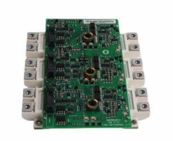
ABB IGBT MODULE KIT FS300R12KE3/AGDR-62C S 64717812

Model and Component Description

1. Core component composition

IGBT module:

Model: FS300R12KE3

Brand/Technology Platform: Infineon E3 series, an industrial grade IGBT with low loss and high reliability.

Function: As a power switching device, it is used for energy conversion in inverters and supports high-frequency switching and four quadrant operation.

Driver board:

Model: AGDR-62C

Function: Provide IGBT gate drive signals, integrate protection circuits (overcurrent, overheating, undervoltage detection), and adapt to the driving requirements of FS300R12KE3.

Product Code: 64717812 (ABB internal material code, used to identify kit configuration).

2. Model parameter analysis

FS300R12KE3:

FS: Infineon Standard IGBT Module

300: Rated current 300 A (RMS, RMS)

12: Rated voltage 1200 V

KE3: E3 technology platform, optimizing switch losses and short-circuit withstand capability

AGDR-62C:

AGDR: ABB Driver Board Series

62: Driver version compatible with 1200 V level IGBT

C: Coated board design to enhance corrosion resistance (suitable for humid or dusty environments)

Technical parameters

1. IGBT module (FS300R12KE3)

Electrical characteristics:

Rated voltage (Vces): 1200 V

Rated current (Ic, RMS): 300 A (@ Tc=80 ° C, sine wave load)

Peak current (Icm): 600 A (10ms pulse, duty cycle ≤ 1%)

Saturation voltage drop (Vce (sat)): typical value 1.8 V (@ Ic=300 A, Tj=25 ° C)

Switching frequency: up to 25 kHz (depending on heat dissipation conditions and load)

Mechanical and thermal characteristics:

Packaging: Press Fit press fit packaging, supports direct insertion into PCB or heat sink, reduces soldering stress

Dimensions: 122 mm x 44 mm x 14 mm (length x width x height)

Weight: Approximately 0.45 kg

Thermal resistance:R th(j−c)=0.06 K/W (shell to shell), requires aluminum or copper heat sink, recommended wind speed ≥ 5 m/s

Protection function: Built in freewheeling diode (FWD), supports short-circuit protection (detected by DESAT of the AGDR-62C driver board).

2. Drive board (AGDR-62C)

Power supply and interface:

Power supply voltage:+15 V DC (drive on)/-7 V DC (drive off), isolated power supply design

Signal input: Optocoupler isolation, compatible with 3.3 V/5 V TTL signals, input impedance ≥ 10 k Ω

Output current: Peak driving current ± 15 A (meets fast switching requirements)

Protection and monitoring:

Overcurrent protection (OC): triggered by detecting IGBT saturation voltage drop (DESAT), response time<1 μ s

Overheating protection (OT): Monitor module junction temperature, block drive signal when overheating occurs

Fault feedback: Provide fault output signals for optocoupler isolation (such as OC and OT status), which can be connected to the control system.

Application scenarios

1. Industrial transmission system

Inverter: Suitable for ABB ACS800, ACS580 and other series, used to drive 30-132 kW motors, commonly used in loads such as fans, pumps, conveyors, etc.

Servo system: high-precision servo drive, supporting vector control and position control, suitable for scenarios such as machine tools and robots.

Medium voltage application: By connecting multiple modules in series or parallel, it can be extended to medium voltage converters (such as 3.3 kV systems) for high-power equipment such as elevators and compressors.

2. Renewable energy

Photovoltaic inverter: a power module for string or centralized inverters, supporting MPPT tracking and grid connection.

Energy storage system: Battery Storage Converter (PCS), realizing bidirectional energy conversion between charging and discharging, supporting DC bus voltage range of 400-800 V.

Wind power converter: a converter module for doubly fed wind turbines, suitable for wide voltage inputs (400-690 V) and high reliability requirements.

3. Power electronic equipment

UPS power supply: The inverter module of the online UPS ensures uninterrupted power supply during power outages.

Welding power supply: IGBT type welding machine, supporting high-frequency pulse welding to improve welding quality and efficiency.

Industrial heating equipment: Induction heating power supply, used in metal heat treatment, melting and other scenarios, with a switching frequency of up to 20 kHz.

Installation and Maintenance Guide

1. Installation points

Mechanical installation:

Heat sink selection: It is recommended to use aluminum profile heat sinks (such as ABB original models) with a contact surface flatness of ≤ 5 μ m and coated with thermal conductive silicone grease (thickness 0.05-0.1mm).

Fixing method: Use M4 screws to tighten diagonally with a torque of 6-8 N · m to avoid uneven force on the module.

Electrical connection:

Main circuit: Low inductance copper bars with a spacing of ≥ 10mm are required for the DC bus (+/-) and motor output terminal (U/V/W) to avoid creepage.

Drive signal: Using twisted pair shielded cables with a length of ≤ 0.3 meters, the shielding layer is grounded at one end (near the drive board side).

Grounding requirements: The IGBT module housing (E terminal) should be directly connected to the system ground wire, with a grounding resistance of<0.1 Ω.

2. Maintenance and troubleshooting

Daily inspection:

Appearance: Check if there are cracks or burn marks on the module, and if the LED indicator light on the driver board is normal (green indicates normal, red indicates malfunction).

Electrical testing: Use a multimeter to measure the output voltage of the driver board (+15 V/-7 V), and observe the gate waveform with an oscilloscope (Vge rise/fall time should be ≤ 100 ns).

Cooling system: Fan speed ≥ 90% of rated value, radiator temperature ≤ 70 ° C (when ambient temperature is 25 ° C).

Common faults:

Overcurrent tripping: It may be caused by motor short circuit, drive board failure, or IGBT aging. It is necessary to investigate the main circuit and drive signal waveform.

Overheating alarm: Clean the dust on the radiator or replace the fan, and check whether the thermal grease is dry, cracked, or ineffective.

Module damage: manifested as a phase loss in the inverter output. Use a multimeter to check the resistance between C-E (normally unidirectional conduction, otherwise breakdown or open circuit).

Alternative models and compatibility

Same series upgrade options:

FS450R12KE3:450 A current level, other parameters are the same, suitable for power boosting scenarios.

FS300R12KL4: Infineon E4 series, with lower saturation pressure drop (Vce (sat) ≈ 1.6 V) and an efficiency improvement of about 5%.

Driver board replacement:

If it is necessary to adapt to other brands of IGBT (such as Mitsubishi, Fuji), the corresponding driver board needs to be replaced and the gate resistance and dead time parameters need to be re matched.

Safety and Compliance

authentication:

Compliant with RoHS 2.0 and REACH regulations, UL 1557 (power semiconductor) and CE certification (compliant with EN 60664-1 insulation requirements).

Safe operation:

After power failure, wait for at least 5 minutes and use a multimeter to confirm that the bus voltage is less than 30 V to avoid residual charges causing electric shock.

Wear an anti-static wristband during operation to avoid direct contact with the IGBT gate (G pole) and prevent damage from electrostatic discharge (ESD).

The faulty module must be marked as’ High Voltage Danger ‘and returned to ABB’s designated repair point. Disassembly by oneself is prohibited.

Ordering and Technical Support

Ordering information:

Material Number: 64717812

Packaging contents: IGBT module x 1, driver board x 1, installation screws x 4, thermal grease x 1 tube, quick guide x 1

FS300R12KE3/AGDR-72C S | ABB | IGBT Inverter Module

ABB IGBT MODULE KIT FS300R17KE3/AGDR-66C S 64717839

Model and component analysis

1. Core component composition

IGBT module:

Model: FS300R17KE3

Brand/Series: Infineon E3 series, which belongs to high-voltage and high-power IGBT modules.

Function: Used as a power switch for inverters, realizing the conversion of DC to AC electrical energy.

Driver board:

Model: AGDR-66C

Function: Provide gate drive signals for IGBT modules and integrate protection circuits (overcurrent, overheating, short circuit detection).

Product Code: 64717839 (ABB internal material code, used to uniquely identify the kit).

2. Meaning of Model Parameters

FS300R17KE3:

FS: Infineon Standard IGBT Module

300: Rated current 300 A (RMS, RMS)

17: Rated voltage 1700 V

KE3: E3 technology platform, low loss design

AGDR-66C:

AGDR: ABB Driver Board Series

66: Driver version compatible with high voltage level IGBT

C: Coated board (suitable for harsh environments, enhancing corrosion resistance)

Technical parameters

1. IGBT module (FS300R17KE3)

Electrical parameters:

Rated voltage (Vces): 1700 V

Rated current (Ic, RMS): 300 A

Pulse current (Icm): 600 A (10ms pulse width)

Saturation voltage drop (Vce (sat)): Typical value 2.1 V (@ Ic=300 A, Tj=25 ° C)

Switching frequency: up to 20 kHz (depending on heat dissipation conditions)

Mechanical characteristics:

Package: Press Fit, supports direct soldering or plug-in installation

Size: Approximately 121 mm x 44 mm x 14 mm

Weight: Approximately 0.5 kg

Heat dissipation requirements: thermal resistance R th(j−c)0.08 K/W (typical value), requires the use of an efficient radiator.

2. Drive board (AGDR-66C)

Supply voltage:

Main power supply:+15 V DC (driving IGBT on), -7 V DC (off bias)

Auxiliary power supply: isolated power supply, strong anti-interference ability

Interface features:

Optocoupler isolated input, compatible with TTL/CMOS levels

Fault feedback signal: Output overcurrent (OC) and overheat (OT) signals through LED or digital interface

Protection function:

Gate voltage monitoring (Vge undervoltage protection)

Active Miller clamp (suppresses oscillation)

Short circuit protection (DESAT detection, response time<1 μ s)

Application scenarios

1. Industrial sector

Medium and high voltage frequency converters: such as ABB ACS800 series models suitable for 1700 V level, used to drive high-power motors (such as mining machinery, steel rolling mills).

Renewable energy:

Wind power converter (doubly fed or full power converter), supporting high voltage ride through (HVRT) function.

Photovoltaic inverters (centralized or distributed) improve conversion efficiency and grid adaptability.

Power quality equipment:

Static Var Generator (SVG) and Active Power Filter (APF) are used for harmonic control and reactive power compensation.

2. Rail Transit and Ships

Traction inverter: a traction system for subways and high-speed trains that meets high reliability and vibration resistance requirements.

Ship electric propulsion: drives the propulsion motor, supports wide speed range and four quadrant operation.

3. Special power supply

High frequency heating power supply: The power module of induction heating equipment supports high switching frequency.

Pulse power supply: Pulse applications such as radar and particle accelerators that require fast switching.

Installation and maintenance

1. Installation points

Mechanical installation:

The module needs to be installed vertically on the heat sink, ensuring a flat contact surface, and using thermal conductive silicone grease (thickness ≤ 0.1mm).

Fixed torque: The screws need to be tightened in diagonal order, and the torque value should refer to the manual (usually 6-8 N · m).

Electrical connection:

Main circuit: Copper bars or low inductance cables are required for the DC bus (+/-) and output terminals (U/V/W) to reduce parasitic inductance.

Drive signal: using twisted pair shielded cables with a length of ≤ 0.5 meters to avoid electromagnetic interference (EMI).

Grounding: The driver board and module casing must be reliably grounded with a grounding resistance of<1 Ω.

2. Maintenance and troubleshooting

Daily inspection:

Visually inspect the surface of the module for cracks, erosion, or discoloration.

Measure the output voltage of the driver board: turn-on voltage+15 V ± 5%, turn off voltage -7 V ± 5%.

Cooling system: fan speed, radiator temperature (≤ 80 ° C is normal).

Common faults:

Overcurrent fault: It may be caused by motor short circuit, drive board failure, or IGBT aging, and an oscilloscope is needed to detect the gate waveform.

Overheating alarm: Failure of cooling fan, accumulation of dust in radiator, or failure of thermal grease, requiring cleaning or replacement.

Module damage: manifested as a phase loss in the inverter output, requiring a multimeter to detect module continuity (normally, unidirectional conduction between C-E).

Alternative models and compatibility

Upgraded models of the same series:

FS450R17KE4:450 A current level, E4 technology with lower losses, suitable for scenarios requiring higher power.

FS300R17KL4: 1200 V version, can be replaced if voltage requirements decrease (system voltage compatibility needs to be confirmed).

Driver board compatibility:

AGDR-66C is only compatible with IGBT at 1700 V level. If it is replaced with other voltage modules (such as 1200 V), the driver board (such as AGDR-61C) needs to be replaced synchronously.

Safety and Compliance

authentication:

Compliant with RoHS 2.0 environmental standards and certified by UL and CE safety regulations (please refer to specific documentation).

Compliant with IEC 60664-1 insulation standard, suitable for pollution level 2 environment.

Safe operation:

After power failure, wait for the capacitor to discharge (≥ 10 minutes) and use a multimeter to confirm that the bus voltage is less than 30 V.

Wear an anti-static wristband to avoid direct contact with IGBT pins (G is highly susceptible to electrostatic breakdown).

The faulty module needs to be professionally handled to avoid high-pressure residue or debris splashing during disassembly.

ABB IGBT MODULE KIT FS450R12KE3/AGDR-61C S 64635875

​Model analysis

Core components:

IGBT module: Model FS450R12KE3, belonging to Infineon’s high-power IGBT module, suitable for industrial grade inverter applications.

Driver board: Model AGDR-61C, a gate driver board designed for ABB to drive IGBT modules and ensure reliable switch control.

Product number: 64635875, is an internal ABB material number used to identify specific kit configurations.

Key parameters

IGBT module (FS450R12KE3):

Voltage/Current: 1200 V withstand voltage, 450 A rated current (RMS), suitable for medium power converters.

Technical features:

Adopting Infineon E3 series chips, with low saturation voltage drop (V CE (sat)) and efficient switching performance.

Compatible with short-circuit protection and temperature monitoring functions, with built-in freewheeling diode (FWD).

Packaging form: Press Fit technology, suitable for welding or crimping installation, to improve mechanical reliability.

Drive board (AGDR-61C):

Power supply voltage: usually ± 15 V DC, supports isolated driving, and has strong resistance to electromagnetic interference (EMI).

Interface: Suitable for IGBT module gate signal input, may include optocoupler isolation or digital signal interface.

Protection function: Integrated overcurrent, overvoltage, and overheating protection, supporting fault signal feedback to the control system.

Application scenarios

Industrial transmission system:

Suitable for ABB frequency converters (such as ACS800 series), servo drives, or medium to high voltage inverters, used for motor control (such as fans, pumps, rolling mills, etc.).

Renewable energy:

The power conversion process of photovoltaic inverters and wind power converters supports grid connected or off grid applications.

Power quality equipment:

Such as Static Var Compensators (SVC) and Active Power Filters (APF), used for harmonic suppression and reactive power regulation.

rail transit:

The converter module in subway and light rail traction inverters meets the requirements of high reliability and vibration resistance.

Kit composition and installation

Typical package contents:

IGBT module (FS450R12KE3) × 1

Drive board (AGDR-61C) x 1

Supporting hardware: Install screws, insulation gaskets, and thermal grease (used for heat dissipation between modules and heat sinks).

Documents: Installation guide, safety manual, electrical schematic diagram.

Installation points:

Mechanical installation: It needs to be fixed on the radiator to ensure reliable heat conduction path and torque compliance with specifications (usually 5-10 N · m).

Electrical connection:

Main circuit: Connect the DC bus (+/- DC) and motor output (U/V/W).

Control signal: The gate terminals (G/E) of the driver board and IGBT module are connected through shielded cables to avoid electromagnetic interference.

Safety precautions:

Wear an anti-static wristband during operation to prevent static electricity from damaging the IGBT chip.

Before supplying power to the driver board, it is necessary to confirm the voltage polarity to avoid module burnout caused by reverse connection.

Maintenance and troubleshooting

Daily maintenance:

Regularly inspect the surface of the module for cracks and burn marks.

Measure the output voltage of the driver board (normal ± 15 V) to ensure that the IGBT on/off voltage meets the requirements.

Check the cooling system (fan, radiator temperature) to ensure that the junction temperature (Tj) is below the maximum allowable value (usually 150 ° C).

Common faults:

Overcurrent fault: It may be caused by motor short circuit, load sudden change or drive board failure, and the main circuit and drive signal need to be checked.

Overheating alarm: Insufficient heat dissipation caused by blocked radiator or fan failure, requiring cleaning of the heat dissipation channel or replacement of the fan.

Module damage: manifested as unbalanced output of the inverter and triggering of short circuit protection. It is necessary to replace the IGBT module and check whether the drive board is synchronized with the fault.

Alternative models and compatibility

Compatibility module:

If FS450R12KE3 is out of stock, you can consider upgrading to the same series model (such as FS450R12KE4, higher efficiency) or other brand modules with the same parameters (driver board compatibility needs to be confirmed).

Driver board replacement:

AGDR-61C corresponds to a specific IGBT model, and when replacing it, it is necessary to ensure that the driving signal parameters (such as driving resistance and dead time) match.

Safety and Compliance

Certification: Compliant with RoHS environmental standards and may have obtained safety certifications such as UL and CE (please refer to specific documentation).

Safety regulations:

Follow ABB’s “High Voltage Safety Operation Manual” and wait for the capacitor to discharge (≥ 5 minutes) after power failure before performing maintenance.

The faulty module needs to be professionally handled to avoid contamination from high voltage residues or semiconductor fragments.

全新FS450R17KE3-AGDR71C IGBT模块 驱动板FS450R17KE3-AGDR-66C-阿里巴巴

ABB ACS800 inverter IGBT module

​Safety Notice

Applicable products: Suitable for ACS800-01/U1 and ACS800-02/U2 products.

Warning and Caution

Warning: Remind of situations that may cause serious injury or death and/or damage to equipment, such as dangerous voltage, electrostatic discharge, etc.

Attention: Remind users of special situations or events, or introduce relevant information on the topic, such as dangerous high voltage at motor cable terminals.

Installation and maintenance work

Only qualified electrical engineers are allowed to install and maintain transmission units.

It is prohibited to install or repair transmission units, motor cables or motors with electricity. After cutting off the input power, wait for at least 5 minutes until the intermediate circuit capacitor is discharged, and use a multimeter to measure and confirm the discharge before operation.

Do not operate control cables when the transmission unit or external control circuit is energized.

All insulation tests must be conducted with the cable disconnected, and ensure the correct phase sequence when reconnecting the cable.

grounding

Proper grounding is necessary to ensure the safety of personnel, reduce electromagnetic radiation and interference. The cross-sectional area of the grounding wire must meet safety regulations, and multiple equipment grounding terminals cannot be connected in series.

In scenarios that comply with European CE standards, cable entrances should maintain a 360 degree high-frequency grounding, and the cable shielding layer should be connected to the protective grounding wire (PE).

Do not install frequency converters with EMC filters in floating or high ground resistance power systems.

Mechanical Installation

The transmission unit is heavy and should not be carried by a single person. When carrying, do not let the front panel bear the weight and rely on lifting the back for transportation.

Ensure that drilling debris does not enter the transmission unit during installation, ensure sufficient cooling space, and do not fix the transmission unit by riveting or welding.

operate

Before debugging the transmission unit, ensure that the motor and driven equipment are suitable for operation within the speed range provided by the transmission unit.

Do not activate the automatic fault reset function of standard applications in situations where danger may occur.

Do not use the main power circuit breaker to control the start and stop of the motor. Instead, use control commands from the control panel keys or transmission unit I/O board.

Permanent magnet motor

When ACS800 is used to drive permanent magnet motors, only scalar control mode can be used.

When the permanent magnet motor is running, do not operate the transmission unit, as its operation transfers electrical energy back to the intermediate circuit. Even if the inverter is not working, the power supply will still charge the transmission system.

During installation and maintenance, use a fuse switch to disconnect the motor from the transmission unit. If possible, lock the motor shaft, connect the motor connection terminals together, and ground them.

Do not operate the permanent magnet motor at speeds higher than the rated speed to avoid overvoltage and capacitor bank rupture.

Product Overview

ACS800-01/U1: A wall mounted transmission unit used to control low-voltage AC asynchronous motors, with different external specifications (R2~R6), protection levels including IP21 (NEMA1) and IP55 (NEMA4, indoor only), etc. The control panel is CDP312R, including printed circuit boards such as main circuit board (RINT), motor control and I/O control board (RMIO), etc. The motor control mode can choose direct torque control (DTC) or scalar control.

ACS800-02/U2: There is relatively little mention in the document, and the external specifications are R7 and R8. Other information can refer to the relevant content of ACS800-01/U1. Some chapters of the two are common, such as safety instructions, electrical installation design, and braking resistors.

Installation

Mechanical Installation

Unpacking and inspection: After unpacking, check for any damage to the appearance, verify if the nameplate of the frequency converter matches the order, and check if the optional modules and equipment are complete.

Preparation before installation: Install vertically, place the radiator against the wall, check if the walls and floors of the installation site meet the requirements, ensure that there is enough space around the transmission unit for cooling air circulation, facilitate maintenance and repair, and pay attention to the space requirements when placing equipment of different protection levels up and down.

Installation method: including wall mounted installation and cabinet installation. Wall mounted installation requires marking the installation hole position with a punching template, fixing screws or bolts, installing the transmission unit and tightening it; Attention should be paid to the horizontal installation distance between the frequency converters when installing inside the cabinet, to prevent the recirculation of cooling air, and to set up air baffles.

Electrical installation design

Motor compatibility check: Ensure that the rated voltage and current of the motor meet the requirements, and avoid the rated voltage of the motor being less than 1/2 of the rated input voltage of the transmission unit or the rated current being less than 1/6 of the rated output current of the transmission unit.

Protecting motor windings and bearings: The output pulse voltage of the transmission unit may affect the motor insulation and bearings. ABB du/dt filters, common mode filters, etc. can be used to reduce the impact. Suitable filters and insulated bearings should be selected according to the motor type and power.

Power supply system connection: A manually operated circuit breaker can be installed between the AC power supply and the transmission unit, which must comply with relevant standards, such as using category AC-23B, etc; The input cable needs to be equipped with a fuse group, and the fuse model should be selected according to local safety regulations, input voltage, and rated current of the transmission unit.

Cable selection and wiring: The main power and motor cables need to be selected according to local regulations to meet the requirements of load current and temperature. The protection ground cables need to consider inductance and impedance limitations; It is best to use shielded cables for control cables, with separate routing for analog and digital signals to avoid long-distance parallel routing. When crossing, the angle should be 90 degrees.

electrical installation

Insulation performance inspection: Check the insulation performance of the motor and motor cables, disconnect the transmission unit from the main power supply, use a 1kV insulation meter to measure the insulation resistance of each relative protective ground, and the resistance value should be greater than 1 megohm.

Power cable wiring: Determine the length of wire stripping according to the external specifications, ground the cable shielding layer, connect the main power cable and motor cable to the corresponding terminals, and fix the junction box cover and front cover.

Control cable wiring: Thread the control cable through the entrance hole and connect it to the relevant detachable terminals on the RMIO board, ensuring a secure connection, grounding the shielding layer, and fixing the control cable and front cover.

Maintenance

Maintenance Cycle

Capacitor update: once a year when stored.

Temperature inspection and cleaning of radiator: Depending on the dust content in the environment, it should be done every 6-12 months.

Cooling fan replacement: Replace every five years, and replace spare fans for IP55 units and some IP21 units every three years.

Maintain content

Cleaning of radiator: Remove the cooling fan, use clean and dry compressed air to blow the radiator from bottom to top, while using a vacuum cleaner to absorb dust at the air outlet, and then install the cooling fan.

Cooling fan inspection: Pay attention to the noise of the fan bearings and the temperature of the radiator. Replace them in a timely manner when signs of damage appear, and use ABB designated spare parts.

Capacitor inspection: Electrolytic capacitors are used in the intermediate circuit, with a service life of about 100000 hours. Damage is often accompanied by the main power fuse melting or fault tripping. If there is suspicion of damage, contact the ABB representative office and use designated spare parts.

LED indication: The LED lights on the RMIO board and control panel installation components can indicate faults and normal power status.

Technical data

IEC level: lists the rated capacity, external specifications, air flow rate, heat loss, and other data of different models of ACS800-01 under 50Hz and 60Hz grid power supply.

Capacity reduction

Temperature induced capacity reduction: When the ambient temperature is between+40 ° C and 50 ° C, for every 1 ° C increase, the rated output current decreases by 1%. The rated current Icont.max is not allowed to be applied in environments exceeding 40 ° C.

Capacity reduction caused by altitude: When the altitude is between 1000-4000m, the rated current decreases by 1% for every 100m increase. If it exceeds 2000m, consult the local ABB dealer or office.

Main power cable fuse: provides cable specifications, fuse models, parameters, etc. corresponding to different models of ACS800-01.

Cable entry hole: information such as terminal size, cable diameter, and tightening torque for different external specifications.

Size, weight, and noise: The size, weight, and noise data of each external specification under different protection levels.

Motor wiring: parameters such as voltage, frequency, current, power limit, and recommended maximum motor cable length.

Efficiency and cooling: The efficiency is approximately 98% of the rated power, and the cooling method is an internal fan with a flow direction from the bottom to the top.

Protection level and environmental conditions: Protection levels include IP21 and IP55, as well as operating conditions such as environmental temperature, relative humidity, and pollution level.

Materials and applicable standards: Information on materials such as transmission unit casing and packaging boxes, following international standards such as EN50178, EN60204-1, etc.

Braking resistor

Configuration and selection: Transmission units with external specifications of R2 and R3 include built-in brake choppers, R4 and larger brake choppers are optional (model+D150), and resistors are additional components; When selecting the transmission unit/chopper/resistor, it is necessary to calculate the braking power to ensure that the resistor resistance and heat loss capacity meet the requirements.

Installation and wiring: All resistors must be installed outside the transmission unit module, with flame-retardant materials nearby. They should be connected using cables of the same model as the input cables of the transmission unit, with a maximum allowable length of 10m. The shielding layer should be properly grounded.

Protection and debugging: It is recommended to configure the main circuit contactor for external specifications R2~R5, and whether R6, R7, and R8 are needed depends on the selection situation; A thermal switch should be installed inside the braking resistor and connected to the digital input port as an external fault interlock signal; Activate the brake chopper function during debugging, turn off the overvoltage control function, and check the resistance value setting.

ALSTOM LE109A-1 Controller Module

Brand background

As a globally renowned giant enterprise in the fields of power and rail transportation, ALSTOM has a profound technical foundation and rich industry experience. Since its establishment, we have been committed to providing advanced technological solutions and high-quality products to global customers. In the field of industrial automation control, ALSTOM has established an excellent brand image through continuous innovation and research and development investment. Its products are widely used in various complex industrial scenarios and are known for their reliability and high performance. The ALSTOM LE109A-1 Controller Module is a typical product in the field of industrial control modules.

Core functions

Logical control: capable of executing complex logical operations, processing input signals according to preset control logic, and outputting corresponding control instructions to achieve precise control of industrial equipment. For example, in the automatic production line, according to the input signals of different sensors, control the start and stop of motors, the opening and closing of valves and other equipment actions.

Data collection and processing: It can collect real-time data from various on-site sensors, such as analog data such as temperature, pressure, flow rate, as well as digital data such as equipment status. After preprocessing operations such as filtering and converting the collected data, it is stored in internal memory for subsequent analysis and decision-making.

Communication function: Through the built-in communication interface, data exchange is carried out with the upper computer, other controllers, and on-site intelligent devices. On the one hand, uploading equipment operation data and status information to the upper computer for real-time monitoring by operators; On the other hand, it receives control instructions issued by the upper computer to achieve remote control functions.

Event recording and alarm: With event recording function, it can record key events during equipment operation, such as equipment start stop time, fault occurrence time and type, etc. When an abnormal situation is detected, an alarm signal can be triggered in a timely manner to notify the operator through indicator lights, buzzers, or communication networks, so as to quickly respond and handle the fault.

Working principle

The operation of ALSTOM LE109A-1 Controller Module is based on microprocessor technology. When external sensor signals are input to the input interface of the module, they first pass through the signal conditioning circuit to convert signals of different types and amplitudes into standard signals suitable for microprocessor processing. The microprocessor performs logical operations, data processing, and other operations on input signals according to pre written and stored control programs in internal memory. The calculation results are converted into control signals that can drive external actuators (such as relays, contactors, etc.) through the output interface circuit, thereby achieving control of industrial equipment. Throughout the entire work process, the communication module is responsible for exchanging data with external devices, sending out internal operational data, and receiving control instructions from external devices. At the same time, the event recording and alarm module monitors the real-time operation status of the system. Once any abnormalities are detected, relevant event information is immediately recorded and an alarm signal is issued.

Key advantages

High reliability: Using industrial grade electronic components and advanced manufacturing processes, rigorous quality testing and reliability testing ensure long-term stable operation in harsh industrial environments. For example, in environments such as high temperature, high humidity, and strong electromagnetic interference, normal working performance can still be maintained, reducing equipment downtime and improving production efficiency.

Powerful processing capability: equipped with high-performance microprocessors and large capacity memory, capable of quickly processing complex control logic and large amounts of data. When facing high-speed automated production lines or large-scale industrial control systems, being able to respond promptly and accurately execute control tasks ensures the efficient operation of the system.

Flexible Scalability: Provides rich input/output interfaces and communication interfaces, making it convenient for users to expand the system according to their actual needs. It can easily connect more sensors, actuators, and other intelligent devices to upgrade and optimize system functions, meeting the constantly changing needs of different industrial application scenarios.

Easy to maintain: The module has self diagnostic function, which can monitor its own working status in real time, quickly locate the fault point after discovering the fault, and facilitate quick repair by maintenance personnel. At the same time, adopting modular design, each functional module is relatively independent, and can be easily replaced in case of failure, reducing maintenance costs and time.

precautions

Installation environment: It should be installed in a dry, well ventilated, non corrosive gas and strong electromagnetic interference environment, avoiding direct sunlight. The installation location should be far away from heat sources and water sources to ensure the normal working temperature and humidity conditions of the module.

Electrical connection: When making electrical connections, be sure to disconnect the power supply and strictly follow the wiring diagram for correct wiring. Pay attention to distinguishing between input and output interfaces to avoid module damage or equipment failure caused by incorrect wiring. After the wiring is completed, it is necessary to carefully check the firmness of the wiring to prevent problems such as loose connections and poor contact.

Software programming: When writing and downloading control programs, the programming software and tools provided by ALSTOM should be used, and relevant programming specifications should be followed. Ensure the correctness and stability of the program, and avoid device malfunctions or system failures caused by program errors. At the same time, regularly backup the program to prevent data loss.

Daily maintenance: Regularly clean the module to prevent dust accumulation from affecting heat dissipation and electrical performance. Check the working status indicator lights of the module and observe for any abnormal flashing or extinguishing. Regularly conduct functional testing on modules to ensure that all functions are functioning properly. If any abnormalities are found, the machine should be stopped for inspection and maintenance in a timely manner.

Application scenarios

Industrial automation production line: widely used in various automated production lines such as automobile manufacturing, electronic equipment manufacturing, food and beverage processing, etc. Responsible for logical control and data collection of various equipment on the production line, such as robots, conveyors, processing equipment, etc., to ensure efficient and stable operation of the production line, improve production efficiency and product quality.

Power system: Used in power plants, substations, and other electrical facilities to monitor and control the operational status of electrical equipment. For example, the start stop control, parameter monitoring, and fault alarm of equipment such as generators, transformers, and circuit breakers ensure the safe and reliable power supply of the power system.

Intelligent building: In the intelligent building control system, it is used to achieve automated control of lighting, air conditioning, elevators, water supply and drainage equipment inside the building. By collecting various sensor data such as indoor temperature, humidity, and light intensity, the device’s operating status is automatically adjusted according to preset control strategies, achieving energy conservation, consumption reduction, and improving the intelligent management level of buildings.

Transportation: In the field of rail transit, it can be used for the operation control and monitoring system of trains such as subways and light rails. Accurately control the traction, braking, door control and other functions of the train, while collecting real-time train operation data to ensure the safe and on-time operation of the train. Used in transportation hubs such as ports and airports to control the operation of cargo loading and unloading equipment, transport vehicles, etc., and improve transportation efficiency and management level.

GE LE108A-3 industrial PLC (Programmable Logic Controller) Good quality ...

Alstom UT150 Temperature Controllers

Overview

ALSTOM’s UT150-1 is a device with significant application value in the industrial field. From the model perspective, UT150-1 has clear markings, making it easy to identify and configure in various industrial systems.

In terms of application, UT150-1 is mainly used in DCS/PLC industrial control systems. In these systems, it plays a crucial role in facilitating the stable operation of the entire industrial control process. In order to ensure performance, the device adopts a series of advanced measures, such as digital filtering and power frequency shaping sampling. This technology can effectively eliminate periodic interference, ensure the accuracy of data acquisition, avoid signal deviation caused by interference, and thus ensure the stable operation of the control system. At the same time, UT150-1 also uses measures such as timed calibration of reference point potentials to prevent potential drift. Potential drift may affect the normal working state of equipment, and this measure can adjust the potential in a timely manner to maintain stable operation of the equipment.

NOTE

To install the controller, select a location where:

1. No-one may accidentally touch the terminals;

2. Mechanical vibrations are minimal;

3. Corrosive gas is minimal;

4. The temperature can be maintained at about 23°C with minimal fluctuation;

5. There is no direct heat radiation;

6. There are no resulting magnetic disturbances;

7. The terminal board (reference junction compen sation element, etc.) is protected from wind;

8. There is no splashing of water; and

9. There are no flammable materials

Never place the controller directly on flammable items.

If the controller has to be installed close to flammable items or equipment, be sure to enclose the controller in shielding panels positioned at least 150mm away from each side.

These panels should be made of either 1.43mm thick metal plated steel plates or 1.6mm thick uncoated steel plates.

Mount the controller at an angle within 30° from horizontal with the screen facing upward. Do not mount it facing downward.

CAUTION

1) Before you start wiring, turn off the power source and use a tester to check that the controller and cables are not receiving any power in order to prevent electric shock.

2) For safety, be sure to install a circuit breaker switch (of 5A and 100V AC or 220V AC, and that

conforms to IEC60947) near the instrument so as to be operated easily, and clearly indicate that the

device is used to de-energize the instrument.

3) Wiring should be carried out by personnel with appropriate electrical knowledge and experience

IMPORTANT

1) Use a single-phase power source. If the source has a lot of noise, use an isolation transformer for the primary side and a line filter (we recommend TDK’s ZAC2205-00U product) for the secondary side.

When this noise-prevention measure is taken, keep the primary and secondary power cables well apart.

Since the controller has no fuse, be sure to install a circuit breaker switch (of 5A and 100V AC or 220V AC, and that conforms to IEC standards) and clearly indicate that the device is used to de-energize the controller.

2) For thermocouple input, use shielded compensating lead wires. For RTD input, use shielded wires which have low resistance and no resistance difference between the 3 wires. See the table given later for the specifications of the cables and terminals and the recommended products.

3) The control output relay cannot be replaced even though it has a limited service life (100,000 relay

contacts for the resistance load).  Thus, an auxiliary relay should be used so that the load can be turned on and off.

4) When using an inductive load (L) such as an auxiliary relay and solenoid valve, be sure to insert a CR filter (for AC) or diode (for DC) in parallel as a spark-rejecting surge suppressor to prevent malfunctions or damage to the relay.

5) When there is the possibility of being struck by external lightening surge, use the arrester to protect the instrument.

NOTE

• Always fix a terminal cover bracket to the UT150 controller before wiring if an optional anti-electric

shock terminal cover (part number: L4000FB) is used.

• Two types of optional anti-electric-shock terminal covers (part numbers T9115YE and T9115YD) are

available for the UT152 and UT155 controllers, respectively.

Field and purpose

As a globally renowned enterprise in the fields of rail transit, electricity, etc., Alstom’s UT150-1 control board is commonly used in the control systems of rail transit vehicles, such as subways, light rails, trains, etc., to achieve various control functions of the vehicles, ensuring the safe operation and efficient performance of the trains. For example, it may be responsible for controlling important functions such as traction, braking, speed regulation, and door opening and closing of the train.

Working principle

Signal processing and transmission: The control board receives signals from various sensors and operating devices of the train, such as speed sensors, position sensors, driver operation handles, etc., processes and analyzes these signals, and then sends control signals to the corresponding actuators according to preset logic and algorithms to achieve precise control of the train’s operating status.

Communication and network connection: Through specific communication protocols and network interfaces, the UT150-1 control board interacts and communicates with other systems and devices on the train, such as the central control system, traction system, braking system, etc., to share information and work together to ensure the coordinated operation of the overall train system.

FEATURES

High reliability: Adopting redundant design, fault-tolerant technology, and highly reliable electronic components to ensure stable operation in complex operating environments, reduce the probability of failures, and ensure the safety and reliability of train operation.

High real-time requirements: Real time response is required for train control, which can react to various signals and events in a very short time to achieve precise control of train operation and meet the safety and efficiency requirements of train operation.

Strong anti-interference ability: With good electromagnetic compatibility, it can work normally in the complex electromagnetic environment on the train, without being affected by electromagnetic interference from other devices, and without causing interference to other devices.

Maintenance

Regular inspection: It is necessary to regularly inspect the UT150-1 control board, including visual inspection, connection component inspection, circuit board status inspection, etc., to discover possible physical damage, looseness, corrosion and other issues.

Cleaning and dust removal: Keep the control board clean, regularly remove dust and debris, and prevent dust accumulation from affecting heat dissipation and circuit performance.

Software updates and upgrades: With the development of technology and changes in train operation requirements, it is necessary to timely update and upgrade the software of the control board to fix vulnerabilities, optimize performance, add new features, etc.

Preventive measures for configuring REX 521 protective relay

Basic configuration preparation

Clarify application scenarios and requirements

Determine the protected objects: lines, transformers, motors, etc. Different objects require corresponding protection functions to be enabled (such as motors requiring startup monitoring and thermal overload protection).

System grounding method: neutral point directly grounded, grounded through arc suppression coil, or ungrounded system, affecting the configuration of grounding fault protection (such as high resistance grounding requiring REF1A function to be enabled).

Short circuit current calculation: Calculate the maximum/minimum short-circuit current based on the system impedance, which is used to set the overcurrent protection threshold.

Hardware configuration verification

Confirm model and version: Check if the hardware version (Basic/Medium/High/Sensor) matches the requirements, such as the need to configure an additional adapter for IEC 61850 communication.

I/O interface allocation: Reasonably plan digital inputs (DI) for status acquisition (such as circuit breaker position), digital outputs (DO) for tripping/alarm, and reserve backup interfaces.

Power compatibility: Ensure that the power supply voltage (DC 18-265V/AC 85-240V) is consistent with the site to avoid misoperation caused by undervoltage.

Key points for setting protection functions

Current protection parameter setting

Overcurrent protection (3I>):

Action current: Set according to the normal load current, usually 1.2-1.5 times the rated current.

Time characteristics: Choose definite time (DT) or inverse time (IDMT) according to system selectivity requirements, and the inverse time curve can be selected according to IEC or ANSI standards.

Differential protection (if any):

Balance coefficient: automatically calculated based on transformer ratio and wiring group to ensure zero differential current during normal operation.

Braking coefficient: usually set to 0.3-0.5 to prevent misoperation in case of faults outside the area.

Voltage and frequency protection

Overvoltage/undervoltage protection (3U>, 3U<<):

Action value: Overvoltage is generally 1.1-1.3 times the rated voltage, and undervoltage is 0.7-0.9 times the rated voltage.

Delay: Set according to the allowed voltage fluctuation time of the system, such as the need for motor restart.

Frequency protection (f1/f2):

Action value: Under frequency is generally 47-49Hz, over frequency is 51-52Hz.

Special function: Enable df/dt change rate detection to suppress system oscillation triggering errors.

Earth fault protection

Neutral point grounding method:

Direct grounding system: adopting zero sequence current protection (Io>), the operating current is set to avoid the maximum unbalanced current.

Non directly grounded system: adopting zero sequence voltage protection (Uo>) or directional zero sequence current protection (67N).

High resistance grounding fault: Enable REF1A function to detect high resistance grounding by comparing the sum of neutral point current and three-phase current.

Special function configuration

Automatic reclosing (O ->I):

Overlap frequency: generally 1-3 times, permanent faults require locking of overlap.

Dead time: adjustable from 0.2-300s seconds, which should be greater than the detachment time of the fault point (usually 0.5-1 seconds).

Circuit Breaker Failure Protection (CBFP):

Starting condition: After the tripping command is issued, there is no feedback change in the position of the circuit breaker.

Action delay: 100-1000ms, which should be greater than the inherent opening time of the circuit breaker.

Communication and System Integration

Protocol selection and parameter configuration

Communication protocol:

Traditional system: Choose Modbus RTU/ASCII or DNP 3.0, configure baud rate (9600-115200bps), parity check.

IEC 61850 system: Define GOOSE dataset (such as trip commands, alarm information) and SMV subscription relationship through SPA-ZC 400 adapter configuration.

IP address management:

Manually assign static IP addresses to ensure no conflicts with other devices in the network.

The subnet mask and gateway settings must be consistent with the upper computer, and support ping testing to verify connectivity.

Time synchronization configuration

IEEE 1588 v2:

Mode selection: PTP transparent clock or boundary clock, with the main clock priority (Priority 1/2) set to high.

Synchronization accuracy: Ensure ≤± 1 µ s to meet the requirements of distributed protection collaboration.

NTP synchronization: As a backup solution, configure the NTP server address with a synchronization period of 1-60s.

Data Mapping and Monitoring Point Configuration

Telemetry data: Map measured values such as current, voltage, and power to corresponding data points, and set an update cycle (such as 1 second).

Remote signaling data: configure status variables such as circuit breaker position and protection action signals, and define SOE resolution (≥ 1ms).

Remote control point: Set circuit breaker opening and closing control permissions, password verification is required to prevent misoperation.

Engineering implementation and verification

Parameter import and backup

Configuration file management:

Use ABB’s CAP 505 tool to import pre configured files to avoid manual input errors.

Back up the current configuration (in. prf format) and restore it to its initial state before upgrading firmware or modifying parameters.

Version control: Record the configuration version and modification time, and establish a change approval process.

Functional testing and validation

Static testing:

Simulate overcurrent/overvoltage signals to verify the accuracy of protection action values and delay (error ≤± 5%).

Test GOOSE communication and check the transmission time of trip command (≤ 3ms).

Dynamic testing:

Circuit breaker opening and closing test, record action time and synchronicity.

During system debugging, verify the selective coordination with adjacent devices (such as the timing of upper and lower level protection actions).

Safety precautions

Prevent accidental tripping:

Enable ‘Test Bit’ during debugging to avoid actual tripping.

Before disconnecting the trip circuit, confirm that the protective outlet pressure plate has exited.

Anti interference measures:

Communication cables and high-voltage cables are laid separately, using shielded cables and reliably grounded.

Set hardware filtering parameters (such as RC filter time constant) to suppress high-frequency interference.

​Operation and maintenance

Daily monitoring and inspection

Status monitoring: View operating parameters through HMI or SCADA system, with a focus on:

Circuit breaker wear counter (CB wear 1), reminds maintenance when the threshold is exceeded.

Trip circuit supervision (TCS1) status, promptly troubleshoot in case of abnormalities.

Alarm handling: Set different priority alarms (such as red for emergency tripping and yellow for warning) and establish a response process.

Regular maintenance and upgrades

Firmware upgrade: Upgrade online through CAP 505 tool, backup configuration and confirm compatibility before upgrading.

Hardware inspection: Check the internal module connections, battery level (if equipped), and clean the heat dissipation holes every 1-2 years.

Fault handling

Wave recording analysis: Retrieve fault wave recording data (MEDREC16), analyze fault types, phases, and development processes.

Communication diagnosis: locate communication faults through built-in counters (such as Modbus communication error counting).

summarize

The configuration of REX 521 needs to follow the entire process of “requirement analysis → parameter tuning → communication integration → testing and verification → operation and maintenance optimization”, with a focus on matching protection functions with system characteristics, compatibility of communication protocols, and implementation of security measures. Through rigorous configuration and verification, the reliable operation of relays in the power system can be ensured, effectively protecting equipment and personnel safety.

ABB变压器安家世界海拔最高机场-国际金属加工网

ABB REX 521 protective relay

Product positioning and hardware configuration

REX 521 is a multifunctional protective relay that supports multiple hardware versions (Basic/Medium/High/Sensor) and standard configurations (such as B01/B02/M01/H01, etc.), suitable for different voltage levels and protection requirements.

Hardware differences:

Basic: Basic type, supports basic overcurrent and ground fault protection, with fewer digital inputs/outputs.

Medium: Enhanced, extended digital input/output, supports directional protection and automatic reclosing.

High/Sensor: A high-end model that integrates advanced functions such as sensor interfaces, voltage/frequency protection, and motor start monitoring.

Key components:

Built in current/voltage transformer interface, supporting 1A/5A current and 100V voltage input.

Provide digital input/output, communication ports (RS-232/RS-485), and optional fiber optic modules, supporting protocols such as Modbus and DNP 3.0.

Core functions and protective features

1. Protection function

Overcurrent protection:

Supports three-phase overcurrent (3I>, 3I>>, 3I>>>) and ground fault (Io>, Io>>, Io>>>), including directional (67N) and non directional configurations, supporting definite time (DT) and inverse time (IDMT) characteristics.

Built in harmonic suppression and excitation inrush current detection (3I2f>) to avoid misoperation.

Voltage and frequency protection:

Overvoltage/undervoltage protection (3U>, 3U<<), residual voltage protection (Uo>), frequency anomaly protection (f1/f2), supporting voltage imbalance and phase sequence protection (U1U2<>_1).

Motor and transformer protection:

Motor start-up monitoring (Is2t n<), thermal overload protection (3Ithdev>), phase sequence reversal protection (3I()), fuse fault detection (FUSEF).

Automatic reclosing (O ->I):

Supports up to 5 reclosures, can be triggered by protection start or trip signals, and has dead time and discrimination time settings.

2. Measurement and monitoring

Electrical quantity measurement:

Real time measurement of three-phase current/voltage, power, frequency, and energy, supporting true RMS and fundamental wave analysis.

The disturbance recorder (DREC) can capture fault waveforms and supports manual or triggered recording.

Status monitoring:

Circuit breaker wear monitoring (CB wear1), trip circuit supervision (TCS1), power input supervision (MCS 3I/3U).

Power quality monitoring (PQ 3Inf/PQ 3Unf), supporting harmonic analysis and THD/TDD calculations.

3. Communication and Control

Protocol support:

Standard SPA, Modbus RTU/ASCII, DNP 3.0, optional IEC 61850 adapter (requires expansion module).

​Remote control:

Support local/remote switching (I<->O POS), circuit breaker opening and closing control (I<->O CB1), and integrated interlocking logic.

3、 Standard configuration and application scenarios

1. Basic Configuration (Basic: B01/B02)

Function: Non directional overcurrent/ground fault protection, thermal overload protection, B02 supports automatic reclosing.

Application: Single busbar system for outgoing or incoming line protection, suitable for resistance grounding or solid grounded networks.

2. Intermediate configuration (Medium: M01/M02)

Function: Add directional grounding fault protection (67N), phase sequence protection, M02 supports reclosing and angle control (BACTRL).

Application: Compensate for grounding or isolated networks, requiring selective protection for outgoing scenarios.

Working principle of ABB RET 541/543/545 transformer terminals

RET 541/543/545 Transformer Terminal is a multifunctional protection and control device launched by ABB, mainly used for the protection, control, measurement, and monitoring of double winding power transformers and generator transformer units. Its working principle is based on four core links: data acquisition, logic processing, communication interaction, and execution control, combined with the characteristics of the power system to achieve precise protection and automation management. The following is a detailed analysis of the working principle:

Data acquisition and signal processing

Analog quantity acquisition

Real time collection of electrical quantities such as three-phase current (I ₁, I ₂, I ∝), neutral current (I ₀), phase voltage (U ₁, U ₂, U ∝), and zero sequence voltage (U ₀) through built-in current/voltage transformers (CT/PT) or external sensors.

The analog signal is converted into a digital quantity by an analog-to-digital converter (ADC) with an accuracy of ± 1%. It supports fundamental and harmonic analysis (such as 2nd harmonic braking to prevent excitation inrush current misoperation).

Digital quantity and status acquisition

Connect the position signals (DI) of circuit breakers, isolating switches, tap changers, as well as status signals such as gas pressure and spring energy storage.

Monitor the number of switch actions through a pulse counter, and collect non electrical quantities such as oil temperature and winding temperature through an RTD module (optional).

Protection logic processing

Real time analysis of collected data based on predefined protection algorithms and user configurations, triggering corresponding protection actions:

Current differential protection (87T)

Compare the current vectors on both sides of the transformer and distinguish internal and external faults through ratio braking characteristics.

Built in 2nd harmonic blocking and waveform recognition technology to avoid false tripping caused by CT saturation or excitation inrush current.

Overcurrent and ground fault protection

Three stage overcurrent protection: low setting value (NOC3Low), high setting value (NOC3High), transient period (NOC3Inst), supporting definite time (DT) and inverse time (IDMT) characteristics.

Zero sequence current protection (NEF1): detects grounding faults, supports high impedance principle (REF1A) and stable numerical principle (REF4A), and is compatible with different grounding systems.

Abnormal working condition protection

Overvoltage/undervoltage protection (OV3/UV3): Monitor the deviation of three-phase voltage from the rated value, trigger an alarm or trip.

Negative sequence current protection (NPS3): detects unbalanced loads or phase failure faults to prevent motor overheating.

Overexcitation protection (OE1): Monitor transformer core saturation through U/f ratio to avoid insulation damage.

Control and automation functions

Switchgear control

Control the opening and closing of the circuit breaker through the power output contact (PO), supporting local button operation or remote communication commands.

Tap changer automatic adjustment (COLTC): automatically adjusts the tap position according to voltage deviation, supports Master Follower mode (parallel transformer cooperative control), negative reactance principle or minimum circulating current control.

Interlocking and Logic Control

Implement interval interlocking through Boolean logic function blocks (such as AND/OR/timer) to prevent misoperation (such as the operation sequence of circuit breakers and isolating switches).

Support dynamic display of switch status, measured values, and alarm information on MIMIC interface, which can be interacted through HMI or remote SCADA system.

Status monitoring and maintenance

Circuit breaker status monitoring: Record the number of actions, travel time, degree of electrical wear (CMBWEAR1/2), and provide predictive maintenance reminders.

Trip Circuit Supervision (TCS): detects the integrity of the trip circuit through constant current injection to avoid the risk of refusal to operate.

Communication and System Integration

Multi protocol communication stack

Serial interface: Supports SPA, LON, Modbus RTU/ASCII, DNP 3.0, and is compatible with traditional SCADA systems.

IEC 61850 Integration: Connected to the IEC 61850 network through SPA-ZC 400 adapter, supporting GOOSE fast message (transmission delay<3ms) and SMV sampling value sharing, achieving substation level automation.

Data Interaction and Remote Management

Communicate with the station control layer through MMS protocol, upload measurement values, event records (SOE), and fault waveform data (MEDREC16).

Support IEEE 1588 v2 time synchronization to ensure data timestamp accuracy of ≤ 1 µ s across the entire network, meeting the requirements of distributed protection collaboration.

Workflow and Typical Scenarios

Normal operating mode

Continuously collect electrical quantities and status signals, display data in real-time through HMI or communication interface, and report measurement values to SCADA at set intervals (such as 1 second).

The tap changer automatically adjusts according to the voltage setting value to maintain stable secondary voltage.

Fault response mode

When an internal fault is detected (such as differential current exceeding the set value), immediately trigger a trip command (≤ 45ms) and send a fault signal to adjacent devices through GOOSE.

Record the fault waveform (MEDREC16), including data from multiple cycles before and after the fault, for fault analysis.

Maintenance and Configuration Mode

Download protection settings remotely through CAP 505 tool, modify logic function blocks, or adjust parameters locally through HMI.

Utilize self diagnostic functions to detect hardware faults (such as RAM/ROM verification, power supply abnormalities), and alert maintenance personnel through LED indicator lights and alarm outputs.

​Core technological advantages

Flexibility and Scalability: Adapt to different voltage levels and protection requirements through functional block programming (IEC 61131-3) and modular hardware (such as RTD modules).

Reliability: Industrial grade design (IP54 protection, -10 ° C~55 ° C operating temperature), EMC and vibration testing, suitable for harsh environments.

Standardization and interoperability: Supports IEC 61850 and multiple industrial protocols, compatible with third-party devices, and reduces system integration costs.

RET 541/543/545 achieves intelligent protection and control of power transformers through the above principles. Its core value lies in accurate fault identification, fast control response, and full lifecycle state management, making it a key component of modern intelligent substations.

615系列保护装置广泛应用于各大领域!-信海实业(深圳)有限公司

ABB RET 541/543/545 Transformer Terminal

Product positioning and functional overview

RET 541/543/545 is a multifunctional terminal designed specifically for dual winding transformers and generator transformer units in distribution networks, supporting harsh industrial, marine, and offshore applications. The core functions include:

Protection functions: three-phase current differential protection, overcurrent protection, ground fault protection, overvoltage/undervoltage protection, overheating protection, etc.

Control functions: local/remote switch control, interlocking logic, automatic control of tap changer (supporting multiple modes such as Master Follower).

Measurement and monitoring: three-phase current/voltage, power, frequency, energy measurement, circuit breaker status monitoring, self diagnostic function.

Communication capability: Supports protocols such as SPA, LON, IEC 60870-5-103, Modbus RTU/ASCII, DNP 3.0, etc., and can be connected to Profibus DP or IEC 61850 systems through adapters.

Core functional characteristics

Protection function

Current differential protection: with stable and instantaneous stages, supporting harmonic suppression and waveform recognition, suitable for CT saturation scenarios, supporting automatic matching of transformation ratios and vector groups.

Ground fault protection: supports high impedance principle and stable numerical principle, suitable for different grounding systems.

Backup protection: multi-stage overcurrent, negative sequence current, overexcitation, frequency anomaly protection, etc., meeting IEEE and IEC standards.

Control and Monitoring

Tap changer control: supports automatic voltage regulation of single or parallel transformers, with control modes such as Master Follower and negative impedance.

Status monitoring: monitoring of circuit breaker wear, gas pressure, and tripping circuit, supporting regular maintenance reminders.

Communication and Interface

Provide 3 serial communication ports (RS-232/RS-485), support fiber optic interface modules (RER 103/123/133), and adapt to different communication protocols and network topologies.

Support IEC 61850 standard (via SPA-ZC 400 adapter) to achieve substation automation system integration.

Hardware and Design

Model difference:

RET 541: Basic type, suitable for simple protection scenarios, with 15 digital inputs and low power output.

RET 543: Enhanced, with 25 digital inputs, supporting more power outputs and analog modules (RTD/analog modules).

RET 545: High end type, with 34 digital inputs and the highest power output, suitable for complex systems.

Hardware configuration:

Supports multiple current/voltage inputs (1A/5A, 100V, etc.), with built-in isolation transformers and analog-to-digital converters.

Optional fixed or external graphical display module (HMI), supporting multilingual interface and remote configuration.

The power module supports wide voltage input (DC 18-265V/AC 85-240V) and has undervoltage and overheating alarms.

Environmental adaptability:

Working temperature -10 ° C~+55 ° C, protection level IP54 (front side), tested for vibration, impact, and electromagnetic compatibility.

Application scenarios and engineering configurations

Typical applications:

Industrial substations, distribution networks, ship power systems, and generator transformer unit protection.

Support multiple transformer wiring methods such as Yd, Dyn, YNyn, etc., suitable for high resistance/low resistance grounding systems.

Engineering tools:

CAP 505: A graphical configuration tool based on IEC 61131-3, supporting functional block programming and MIMIC interface design.

Relay Mimic Editor: Used to configure HMI display and alarm logic.

Protocol Mapping Tool: Configure DNP 3.0 and Modbus interface parameters.

Configuration process:

Define protection logic, measurement points, and communication parameters through CAP 505.

Use IET600 or IEC 61850 Configuration tool to configure GOOSE/SMV communication (with IEC 61850 adapter RET 545).

Download the configuration to the device and verify its functionality through HMI or remote system.

Technical parameters and selection

Measurement accuracy: Current/voltage measurement error ≤ ± 1%, frequency accuracy ± 0.01Hz.

Trip time: The instantaneous action of differential protection is ≤ 45ms, and overcurrent protection can be set with timed or inverse time characteristics.

Ordering information:

The model suffix distinguishes the functional level (C=control type, B=basic type, M=multifunctional type).

Please specify the power type, number of digital I/O, communication protocol module, and display language.

Summary

The RET 541/543/545 series provides reliable automation solutions for power systems through highly integrated protection and control functions, flexible communication protocol support, and adaptability to harsh environments. Its modular design and standardized interfaces facilitate system integration and expansion, making it suitable for multi-level requirements ranging from simple power distribution to complex industrial scenarios. It is a key component of ABB’s substation automation product line.

Search for products

Back to Top
Product has been added to your cart