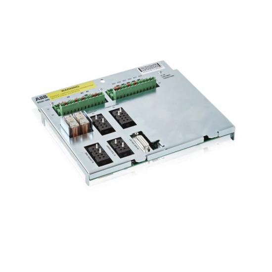
DSQC504 is a connector unit board in ABB industrial automation systems, which is a supporting hardware module for robots or controllers. It is mainly used for signal conversion and electrical connection management. Its core function is to provide standardized interface extensions for industrial control systems, enabling signal transmission and electrical adaptation between different devices, commonly found in robot controllers, PLC systems, or distributed I/O architectures.
Core features
Multi interface integrated design
Provide multiple electrical interfaces (such as terminal blocks and cable interfaces), supporting the access and distribution of digital signals (DI/DO) and analog signals (AI/AO).
Compatible with mainstream ABB controllers (such as IRC5 series), it can be combined with DSQC series I/O modules (such as DSQC346B, DSQC509) to build a complete automation control network.
High reliability connection
Adopting anti misconnection design (such as unique interface shape or coding) to avoid system failures caused by wiring errors.
The terminal supports high current loads (such as 24V DC, with a maximum current of 5A) and is suitable for driving actuators such as relays and solenoid valves.
Flexible system expansion
As an intermediate transfer layer, it can distribute the controller’s signals to multiple peripheral devices or aggregate multiple sensor signals to a single controller, simplifying wiring complexity.
Support hot swapping (some models) for easy system maintenance and upgrades, reducing downtime.
Industrial grade protection
Compliant with IP20 protection level, suitable for dust and slight splashing scenarios in industrial environments.
Anti electromagnetic interference (EMC) design ensures stable operation in strong electromagnetic environments, such as near frequency converters.
Typical application scenarios
Robot system integration
In industrial robot workstations, DSQC504 is used to connect robot controllers with end effectors (such as grippers and welding guns), transmitting control signals and feedback signals. For example:
Connect sensors (such as force sensors) to the controller to achieve force control feedback for robot operations.
Transfer the electromagnetic valve signal to control the opening and closing action of the pneumatic fixture.
Electrical cabinet for automated production line
As the signal center of the electrical cabinet in the production line, it distributes the control signals of the PLC to the executing equipment at each workstation (such as motor drivers and indicator lights), while collecting sensor signals (such as proximity switches and encoders) and transmitting them back to the PLC.
Typical scenario: In the automobile assembly line, the signals from the vehicle positioning sensor and the robotic arm controller are transferred to ensure assembly accuracy.
Process control equipment connection
In the control systems of the chemical and food industries, it is used to connect distributed I/O modules with field instruments (such as temperature transmitters and pressure switches) to achieve centralized processing of analog signals.
Support redundant connections (such as dual power inputs) to enhance the reliability of critical processes.
Testing and Development Platform
In laboratory or R&D scenarios, as a flexible signal testing interface, it facilitates engineers to access temporary sensors or debug equipment, accelerating system development and verification.
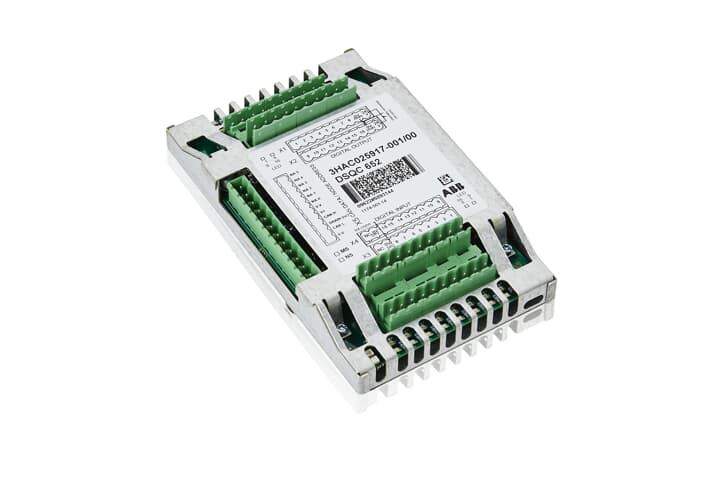
DSQC509 is a modular I/O module under ABB, suitable for the industrial automation field, and is a key component of robot controllers or industrial control systems. Its design focuses on high-precision signal processing and system integration flexibility, commonly used in scenarios such as robot arms, automated production lines, and process control equipment. It can achieve the acquisition, processing, and control output of digital/analog signals, supporting efficient collaboration with upper computers, sensors, and actuators.
Core functional characteristics
Multi type signal processing
Supports digital input/output (DI/DO): adapts to switch signals (such as button and relay status), with a response speed of milliseconds, used for logical control of equipment start stop, safety interlock, etc.
Supports analog input/output (AI/AO): can connect continuous signals such as temperature, pressure, current, etc. (such as 4-20mA, 0-10V), built-in high-precision ADC/DAC conversion module, with an accuracy of ± 0.1% FS.
Pulse signal processing: Supports encoder pulse counting, suitable for motor speed monitoring or position feedback.
Modularity and Scalability
Adopting standardized guide rail installation, supporting parallel combination of multiple modules, and expanding the number of I/O points (such as 16 point DI/16 point DO or 8-point AI/8-point AO configurations).
Compatible with mainstream ABB controllers such as IRC5 and AC800M, and enables fast data exchange through bus interfaces such as PROFIBUS DP and EtherCAT.
High reliability design
Electrical isolation: Optoelectronic isolation technology is used between channels, which has strong anti-interference ability and is suitable for strong electromagnetic environments (such as steel and chemical industries).
Fault diagnosis: Built in self diagnostic function, supports channel level fault detection (such as disconnection, short circuit), and provides real-time feedback on status (power supply, communication, fault) through LED indicator lights.
Wide temperature operation: The working temperature range is -20 ° C to+60 ° C, suitable for harsh industrial environments.
Communication and integration capabilities
Supports PROFIBUS DP V1 (maximum transmission rate of 12 Mbit/s), Ethernet/IP or Modbus TCP, seamlessly integrated into industrial Ethernet or fieldbus networks.
Support seamless integration with ABB robot systems (such as RobotStudio) to achieve collaborative control between robots and peripheral devices (such as fixture opening and closing, sensor triggering).
Typical technical parameters
Structural form: Modular (rail mounted)
I/O points: 16 digital quantities+8 analog quantities (expandable)
Used for signal control of end tools of industrial robots, such as welding guns and grippers, to achieve tool status feedback and action triggering.
Typical case: In the automotive welding production line, DSQC509 collects sensor signals to control the lifting of the welding gun and adjust the welding parameters.
Automatic production line
Connect conveyor belts, detection equipment, and actuators to achieve logical control of material sorting and assembly processes.
For example, in an electronic assembly line, the material arrival signal is monitored through digital input to drive the robotic arm to complete component picking and placement.
Process Control and Monitoring
In the chemical, food and beverage industries, it is used to monitor analog signals such as temperature and pressure, and output control instructions to regulate equipment such as valves and pumps.
Support integration with DCS (Distributed Control System) to achieve real-time closed-loop control of process parameters.
ABB DSQC346B is an advanced modular I/O system that plays a critical role in the field of industrial automation. It has become an ideal choice for many industrial enterprises to build efficient automation control systems due to its excellent performance, high flexibility, and outstanding reliability. This system can achieve precise acquisition and control of various industrial signals, effectively improving the automation level and stability of the production process.
Function characteristics
1. Diversified I/O interfaces
The DSQC346B is equipped with a wide range of I/O interfaces, including digital input/output and analog input/output interfaces. The digital interface can easily connect digital signal devices such as buttons and relays, quickly and accurately sensing device status and executing control instructions. For example, in an automated production line, it can quickly respond to various switch signals and control the start stop and operation of equipment. Analog interfaces are suitable for connecting sensors, industrial operation interfaces, etc. They can accurately convert received analog signals into digital values, meeting the collection and processing needs of continuous changing signals such as temperature, pressure, flow, etc. They are widely used in scenarios that require precise process control.
2. Efficient data processing capability
It has a powerful data processing core internally, capable of processing large amounts of I/O data at extremely high speeds. With a processing speed of up to 50MHz, the system can ensure timely response to various input signals in complex industrial environments and quickly generate accurate control outputs. Whether it is high-speed automated equipment or large-scale data collection tasks, it can handle them with ease, effectively improving the real-time performance and response speed of the entire control system.
3. Flexible module combinations
The system adopts a modular design concept, and users can freely choose different types and quantities of I/O modules to combine according to their actual application needs. This flexible configuration method enables the system to perfectly adapt to various complex and ever-changing industrial automation scenarios. Whether it is simple single machine automation control or large-scale factory automation production lines, the best control effect can be achieved through reasonable module combinations, while reducing system construction costs.
Reliable communication function
DSQC346B supports multiple communication protocols, such as PROFIBUS DP, Ethernet, etc. Among them, the PROFIBUS DP transmission rate can be extended to 12 Mbit/s, specifically optimized for interaction with remote I/O, drive, and motor control devices, ensuring fast and stable data transmission in industrial networks. Through Ethernet interface, the system can easily exchange and share data with the upper computer and other intelligent devices, achieving factory level information management and collaborative control, laying a solid foundation for building an intelligent factory.
Technical Parameter
Structural form: modular
LD instruction processor: hard PLC
I/O points: 3
Working voltage: 24V
Output frequency: 10/100 Mbps
Processing speed: 50MHz
Program capacity: 16MB
Data capacity: 256MB
Environmental temperature: 0 to 60 degrees Celsius
Environmental humidity: 5 to 95%, non condensing
Product certification: CE
Weight: 0.2 kilograms
Dimensions: 114mm, 257mm, 80mm
Application scenarios
1. Industrial automation production line
In industrial automation production lines such as automobile manufacturing and electronic equipment production, DSQC346B can collect real-time operation status signals of various equipment on the production line, such as equipment start stop, position detection, etc., and accurately control the operation of the equipment according to preset programs, realizing a series of automated operations such as material handling, processing, assembly, etc., effectively improving production efficiency and product quality, and reducing labor costs.
2. Process control field
In the process control industries such as chemical, power, and metallurgy, this system can accurately collect and control key process parameters such as temperature, pressure, and flow rate. For example, in chemical production, real-time monitoring and adjustment of temperature and pressure inside the reaction vessel ensure that the chemical reaction proceeds under optimal conditions, improve product yield and quality, and ensure the safe and stable operation of the production process.
3. Intelligent warehousing and logistics
In the intelligent warehousing and logistics system, DSQC346B can collaborate with automated three-dimensional warehouses, stackers, conveyors, and other equipment. By collecting information such as the location of goods and the operating status of equipment, automatic storage, retrieval, and handling of goods can be achieved, improving the operational efficiency of warehousing and logistics, and reducing errors during the storage and transportation of goods.
ABB 3HAB8859-1/03A is a high-performance control module designed specifically for industrial automation systems. It has precise control capabilities and can operate stably in complex industrial environments, providing reliable support for various industrial applications and occupying a key position in the process of industrial automation.
Brand background
ABB, as a globally renowned electrical and automation technology enterprise, has a history of over 130 years and operates in more than 100 countries, achieving excellence in various fields such as energy management, industrial automation, and motion control. It adheres to the concept of innovation, relies on profound technological accumulation and global service network, and continuously launches high-quality products. The 3HAB8859-1/03A module is the crystallization of ABB’s technological strength and innovative spirit.
Specification parameters
parameter
details
Input Voltage
Adapt to a wide voltage range, customized according to actual working conditions to ensure normal operation in different power environments
protection grade
Reaching IP20, dustproof, providing basic protection for internal circuits
size
Compact design, conducive to installation and integration in limited space, reducing equipment space occupation
weight
Lightweight, convenient for transportation and installation operations
communication interface
Equipped with multiple interfaces, such as RJ45 Ethernet ports for controlling network connections and supporting high-speed data transmission; Serial ports are used to connect configuration tools and adapt to different communication requirements
Core functions
Precise control signal output: Through precise engineering design, it can continuously and accurately output control signals, accurately regulate motor speed, equipment operating status, etc., improve the overall control accuracy and stability of the system, and meet the strict requirements for control accuracy in industrial scenarios.
Multi protocol compatibility: Compatible with multiple industrial automation protocols, such as common Modbus, Profibus, etc., facilitating integration in different automation system architectures, enabling data exchange and collaborative work with other devices and systems, enhancing system compatibility and scalability.
Real time monitoring and feedback: Real time monitoring of the working status and operating parameters of the controlled equipment, such as temperature, current, voltage, etc. Once the parameters are abnormal, they are quickly fed back to the control system, triggering corresponding protective actions or alarm prompts to ensure the safe operation of the equipment and reduce the risk of faults.
Working principle
This module is based on a built-in microprocessor and synchronizes system time accurately through a real-time clock. The microprocessor processes and analyzes the preset program and received external signals to generate control instructions. The instructions are transmitted to the corresponding output ports through the data bus and converted into driving signals to control external devices. For example, in the motor control scenario, the module receives a speed setting signal, and after internal algorithm calculation, outputs a PWM (Pulse Width Modulation) signal to adjust the motor speed. At the same time, it uses sensor feedback signals to adjust the control strategy in real time to ensure stable operation of the motor.
Key advantages
High reliability: The sturdy design can withstand harsh industrial environments such as high temperature, high humidity, strong electromagnetic interference, etc., ensuring long-term stable operation, reducing equipment failure downtime, and improving production efficiency.
Easy to integrate: Compact and lightweight, with design that fully considers integration requirements in terms of size, interface, communication protocol, etc., it can easily integrate into existing industrial automation systems without significant modifications, reducing system upgrade costs and difficulties.
Efficient and energy-saving: precise control functions prevent equipment from running excessively or idling, optimize energy utilization, achieve energy conservation and consumption reduction, conform to the trend of green industry development, and reduce enterprise operating costs.
Precautions
Installation environment: It should be installed in a dry, well ventilated, and temperature appropriate place, avoiding direct sunlight and strong corrosive gas environment to prevent module damage and affect performance and lifespan.
Electrical connection: Strictly follow the instructions for electrical connection, ensure that the wiring is firm and correct, prevent short circuits, open circuits and other problems, and ensure the normal operation of the module and the safety of personnel and equipment.
Software configuration: When configuring software parameters, professional personnel are required to operate and set them reasonably according to actual application needs to avoid abnormal device operation caused by parameter errors.
Similar model supplement
3HAB8101-19 DSQC545A: ABB’s high-performance servo drive focuses on the field of motor servo control, with stronger driving capabilities and more precise position control functions. It is suitable for industrial robots, CNC machine tools, and other equipment that require extremely high motor motion control accuracy and response speed.
PFSK164 3BSE021180R1: ABB signal concentrator board module, mainly used for signal centralized processing and transmission, plays a key role in large-scale data acquisition and monitoring systems, can efficiently integrate dispersed signals, achieve centralized management and transmission, and has different functional focuses from 3HAB8859-1/03A, but can work collaboratively in complex automation systems.
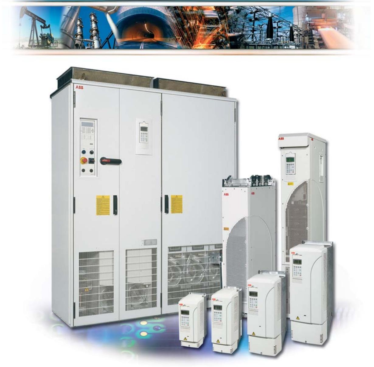
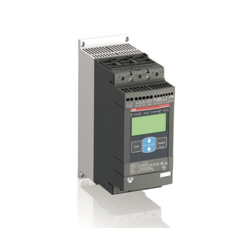
Scope of application: The firmware manual for the standard control program of ACS800 frequency converter is suitable for motor drive control in the field of industrial automation, supporting multiple control modes and communication protocols.
Core functions: including startup configuration, control panel operation, parameter setting, fault diagnosis, communication interface, and various application macros (such as factory macros, PID control macros, torque control macros, etc.).
Startup and control mode
Start the process
Startup Wizard: Guide users to complete motor parameter settings (such as voltage, current, frequency, etc.) and identification run (ID Run), supporting both standard and simplified identification modes to ensure motor control accuracy.
Basic startup: Manually input parameters, suitable for quick configuration scenarios without the need for a wizard.
control model
Local control: Directly operated through the control panel, supporting start, stop, steering, and speed settings.
External control: Receive commands through digital/analog inputs or fieldbus (such as PROFIBUS, Modbus), supporting dual control switching between EXT1 and EXT2.
Core functional modules
Program Function
Given signal processing: supports multi-source given signals such as analog input, digital input, fieldbus, etc., and can combine given signals through mathematical operations (such as addition, subtraction, multiplication, division, and taking the maximum value).
Torque control: Suitable for scenarios that require precise torque output, such as elevators and conveyor belts.
Braking control: Supports DC brake, magnetic flux brake, and mechanical brake, with configurable braking delay and torque threshold.
Application Macro Program
Factory macro: default mode, suitable for general speed control scenarios, supports 3 constant speed options.
PID control macro: used for process control (such as pressure and flow closed-loop), integrating sleep function to optimize energy consumption.
Torque control macro: directly controls motor torque, supports switching with speed control mode.
User macro: allows storage of two sets of custom parameters, facilitating quick switching between different motors or operating conditions.
Communication and Interface
Fieldbus support: compatible with protocols such as PROFIBUS, Modbus RTU/TCP, PROFINET, etc., and supports redundant communication configurations.
I/O expansion module: can connect digital/analog expansion modules, expand input and output channels, support motor temperature measurement, encoder interface, etc.
Parameters and actual signals
Parameter group division:
Startup data (99 sets): motor nameplate parameters, control mode, identification of operating configuration.
Given options (11 groups): Define the source of speed/torque given (such as analog input, fieldbus).
Limit values (20 sets): Setting operating limits such as speed, current, torque, etc.
Fault function (30 sets): Protection parameters for overcurrent, overvoltage, underload, etc., supporting automatic reset and alarm threshold setting.
Actual signal monitoring: Real time display of speed, current, torque, DC bus voltage, etc., supporting custom display combinations and filtering processing.
Fault diagnosis and maintenance
Fault codes and reset
Locate faults through control panel LED indicators or fault codes (such as overcurrent, overheating, communication interruption), and support manual or automatic reset (parameter configuration required).
Fault records store the last 6 events, including timestamps and fault types, to assist in quick troubleshooting.
Maintenance suggestions
Regularly check the matching of motor parameters, encoder connections, and the operating status of the cooling fan.
The communication module should pay attention to grounding and anti-interference, and avoid parallel wiring of high-voltage lines and signal lines.
Safety and Standards
Electrical safety: Ensure that grounding complies with NEC standards, avoid modifying parameters with motors, and prevent accidental start-up.
Electromagnetic compatibility (EMC): Sensor cables need to be shielded and grounded at one end, and isolated from high-voltage lines.
Compliance certification: Complies with IEC standards and supports explosion-proof applications in hazardous environments (requires corresponding module configuration).
Use MNavigate to re download the application to the CF card and ensure that the download process is interference free.
Network communication failure
1. Unable to access MLink() through web interface or MNavigate
Possible reasons:
IP address configuration error or network parameter conflict.
MLink is not powered on or there is a hardware malfunction (such as LED7 not lighting up).
The web server is not activated or the network link is interrupted.
resolvent:
Check the power and hardware status: Confirm that LED7 (power indicator light) is always on and there are no other fault LED alarms.
Verify network configuration:
Check whether the LAN2 IP address and subnet mask are correct through MNavigate (default: 192.168.200.100/24).
Use the ping command to test connectivity (such as ping 192.168.200.100), and if it fails, check the network cable connection or switch status.
Activate the web server: Confirm through MNavigate that the web service is enabled and restart MLink.
2. Communication with MControl failed (unable to download configuration) ()
Possible reasons:
The internal bus (Switchgear Bus) connection is loose or the terminal resistance is not configured.
MControl is not online or bus communication is interrupted (such as MControl’s LED flashing indicating offline).
resolvent:
Check physical connections: Ensure that the blue Sub-D 9-pin interface is secure, the bus cable shielding layer is well grounded, and the terminal resistance meets the topology requirements.
Activate MControl: Set MControl to “online” status through MNavigate and confirm that its LED status is normal.
Time synchronization failure
1. Inaccurate or missing timestamp ()
Possible reasons:
NTP server address error or network unreachable.
MLink internal RTC battery failure or no time synchronization mode configured.
resolvent:
Configure NTP server:
Set the correct NTP server IP address (such as 192.168.200. xxx) through MNavigate to ensure that it is on the same subnet as MLink.
If using MLink itself as an NTP server, it is necessary to manually set the time zone and time (through the web interface).
Check RTC function: Replace the CF card or contact technical support to confirm the status of the hardware RTC module.
Redundant system failure
1. Main/backup MLink synchronization failed ()
Possible reasons:
Redundant cables are not connected or damaged.
The configuration of the primary and backup modules is inconsistent (such as IP address conflicts).
resolvent:
Physical connection check: Confirm that the redundant cable (Serial 1 interface) is correctly connected and that the plugs at both ends are not loose.
Synchronous configuration: Generate redundant reports through MNavigate to ensure that the IP addresses and protocol parameters of the primary and backup modules are completely consistent.
CF card related faults
1. CF card cannot be recognized or configuration is lost ()
Possible reasons:
The CF card is not inserted correctly or has poor contact.
The card file is damaged (such as missing XML configuration file).
resolvent:
Re insert and unplug the CF card: Ensure that the card is oriented correctly (with the metal contacts facing upwards), and close the metal shield after insertion.
Rewrite configuration: Use a card reader to rewrite the configuration file generated by MNavigate to the CF card, avoiding interruptions in the download process.
General solution process
Restart MLink: Clear temporary software faults by pressing the front panel reset button or restarting after power failure.
Restore default settings: Use MNavigate to load factory default parameters such as IP address and subnet mask.
Hardware replacement test: If there is suspicion of hardware failure (such as continuous LED alarm), replace the CF card or MLink module and reconfigure.
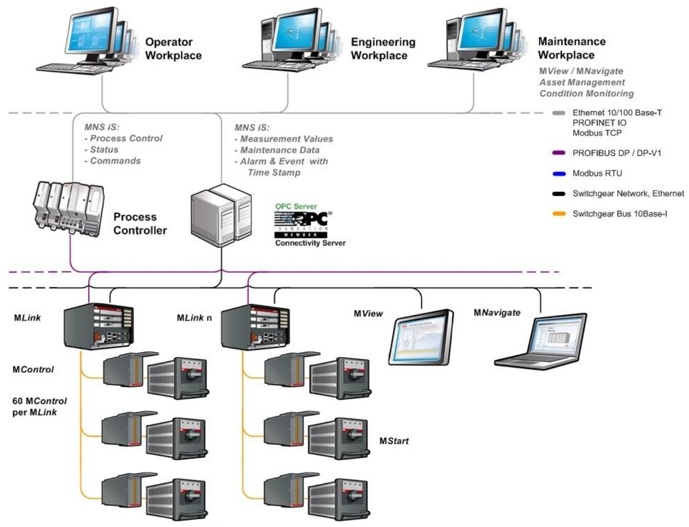
This document is the user manual (system version V7.0) for the MLink interface module (model 1TGE120021) in the ABB MNS iS system. It mainly introduces its hardware features, software modules, communication interfaces, and operation and maintenance. The following is a detailed summary:
Product positioning and target users
Positioning: MLink is an industrial PC module that serves as the core communication interface for MNS iS systems, connecting internal motor control units (MControl) and external control systems (such as DCS, PLC), supporting data exchange, status monitoring, and system integration.
Target users: System engineers, control engineers, familiar with fieldbus (such as PROFIBUS, Modbus) and industrial communication basics.
Power supply: 24V DC (19-31V DC), typical power consumption 800mA
Size: 140 × 160 × 165mm, weight 2.5kg
Working temperature: 0 ° C~55 ° C, protection level IP51
Mean Time Between Failures (MTBF): 46 years (40 ° C environment)
2. Interface and Connection
Front board interface:
Internal communication: Blue Sub-D 9-pin interface (Switchgear Bus), connected to MControl, supports redundant configuration.
External communication:
PROFIBUS DP: Black interface with communication status LED (yellow running, green ready).
Modbus RTU: RS485 interface (Serial 2).
Ethernet (LAN1/LAN2): LAN1 is used for Modbus TCP or PROFINET, while LAN2 connects to the control network (10/100 Base-T).
Other interfaces: reset button, CF card slot (supporting hot swappable protection), power terminal (+24V/GND).
Software modules and functions
Core module:
Web Server: Access the MView interface through a browser to monitor system status (activation required).
OPC Server: Supports data acquisition (DA) and alarm events (AE), requiring separate software installation.
Fieldbus module: Implement protocol conversion with DCS, depending on hardware model (such as PROFIBUS/Modbus).
Time synchronization: Supports NTP protocol and can provide timestamps through GPS or internal RTC to ensure event recording accuracy.
Redundancy support: Dual MLink modules are synchronized through redundant cables, with primary and backup switching to ensure system reliability.
Communication network configuration
1. Internal network (Switchgear Bus)
Function: Connect MLink and MControl (up to 60), the cable shielding layer needs to be grounded at both ends, and supports bus topology and terminal resistance configuration.
Features: Plug and play, no additional configuration required, communication status monitored through LED (Swg Bus Rx/Tx).
2. Switchgear Control Network
Architecture: Based on standard Ethernet (LAN2), supporting direct connection (cross cable) or connecting multiple MLinks, MView (human-machine interface), and engineering tools (MNavigate) through switches.
Security requirements: If you need to access the factory network, you need to configure a firewall and router to prevent unauthorized access.
Time synchronization scheme:
Option 1: Third party NTP servers (such as switches with GPS) provide time signals.
Option 2: MLink acts as an NTP server to synchronize time with other devices (with a built-in RTC that can cache for 3 hours).
Operation and maintenance
1. Initial setup
Tool: Use MNavigate software to configure parameters such as IP address, subnet mask, time server, etc. The parameters need to be written to the CF card and restarted to take effect.
Default value:
LAN2 IP:192.168.200.100,LAN1 IP:192.168.100.100
DHCP is not supported, network parameters need to be manually configured.
2. Installation steps
Physical installation: Installed in the control cable compartment of the MNS iS cabinet, fixed with metal brackets and supporting quick insertion and removal.
CF card operation: When inserting, pay attention to the direction (mechanical coding to prevent reverse insertion), and the configuration file needs to be written through MNavigate.
3. Fault diagnosis
LED indicator light: It displays the operating status, communication faults, and redundancy status through 8 LEDs (such as LED2 indicating system faults and LED6 indicating DCS communication activation).
Common problem handling:
Network failure: Check IP configuration, ping test connectivity, and rewrite CF card configuration.
MControl offline: Confirm internal bus connection and MControl online status settings.
Documentation and Compatibility
Related documents: The accompanying manual covers the web interface PROFIBUS、Modbus、 Special content such as redundant configuration.
System compatibility: Only applicable to MNS iS System Release 7.0, please refer to the latest system guidelines for functional implementation.
Summarize
The MLink module is the communication hub of ABB MNS iS system, which seamlessly integrates motor control with upper level systems in industrial environments through flexible protocol support and reliable hardware design. Its core advantages include multi protocol compatibility, high time synchronization accuracy, and strong redundancy reliability, making it suitable for automation control systems that require high real-time performance and stability. Operation and maintenance rely on the specialized tool MNavigate, and attention should be paid to network configuration specifications and hardware installation details.
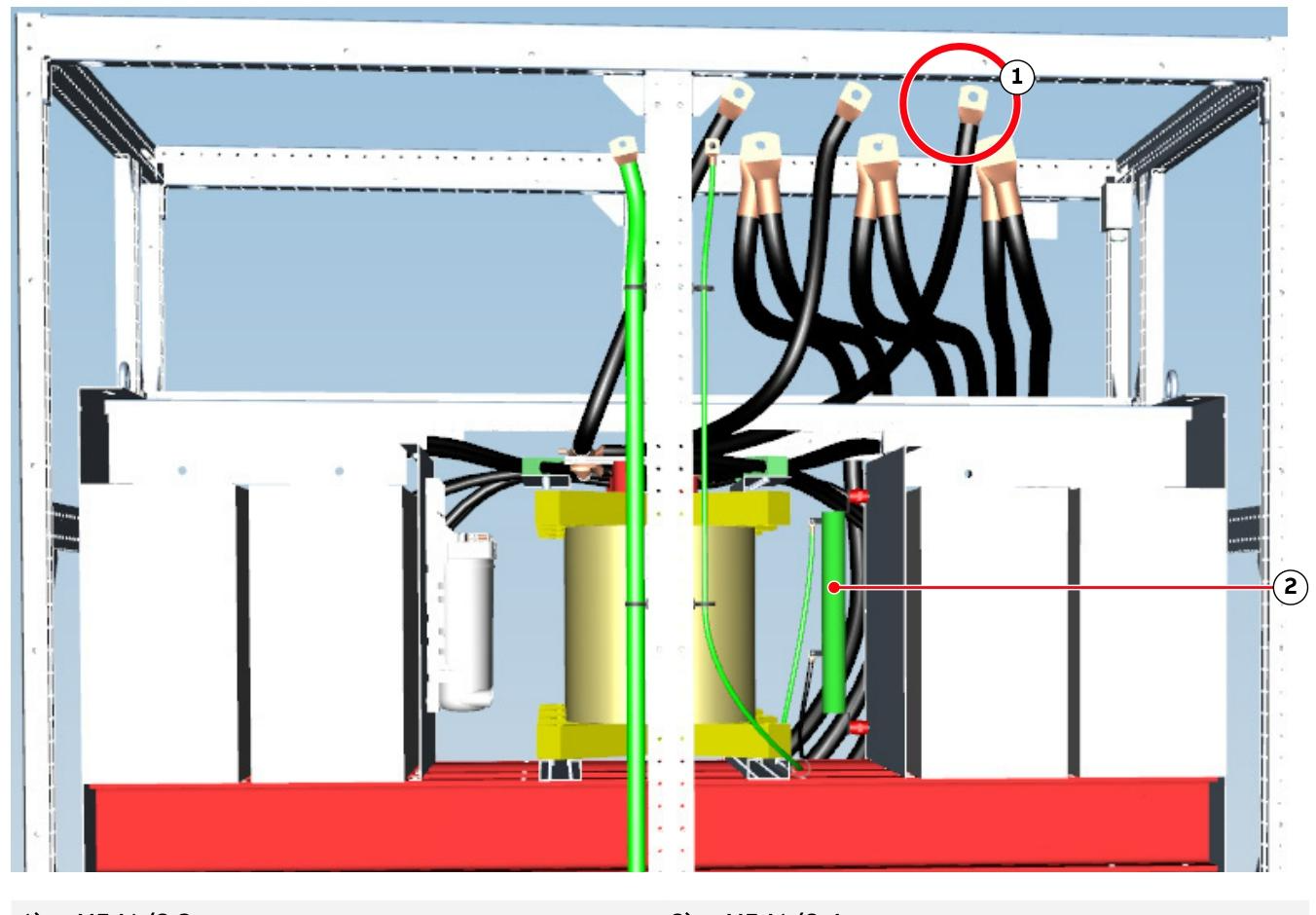
Strictly follow the “Seven Step Life Saving Rule”, including risk assessment, power outage lockout (LOTO), voltage detection, grounding short circuit and other processes, to ensure operational safety.
The equipment poses risks of high voltage, high temperature, and electromagnetic fields. Maintenance personnel need to wear protective equipment to avoid contact with live parts and high-temperature surfaces.
Residual risks include electromagnetic interference with pacemakers, accidental movement, contact voltage, etc. It is necessary to ensure that the equipment operates within the specified parameter range.
special tools
Converter service toolbox: includes expansion tools for disassembling semiconductor stacks, stabilizing boards, etc., used to release stack pressure and replace components.
Debugging tools: such as RCI Box XU D194 (signal monitoring), PCS6000 HMI (human-machine interface), FADEC 3 (semiconductor testing equipment).
Replacement tools: including foundation beam jacks, chain hoists, pump maintenance platform kits, etc., used for dismantling and installing heavy components.
Preventive maintenance
Maintenance cycle and tasks
Daily/quarterly: visually inspect for dust and signs of overheating, clean cabinets, check bolt tightness and cable wear.
Year: Test the tripping circuit, insulation resistance, and grounding resistance of the main circuit breaker (MCB), and replace aging components such as batteries and fans.
Specific inspection:
Semiconductor stacking: Use FADEC 3 to detect IGCT and diodes, check stack alignment and clamping force.
Cooling system: Check the conductivity of the coolant, replace the ion exchange resin and filter, and inspect the function of the pump and valve.
Filter components: measure resistance and capacitance values to verify filtering performance.
Maintain records
Use the Preventive Maintenance Report to record component replacements, parameter adjustments, and abnormal situations to ensure traceability.
Component replacement and repair
1. Replacement of control components
AC 800PEC controller: Replace after power failure, pay attention to firmware version matching, and verify LED status after reconnecting the cable.
UPS and battery: When replacing, power off and release residual voltage. Pay attention to matching battery polarity and model, and test the charging and discharging function.
Fiber optic cable: Cut and polish with specialized tools to ensure that the connection loss meets the standard and avoid contaminating the fiber optic end face.
2. Replacement of power and cooling components
IGCT and diode:
Release the stacking pressure, use the expansion tool to separate the heat sink, replace it, realign the stack and tighten it.
Check the polarity and clean the contact surface, avoid using grease, and ensure even clamping force.
Cooling system components:
Pump: Drain the coolant, remove the flange and electrical connections, replace with a dedicated bracket, pay attention to the direction and sealing of the impeller.
Ion exchanger and filter: After replacement, the system needs to be flushed to test flow rate and conductivity.
Valves and sensors: After replacement, pressure and temperature sensors need to be calibrated to ensure that the control system is functioning properly.
3. Module level replacement
Voltage Limiting Module (VLM): After power failure, remove the cables and cooling pipelines, replace them, and test the voltage relief function.
Grid Circuit Breaker Unit (GBU): Use a dedicated trolley to disassemble the circuit breaker, check the wear of the contacts, reinstall and test the opening and closing time.
Dv/dt filter: When replacing reactors, resistors, and capacitors, it is necessary to match the model and parameters to ensure EMI suppression performance.
4、 Troubleshooting process
diagnostic procedure
Read the fault code through HMI or debugging tools, analyze the first fault (FF) and related alarms, check the LED status and historical records.
Check the power supply, communication links, sensors, and semiconductor components, and use tools such as multimeters and oscilloscopes to measure voltage and resistance values.
Typical fault handling
IGCT fault: Conduct characteristic detection through FADEC 3, replace and recalibrate trigger signal.
Cooling system leakage: locate the leakage point, replace the seals or pipelines, and test whether the pressure and flow are normal.
Communication interruption: Check the fiber optic connection, module power supply, and address settings, and replace the faulty S800 I/O module or communication board.
5、 Special precautions
Static Electricity Protection (ESD)
When operating the control board and semiconductor, it is necessary to wear a grounding wristband and use anti-static pads to avoid direct contact with circuit contacts.
Heavy component operation
Components weighing over 25 kg, such as reactors and circuit breakers, require the use of lifting tools, with two people working together to avoid the risk of falling.
Documentation and Compliance
Replacing serialized components (such as IGCT and capacitors) requires updating the ABB database and recording the new serial number.
Follow environmental requirements, dispose of waste components (such as batteries and circuit boards) correctly, and avoid environmental pollution.
The relevant models and component models of ABB PCS6000 are as follows:
Main device model
PCS6000
The medium voltage frequency converter models covered by the core of the manual are suitable for industrial scenarios such as large wind turbines and tidal energy, and support 1CL (single conversion line) and 2CL (dual conversion line) configurations.
Core component model
1. Power Unit (POU)
IGCT model:
5SHY 3545L0016 (old generation)
5SHY 4045L0006 (new generation, can replace old models one-on-one)
DC capacitor:
DCMKP 2.6kV/2×1.5mF(3BHB006617R0013)
DCMKP 3.15kV/2×1.01mF(3BHB006617R0014)
2. DC Link Unit (DLU)
Neutral Connection Module (NCM):
Includes resistors – R461, – R462_1/- R462_2, and capacitor – C461.
Voltage Limiting Module (VLM):
VLM30 (weighing approximately 50kg), VLM70 (weighing approximately 60kg).
Dv/dt filtering module (VFM):
Reactors, resistors, and capacitors components (such as – R581 to – R586, – C581 to – C587).
3. Grid Circuit Breaker Unit (GBU)
Circuit breaker model:
GEB (Generator Circuit Breaker), GRI (Grid Circuit Breaker), weighing approximately 160kg, compatible with VD4 series.
Dv/dt filter component:
Reactors, resistors, capacitors (such as – R581 to – R586, – C581 in GBU).
4. Water cooling unit (WCU)
Pump model:
Sweden water series: such as 300l/min pump (3BHE038551R0001, weight 77kg), 565l/min pump (3BHE043674R0001, weight 90kg).
ARMATEC series: Please refer to the accompanying service manual (such as Appendix B06).
Ion exchanger: For resin model adaptation, please refer to Safety Data Sheet (SDS) 81000-193.
5. Filter Unit (FIU)
High pass filtering module (HFM):
Reactors (such as 3BHE035425R0001, weighing 25kg) and capacitors (- C541 to – C544, weighing 41kg).
Filter Reactor Module (FRM):
For FRM70 (weighing 900kg), a dedicated replacement kit (3BHE039651R0001) is required.
6. Braking resistor unit (BRU)
model:
BRU50 (200kg), BRU51 (235kg), BRU70 (400kg), etc., suitable for different power requirements.
Adhere to standards: The manual strictly follows international standards such as ANSI Z535.6 (Safety Information Standard), ISO 3864-2 (Safety Label Design), EN 50110 (Electrical Safety Code), etc., to ensure the safety of equipment during design, installation, and operation.
Warning label classification:
DANGER: Refers to a dangerous situation that, if not avoided, could result in death or serious injury (such as high-voltage electric shock).
Warning: Potential risk of serious injury or equipment damage (such as high temperature surfaces, mechanical compression).
CAUTION: Possible situations that may cause minor injury or equipment malfunction (such as electrostatic discharge, misoperation).
Notice: Non safety related but important operating precautions (such as dust accumulation affecting equipment performance).
Special warning: The electromagnetic field generated during equipment operation may interfere with pacemakers. Warning signs should be marked near the equipment to restrict access by relevant personnel.
2. Seven step safety operation process
To prevent electric shock and arc damage during electrical operations, the manual defines a strict “seven step life-saving principle”:
Homework preparation: Conduct on-site risk assessment, confirm work permit, and equip appropriate personal protective equipment (PPE, such as insulated gloves and arc protective clothing).
Equipment identification: Confirm the equipment status through visual and auditory inspection, set up physical isolation barriers to avoid interference from unrelated personnel.
Power off locking (LOTO): Disconnect all energy supplies, use locks and labels to prevent accidental closing, and implement group LOTO for multi person operations.
Voltage detection: Use qualified voltage detection equipment to verify that there is no voltage after power failure, and calibrate the equipment on a known power source before and after the detection.
Grounding and short circuit: Close the grounding switch or use a portable grounding device to ensure safe discharge of fault current.
Protection of adjacent live parts: Maintain a safe distance, use insulated shielding tools, and avoid contact with exposed conductors.
License confirmation: Check the isolation points and grounding status to ensure that all operators understand the risks before signing the license document.
3. Safety requirements for main circuit breakers (MCBs)
Functional positioning: MCB is the core protection device of the frequency converter, which needs to quickly cut off the main power supply in case of a fault to prevent personnel injury and equipment damage.
Technical parameters:
Breaking time: Protection tripping time ≤ 75 ms (to limit equipment damage), safety tripping time ≤ 500 ms (to ensure personnel safety).
Control mode: The MCB disconnection command needs to come directly from the frequency converter. If it is transferred through PLC/DCS, the system needs to pass SIL 3 certification, and the use of local remote switch interruption disconnection commands is prohibited.
Redundant design: It is recommended to equip with dual independent trip coils or undervoltage coils, combined with the “Circuit Breaker Failure Protection (ANSI 50BF)” function of the upstream circuit breaker, to ensure reliable disconnection in case of a fault.
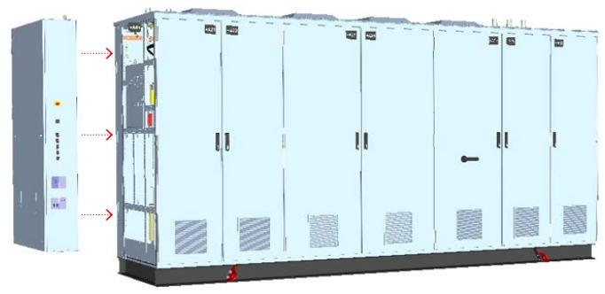
Product Architecture and Modular Design
1. Application scenarios and configuration selection
Core application: PCS6000 is a medium voltage frequency converter (3.3 kV level) designed specifically for large wind turbines and tidal energy equipment, supporting full power conversion and suitable for grid connected and off grid applications.
Topology structure:
1CL (single conversion line): Compact structure, suitable for conventional working conditions.
2CL (Dual Conversion Line): Supports “Restricted Mode”, which allows for single line operation when one line fails, improving system availability and reducing downtime.
2. Detailed explanation of modular components
(1) Power Unit (POU)
Function: Implement AC-DC-AC conversion of electrical energy, including three 3-level neutral point clamp (NPC) phase bridge arms, using integrated gate commutated thyristors (IGCT), supporting high voltage and high current operating conditions.
Design features:
Semiconductor devices are integrated into a single stacked structure to improve heat dissipation efficiency.
The main circuit interface board is responsible for controlling signal processing and status monitoring, and supports real-time fault diagnosis.
(2) DC Link Unit (DLU)
Core module:
Neutral Connection Module (NCM): Grounding the neutral point through an RC network, limiting the rate of change in ground voltage (dv/dt), allowing for short-term operation under single ground faults, and rapid shutdown after fault detection.
Voltage limiting module (VLM): When the DC link voltage exceeds the threshold, energy is released through the braking resistor, and the capacitor is discharged during shutdown to ensure maintenance safety.
Dv/dt filtering module (VFM): suppresses high-frequency oscillations generated by IGCT switches, protects transformer and generator windings, and reduces electromagnetic interference (EMI).
Generator Isolation Switch Module (GDM): Three position electric isolation switch (closed/open/grounded), supports manual operation (equipped with a rotating handle), isolates the generator in case of a fault.
(3) Grid Circuit Breaker Unit (GBU)
Function integration:
Circuit breaker: It realizes the on/off and short-circuit protection of the grid side circuit, and supports vacuum circuit breakers or SF ₆ circuit breakers.
Three position switch: including “connection”, “test”, and “grounding” positions. When grounding, it is necessary to operate under zero current to ensure personnel safety.
Operation method: Manually operated by hand crank, equipped with mechanical interlocking to prevent misoperation.
(4) Other key units
Water cooling unit (WCU): maintains constant water temperature (≥ 0 ° C) and flow rate, supports external heat exchanger connection, built-in ion exchanger purifies cooling medium, and pump set supports soft start to reduce impact.
Filter Unit (FIU): It includes a High Pass Filter Module (HFM) and a Filter Reactor Module (FRM), which meet the harmonic limit standards of the power grid (such as IEC 61000-3-6).
Braking Resistance Unit (BRU): Modular design, supports roof installation, maximum cable length of 10 meters, monitors heat dissipation through temperature models, optional BRU51/52/72 models, thermal capacity 7.5-15 MJ.
3. Cabinet design and protection
Mechanical structure:
Galvanized steel frame+1.5mm powder coated steel plate, protection level IP54, resistant to dust and water spray.
Modular design supports back-to-back and series layout, saving installation space and suitable for narrow environments such as wind turbine cabins.
Electromagnetic compatibility (EMC):
The cabinet doors and side panels are sealed with conductive gaskets, and the internal panels are not painted to enhance the metal grounding effect.
The cable entry is equipped with EMC shielding strips to ensure that radio frequency interference (RFI) suppression complies with EN 61000-6-4 standard.
Environmental adaptability:
Working temperature: -10 ° C~+40 ° C (when the water cooling system is running), storage temperature: -25 ° C~+55 ° C.
Vibration protection: Compliant with IEC 60068-2-6 standard, suitable for the vibration environment of wind turbines.
Installation and commissioning process
1. Transportation and Storage Standards
Packaging requirements:
Land transportation: Wooden pallets (thickness 5 cm, length and width exceeding the cabinet by 30/60 cm)+polyethylene film (0.12 mm thickness), fixed with a winding machine applying 20-38 units of tension.
Sea freight: wooden box+aluminum foil moisture-proof film (three-layer structure, middle layer aluminum foil isolates water vapor), desiccant (in accordance with DIN 55474) placed inside, humidity indicator monitors environmental humidity.
Precautions for handling:
Using a crane or forklift, it is prohibited to directly lift the top of the cabinet, and force must be applied through the bottom lifting ring.
The fork distance of the forklift should be greater than 1500 mm, and the driving speed should be limited to walking speed to avoid tilting more than 30 degrees.
2. Mechanical and electrical installation
(1) Mechanical installation
Basic requirements: The cabinet is fixed to the horizontal floor with M16 bolts, and the bottom sealing plate can serve as a water collection tray to prevent internal water leakage from spreading.
Environmental control: The installation area should be dust-free, and the equipment should be covered with plastic sheeting during construction to prevent dust from entering; Paint damage needs to be repaired with polyurethane coating to ensure anti-corrosion and insulation performance.
(2) Electrical installation
EMC cabling principles:
Cable classification:
Class 1: Sensitive signals (such as 4-20 mA analog signals) require twisted pair shielding, with both ends of the shielding layer grounded.
Class 4: High interference lines (such as motor start stop signals), with a distance of ≥ 600 mm from other cables, laid vertically when crossing.
Shielding grounding: The shielding layer of the power cable needs to be connected to the grounding busbar near the frequency converter. If the cross-sectional area of the shielding layer is less than 50% of the phase conductor, equipotential bonding wires need to be laid in parallel.
High voltage connection:
Using Pfister ® PLUG P3 series connectors (such as P3SC straight type, P3EC1/2 curved type), code AF01 to ensure correct pairing, cable cross-sectional area of 70-240 mm ², maximum length of 150 m (grid side)/100 m (generator side).
When connecting, ensure that the plug is aligned with the socket and the torque meets the manufacturer’s requirements to avoid overheating caused by poor contact.
(3) Grounding system
Protective grounding (PE): The cabinet is connected to the main grounding grid through bottom M12 bolts, and the cross-sectional area of the grounding conductor is ≥ 95 mm ² (calculated based on a fault current of 16.2 kA and a breaking time of 0.5 seconds).
Functional grounding (FE): Used to discharge the common mode current generated by switch devices, separated from PE, and connected through an independent grounding bar to ensure EMC performance.
3. Debugging and Startup
prerequisite:
Complete mechanical alignment, bolt tightening, and cooling system water injection (deionized water+ethylene glycol).
The electrical connection is correct and the insulation test is qualified (the insulation resistance of cables, transformers, and generators meets the specifications).
Anti exposure activation sequence:
When the device is powered off for a long time and restarted, the control unit heater needs to be started first. When the internal temperature is ≥ 5 ° C and there is no condensation, the water-cooled pump is started for circulating heating. The entire process may last for 12 hours (in a low-temperature environment).
Pre startup inspection:
Confirm that all cabinet doors are closed, door lock switches are functioning properly, and there are no fault alarms (such as when the DC link grounding switch is in the “ungrounded” position and the LED indicator light is off).
Set the key switch to “ON”, the auxiliary power supply (3AC 400V/24VDC) is supplying power normally, and the pressure and flow rate of the water cooling system meet the standards.
Operation and Maintenance Guide
1. Daily operation interface
Local control device (located on the side of CCU):
Emergency stop button: Immediately disconnect the MCB after pressing, block the IGCT pulse, discharge the DC link through VLM, manually reset and clear the fault before recovery.
Key switch: controls the “start disable” or “local/remote” mode switching to prevent unauthorized operation.
Status indicator light: displays grid/generator voltage, grounding status, DC link status, etc. For example, if the “ISOLATOR CLOSED” light is on, it indicates that the DC link has been grounded and can be safely maintained.
Remote control: Connected to the higher-level control system through fieldbus (such as Profibus, Ethernet), supporting real-time monitoring of parameters such as voltage, current, temperature, etc., receiving start stop commands and fault alarms.
2. Maintenance strategy and cycle
Preventive Maintenance Plan (Refer to PCS6000 Preventive Maintenance Plan 3BHS600000 E88):
Daily: Check the operating status, cooling system leaks, and whether there are any abnormal noises or odors.
Quarter: Clean the dust inside the cabinet (blow with compressed air, avoid using damp cloth), check the tightness of bolts and cable wear.
Year: Test MCB trip circuit, insulation resistance, grounding resistance, replace aging components (such as capacitors and fans), and record maintenance logs.
Key maintenance tasks:
Water cooling system: Replace ion exchange resin annually, check the conductivity of the coolant (≤ 5 μ S/cm), and clean the surface dirt of the heat exchanger.
IGCT inspection: Dynamic testing is conducted every two years to confirm that the switch characteristics meet the factory standards and avoid faults caused by device aging.
3. Fault diagnosis and handling
Fault classification:
Alarm: Do not interrupt operation. If the cooling water temperature is too high or the fan fails, the cause should be promptly investigated.
Fault: Forced shutdown, such as overvoltage, short circuit, IGCT fault, should be reset and repaired according to the “Fault Manual” (Appendix A09).
Processing procedure:
Record fault code: Obtain fault information through remote interface or local display screen, such as “F001: DC Link Overvoltage”.
Preliminary investigation: Check the power supply voltage, brake resistor connection, VLM function, and confirm whether it is caused by power grid fluctuations or sudden load changes.
Professional maintenance: If it is a hardware failure (such as capacitor rupture, IGCT damage), ABB authorized personnel must replace the components. Non professionals are prohibited from disassembling high-voltage components.
Spare parts management: Key spare parts (such as IGCT and control board) need to be stored in anti-static packaging, with a storage environment temperature of 5 ° C~40 ° C and humidity ≤ 60%.
Documentation and Compliance
1. Supporting documents
Manual and drawings:
PCS6000 Service Manual (3BHS600000 E80): Detailed disassembly steps and component replacement guide.
EMC and Grounding Plan (3BHS856856 E62): Guide cable layout and grounding system design.
Electrical Drawings (Appendix A03): Includes schematic diagrams, wiring diagrams, and terminal block definitions.
Electronic documents: USB storage devices are provided with the device, including interface files, firmware upgrade programs, and fault diagnosis tools.
2. Compliance and Certification
Safety certification: CE certification (compliant with Low Voltage Directive, EMC Directive), some markets require UL/cUL, T Ü V and other certifications.
Standard compliance:
EMC: The emission limit complies with EN 61000-6-4, and the immunity complies with EN 61000-6-2.
The ABB PCS6000 user manual focuses on safety and ensures the reliable operation of medium voltage inverters in the field of renewable energy through modular design, strict installation procedures, and full lifecycle maintenance strategies. Users need to strictly follow the safety regulations in the manual, combined with professional training and regular maintenance, to maximize the energy efficiency and service life of the equipment. If further support is needed, technical support and spare parts supply can be obtained through ABB’s global service network.
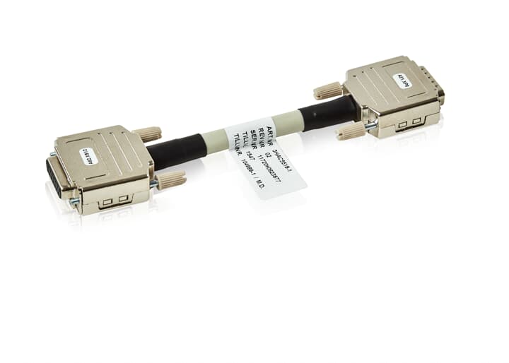
ABB 3HAC5518-1 Industrial Control Module is a professional equipment that focuses on the efficient and precise control needs of industrial automation. It undertakes the core functions of data processing, logical operation, and equipment collaborative control in complex industrial scenarios. It can quickly respond to signals collected by various sensors, accurately output control instructions according to preset programs, drive actuators to complete complex tasks, and is a key component to ensure stable and efficient operation of industrial production processes. It is widely used in automation upgrade projects in multiple fields such as manufacturing, energy, and logistics.
Brand background
ABB, as a leading global enterprise in the fields of power and automation technology, has set an industry benchmark in industrial automation with over 130 years of technological accumulation and innovative practices. Its profound research and development background, strict quality control system, and global service network ensure that products are always at the forefront of technology. The 3HAC5518-1 industrial control module inherits ABB’s consistent high-quality standards, integrates advanced technology and industry experience, and provides users with reliable automation control solutions.
Specification parameters
working voltage
Supports 24V DC wide voltage input, can adapt to a certain range of voltage fluctuations, ensuring stable operation in complex industrial power supply environments
communication interface
Equipped with Ethernet interfaces (supporting Profinet, Ethernet/IP protocols), RS-485, CAN bus, etc., to achieve seamless communication among multiple devices
I/O channel configuration
12 digital input channels, 10 digital output channels, 6 analog input channels, 4 analog output channels, suitable for diverse control scenarios
Working temperature range
-From 20 ℃ to+60 ℃, it can work continuously and stably in harsh industrial environments such as high and low temperatures
protection grade
IP20, Capable of basic dust prevention, effectively preventing objects with a diameter greater than 12mm from entering and protecting internal circuits
Certification standards
Through international authoritative certifications such as CE and UL, we comply with global industrial safety and quality standards to ensure product reliability
Core functions
High precision control: Equipped with advanced PID, fuzzy control and other algorithms, the adjustment accuracy of parameters such as motor speed, valve opening, temperature and pressure can reach ± 0.1%, meeting the high demand for control accuracy in precision manufacturing, semiconductor production and other scenarios.
Multi device collaborative management: With rich communication interfaces and strong protocol compatibility, it can simultaneously connect multiple devices such as robotic arms, conveyor belts, and detection instruments, accurately coordinate equipment working timing and actions, and improve the overall efficiency of automated production lines.
Real time data processing: It has the ability of high-speed data acquisition and edge computing, can filter, analyze and store sensor data in real time, optimize production process in advance through data trend prediction, and prevent equipment failures.
Intelligent fault diagnosis: Built in fault diagnosis system, real-time monitoring of module and connected device operation status. When communication interruption, overload, abnormal data and other faults occur, sound and light alarms are immediately triggered and detailed fault information is uploaded to assist technical personnel in quickly locating and troubleshooting.
Working principle
When the 3HAC5518-1 is working, the input channel first receives analog or digital signals from temperature, pressure, position and other sensors. After the analog signals are converted into digital signals through the A/D converter, they are transmitted to the internal processor together with the direct input digital signals. The processor performs logical operations and analysis on data based on preset control programs and algorithms, determines the production process status, and generates corresponding control instructions. The instructions are sent to actuators such as motors, solenoid valves, and regulating valves through D/A converters (for analog outputs) or digital output channels to drive the equipment to perform actions. The communication module is responsible for exchanging data with the upper computer, other control modules, and devices, uploading operational data, and receiving parameter adjustment instructions; The fault diagnosis module continuously monitors the status of various parts of the system, and promptly activates the alarm and handling mechanism in case of abnormalities to ensure the stable operation of the system.
Key advantages
High reliability and stability: Using high-quality components and redundant design, after rigorous aging, high and low temperature, and vibration testing, the mean time between failures (MTBF) exceeds 100000 hours, and it can still operate stably in harsh environments such as strong electromagnetic interference and high dust.
Flexibility and Scalability: The modular structure supports on-demand configuration of I/O channels and functional modules, facilitating system upgrades and renovations; Support hot swapping function, modules can be replaced during device operation, reducing maintenance downtime.
Convenient and easy-to-use: Supports multiple programming languages such as ladder diagrams and structured text, making it easy for engineers to program and debug; Equipped with intuitive graphical user interface and configuration software, reducing operational learning costs and improving debugging efficiency.
Wide compatibility: Not only seamlessly integrated with other ABB industrial equipment, but also compatible with mainstream third-party brand equipment, making it easy for users to build personalized industrial automation solutions.
Precautions
Installation environment: Choose a dry, ventilated and away from strong electromagnetic interference sources for installation, avoid high temperature, humidity, corrosive gases or high dust places, and ensure that the environmental temperature and humidity are within the working range.
Wiring operation: strictly follow the product manual for wiring, distinguish the positive and negative poles of the power supply from the input and output signal lines, and prevent misconnection; Different types of signal lines are wired separately, and the grounding wire is reliably grounded and the resistance meets the requirements.
Parameter setting: Before use, configure the software to accurately set communication protocol, baud rate, device address, I/O type and other parameters based on the actual application scenario, and conduct functional testing.
Regular maintenance: Regularly check the appearance of the module, the tightness of the wiring terminals, and the operation status of the cooling fan; Clean the dust on the surface of the module, calibrate the performance according to the prescribed cycle, and ensure control accuracy.
Similar model supplement
ABB 3HAC5518-2 Industrial Control Module: Compared to 3HAC5518-1, this model increases the number of analog input channels and reduces the number of digital output channels, making it more suitable for monitoring scenarios such as chemical and energy industries that require large amounts of analog signals such as temperature and pressure.
ABB 3HAC5519-1 Industrial Control Module: Upgraded in data processing and communication performance, equipped with higher performance processors, faster data processing speed, support for more industrial communication protocols and higher transmission rates, suitable for systems with extremely high real-time requirements such as central control in smart factories and large-scale power dispatch.
Application scenarios
Manufacturing industry: controlling robot welding and assembly in automobile manufacturing; Manage SMT surface mount machines and semiconductor packaging equipment in electronic manufacturing to improve production accuracy and efficiency.
Energy industry: monitoring and controlling generator parameters in thermal power plants; Regulating power generation equipment in wind and solar power plants to ensure stable energy production and efficient conversion.
Transportation: control signal timing and monitor road equipment in the intelligent transportation system; Control train signals and platform screen door systems in rail transit to ensure transportation safety.
Food and medicine: precise control of process parameters such as temperature and pressure in food processing; Ensure the accuracy of equipment operation and sterile environment in pharmaceutical production, and guarantee product quality and safety.