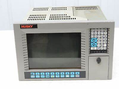
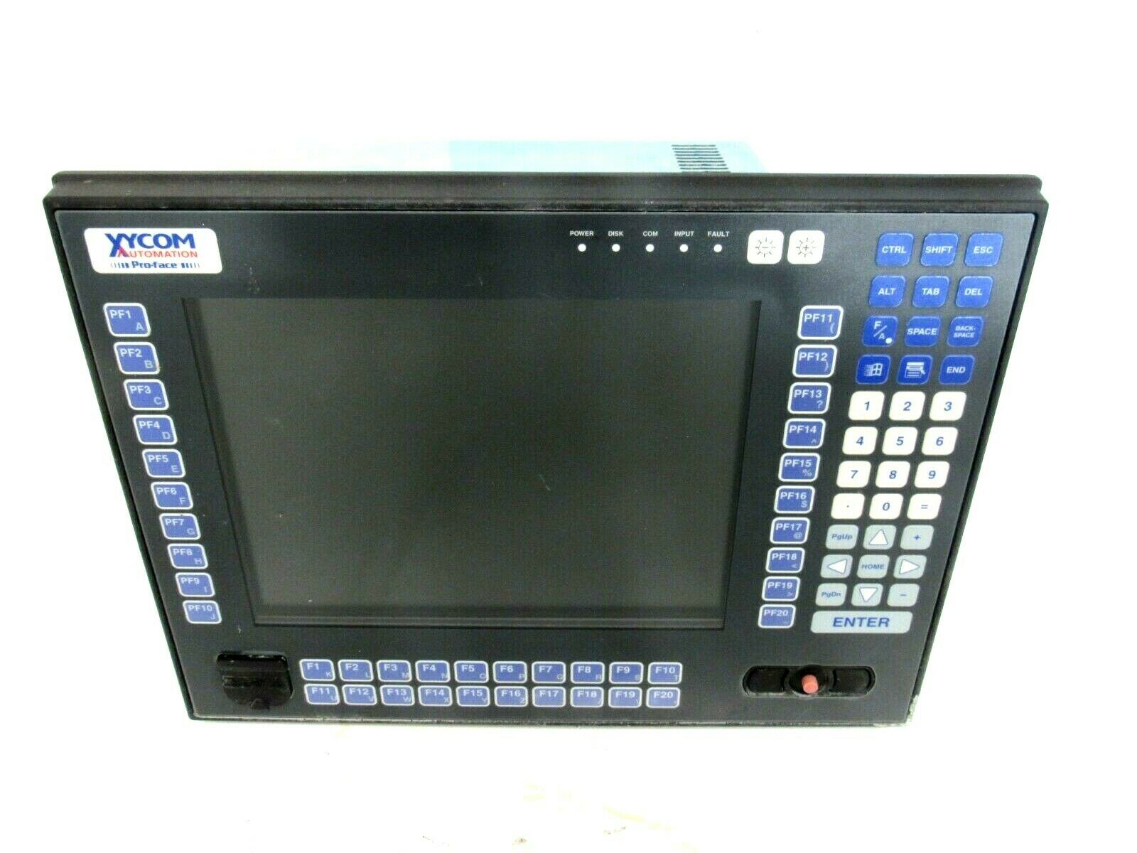
LCD monitor upgrade for 14 inch Xycom 9450 and Xycom 9403
Overview
The Xycom 9450 and 9403, as important equipment in the industrial control field, may experience issues such as blurry display and interface aging with their original 14 inch LCD displays after long-term use. The upgrade of the cable kit this time aims to meet the modern industrial demand for efficient visual monitoring and precise data exchange by improving display resolution, enhancing color expression, and optimizing interface connection stability, ensuring the continuous and stable operation of equipment in complex industrial environments.
Specification parameters
(1) Display parameters
Resolution: 1280 × 1024
Compared to the original monitor, the screen details are clearer, and the edges of text and images are smoother, making it suitable for displaying complex industrial drawings, fine data charts, and reducing the risk of information misreading
Brightness: 300cd/m ²
Even in industrial workshops with strong lighting, it can ensure clear and visible screen content, reduce the interference of reflection on the operator’s line of sight, and improve work efficiency
Contrast ratio: 1000:1
Make the bright parts of the screen brighter and the dark parts darker, and make the color differentiation of equipment operation status indicator lights, alarm prompts, etc. more prominent, making it easier to quickly identify abnormal situations
Display ratio: 4:3
Adapt to the original interface layout of Xycom 9450 and 9403, without the need for significant adjustments to device software display settings
Response time: 5ms
Effectively reducing dynamic image ghosting, the image is smooth and free of ghosting when the monitoring device is running quickly
(2) Cable kit parameters
HDMI cable
Length: Available in two specifications: 1.5 meters and 3 meters. 1.5 meters is suitable for compact installation scenarios of equipment, such as inside small control cabinets; 3 meters can meet the layout requirements of devices with long distances between them, such as connecting devices and displays installed in large workshops.
Transmission standard: Complies with HDMI 1.4 standard, supports 1080p high-definition video transmission, with a data transmission rate of 3.4Gbps, ensuring no delay or lag in image transmission, and realizing real-time high-definition monitoring of industrial production processes.
Material: Made of pure copper conductor and multi-layer shielding design, it can effectively resist electromagnetic interference in industrial environments, such as interference caused by motor operation and frequency converter operation, ensuring stable signal transmission and avoiding problems such as snowflakes and flickering on the screen.
VGA cable
Length: 2 meters standard length, suitable for most industrial equipment conventional installation distances, meeting the basic connection requirements between Xycom 9450 and 9403 and displays.
Interface type: Both ends are DB-15 male heads, using gold plating technology, with strong oxidation and corrosion resistance, low contact resistance, ensuring stable and reliable signal transmission, extending cable service life, and reducing the probability of display failures caused by poor interface contact.
Core functions
(1) High definition visualization upgrade
The upgraded monitor, with high resolution and excellent color performance, can clearly present industrial equipment operating parameters, real-time production process images, and complex engineering drawings. For example, in a machining workshop, parameters such as machine speed and feed rate can be clearly displayed; In chemical production monitoring, it can accurately present the pressure and temperature change curves of pipelines, helping operators to more accurately grasp the operating status of equipment, timely discover potential hazards, and provide reliable basis for production decisions.
(2) Flexible and stable connection
The cable kit offers a wide range of interface types (HDMI and VGA) and diverse length specifications, supporting flexible connection between the monitor and Xycom 9450, 9403, and other different types of industrial equipment. For old devices that are still using traditional VGA interfaces, stable connections can be achieved through VGA cables; For newly purchased high-performance industrial computers and other devices with HDMI interfaces, HDMI cables can achieve fast transmission of high-definition digital signals, improving device versatility and system integration. At the same time, the shielding design and high-quality interfaces of high-quality cables ensure stable and uninterrupted signal transmission in complex industrial electromagnetic environments.
(3) System compatibility optimization
This upgrade plan fully considers the system characteristics of Xycom 9450 and 9403, retaining the VGA interface to ensure compatibility with the original device system, making it convenient for users to gradually upgrade their devices without replacing all hardware, reducing costs and resource waste. At the same time, the newly added HDMI interface can adapt to the digital and intelligent upgrading needs of future devices, achieving a smooth transition between old and new devices.
Working principle
The upgraded monitor receives video and data signals from Xycom 9450 and 9403 devices through HDMI or VGA interfaces. The digital signal transmitted by HDMI cable can be directly received and processed by the digital processing chip of the display, quickly converted into high-definition images and displayed on the screen; The analog signal transmitted by VGA cable first goes through the A/D conversion module inside the display, which converts the analog signal into a digital signal. Then, the digital processing chip performs color correction, image scaling, and other processing to finally display a clear image. During cable transmission, its shielding layer effectively blocks external electromagnetic interference, while the anti-interference circuit inside the display further filters out clutter, ensuring signal integrity and accuracy, and achieving stable and high-definition display effects.
Upgrade Operation Guide
(1) Preparation work
Confirm that the Xycom 9450 and 9403 devices have been completely powered off, and turn off the power supply of related supporting equipment to avoid the risk of electric shock or equipment damage during operation.
Prepare the installation tools required for the upgrade, including a 14 inch LCD upgrade monitor, cable kit, screwdriver, anti-static wristband, etc. Wear anti-static wristbands to prevent damage to electronic components caused by human static electricity.
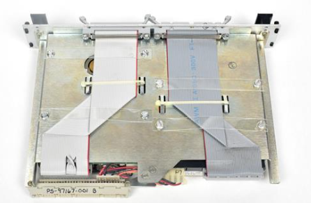
(2) Disassemble the original monitor
Use a screwdriver to unscrew the screws that secure the original monitor, carefully remove the monitor casing, and be careful to preserve the screws and casing components.
Carefully disconnect the cables connecting the original monitor to the Xycom 9450 and 9403 devices, remember the connection position and interface type of each cable, and take photos or record annotations for future reference when installing a new monitor.
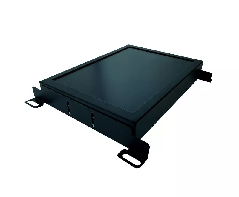
(3) Install a new monitor
Place the new monitor in its original installation position and secure the monitor housing with screws to ensure a secure installation. Tighten the screws appropriately to avoid damaging the monitor housing due to excessive tightness or loosening during device vibration.
Choose the appropriate cable (HDMI or VGA) based on the interface type of the Xycom 9450 and 9403 devices. If the device has an HDMI interface, prioritize using an HDMI cable. Connect one end of the cable to the device’s HDMI interface and the other end to the monitor’s HDMI interface; If the device only has a VGA interface, use a VGA cable for connection to ensure that the interface is tightly connected without looseness or skewness.
(4) Testing and Debugging
Connect the Xycom 9450, 9403 devices and monitor power, turn on the devices and monitor in sequence, and check if the monitor is displaying the image normally.
If the display is abnormal, first check whether the cable connection is correct and the interface is secure, and try unplugging the cable again; If the problem still persists, you can try replacing the cable for testing or checking if the device display settings are correct.
Enter the monitor settings menu and adjust parameters such as resolution, brightness, contrast, color mode, etc. according to actual needs to achieve the best display effect. At the same time, test whether the various functions of the monitor, such as menu operation and button response, are normal.
Precautions
(1) Installation and use
During the installation process, it is strictly prohibited to pull or tug on the cable with force to avoid internal conductor breakage or interface damage, which may affect the signal transmission performance. If the cable length is not suitable, do not forcefully stretch or bend it. Choose a cable of appropriate length for installation.
Do not use the monitor in harsh environments such as high temperatures (over 60 ℃), humidity (relative humidity greater than 85%), and strong magnetic fields (such as near large motors or transformers). If it is unavoidable to use in special environments, corresponding protective measures should be taken, such as installing a cooling fan, protective casing, and using shielding devices for the monitor.
Regularly check the connection of cables, especially after the equipment has been running for a period of time, as cables may become loose or fall off due to vibration or other reasons. Conduct a comprehensive inspection at least once a month to ensure a stable and reliable connection between the device and the monitor.
(2) Maintenance and upkeep
When cleaning the monitor screen, a dedicated screen cleaning cloth and cleaner should be used. First, gently wipe the surface of the screen to remove dust and stains. Avoid using rough fabrics or cleaning agents containing corrosive ingredients to prevent scratching the screen or damaging the screen coating. The cleaning frequency depends on the usage environment and frequency, generally cleaning once every 1-2 weeks.
Regularly dust the monitor by using dry compressed air or a soft bristled brush to clean the dust from the cooling holes, interfaces, and other parts of the monitor. Deep dust removal should be carried out every 3-6 months to maintain good heat dissipation and electrical connection performance of the equipment, prevent overheating and poor interface contact caused by dust accumulation, and extend the service life of the monitor.