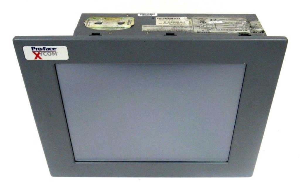
Xycom Automation industrial computers (IPCs) are designed to provide processing power and versatility.
The 4115T IPC offers a powerful pro cessor with a wide range of features and an expansion slot.
The 4115T also meets the rigorous requirements of the plant floor with a high resolution LCD flat panel display in a rugged housing ideal for today’s manufacturing environment.
Higher Performance
The 2.0 GHz Intel Pentium 4 CPU with 512 KB cache and 533 MHz system bus drives the fastest and most demanding applications.
Pre-loaded Operating Systems All 4115T systems come standard with either Windows 2000 or Windows XP pre-loaded.
The unit is also available with no operating system loaded.
Sharp, Easy-to-Read Displays A bright 15″ TFT screen can display complex operations with clarity.
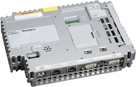
Full Complement of I/O Ports
The 4115T comes standard with an extensive array of I/O ports (see right), including two high-speed RS-232 ports, one configurable RS-232/422/485 port, one parallel port, two USB ports, PS/2 mouse & keyboard ports, one 10/100 Mbps Ethernet port, one VGA port, and audio I/O (input, output, and mic).
The VGA port can be used to connect a VGA monitor.
The built-in display and an external monitor can be used simulta neously (both showing the same image).
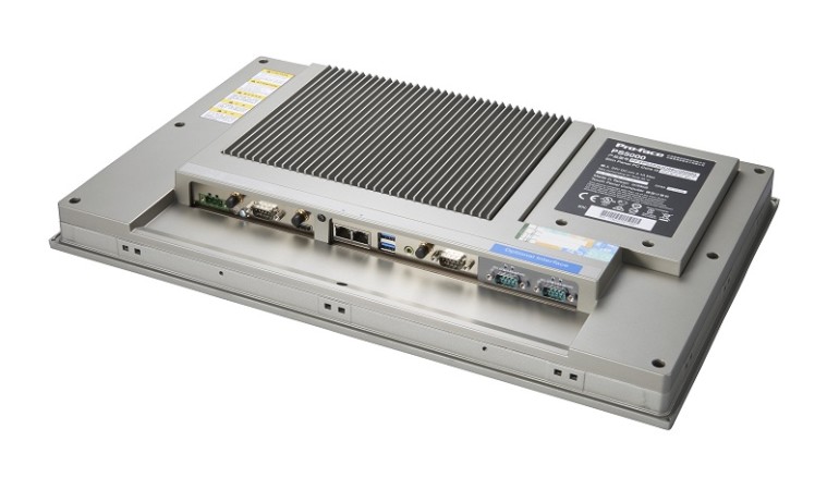
Temperature Specification
The 4115T has a faster, more powerful CPU which generates more heat than units with lesser performing
CPUs. Using Xycom’s expertise and experience, we have added a secondary system fan, more LCD venting, and a direct CPU vent channel to dissipate the extra heat.
When installing a higher performing CPU equipped unit into an enclosure, extra care should be exercised to ensure that the ambient air around the unit (inside your enclosure, not outside the enclosure) does not exceed 50° C. Exceeding 50° C may cause premature degeneration of the unit.
Consult your enclosure manufacturer for proper sizing and/or cooling options.
The product specifications and ratings section of this datasheet contains information your enclosure manufacturer will require.
PRODUCT CONFIGURATION
Model:4115T
Display:15″ LCD color display, 1024 x 768 (XGA)
Operator Input:Analog resistive touchscreen
Processor:Intel® Pentium® 4, 2.0 GHz
Preloaded OS 1:None, Windows® 2000, or Windows® XP
Expansion:One half-length PCI
Product Overview
Xycom Automation Pro – face Model 4115T is a high-performance computer designed specifically for the industrial automation field. It is equipped with a Pentium 4 2GHz processor and 640KB RAM, which can stably and efficiently run various industrial control programs and data processing tasks in industrial production processes. As a product under the PRO-FACE brand, it inherits the brand’s technological advantages and quality assurance in the field of industrial computers, aiming to provide reliable automation solutions for industrial users.
Specification parameters
Processor: Equipped with a Pentium 4 2GHz processor, it has strong computing power and can quickly process various instructions and data in industrial control processes, providing guarantees for the real-time performance of industrial automation systems. When faced with tasks such as real-time control instruction parsing and complex process parameter calculation of production line equipment, it can efficiently complete processing work.
Memory: Equipped with 640KB RAM, although the capacity may seem small in the current situation where computer memory is generally large, in industrial application scenarios, combined with optimized design of its operating system and control program, it can meet basic program running and data caching requirements. It can ensure the stable operation of industrial control software and ensure the smoothness of data processing and transmission.
Storage: Although specific storage information is not mentioned, as industrial computers, they are usually equipped with hard drives or other storage devices to store programs, configuration files, and historical data in the industrial production process, in order to meet the needs of data storage and management in industrial production.
Interfaces: Usually equipped with rich interfaces, such as Ethernet interfaces, serial ports (RS-232, RS-485, etc.), USB interfaces, etc. Ethernet interface can achieve connection with industrial networks, facilitating remote transmission of data and remote monitoring of devices; Serial ports are suitable for connecting various industrial sensors, instruments, and other devices to achieve data collection; The USB interface is convenient for external storage devices, printers, etc., meeting the diverse device connection needs of industrial sites.
Display: It has good display output capability and can support industrial grade displays, clearly displaying various monitoring screens, data charts and other information in the industrial production process, making it convenient for operators to intuitively understand the production status.
Core functions
Industrial automation control: As the core equipment of industrial automation systems, it can connect various devices on the production line, such as robots, CNC machines, conveyors, etc. By running pre written control programs, precise control of equipment is achieved, coordinating the workflow between various devices to ensure efficient and stable operation of the production line. For example, in the automotive manufacturing production line, the movements of robots can be precisely controlled to complete operations such as welding and assembly of automotive components.
Data collection and processing: Utilizing rich interfaces to collect real-time operational data of various equipment in industrial sites, such as temperature, pressure, speed, etc. Perform preliminary processing and analysis on the collected data, extract key information, and store or transmit it to other systems for further processing. Provide data support for the optimization, fault diagnosis, and quality control of industrial production processes.
Communication and Networking: Supports multiple industrial communication protocols such as Modbus, Profibus, etc., enabling seamless communication with devices from different manufacturers and achieving interconnectivity in industrial networks. Access the enterprise internal network or industrial Internet through the Ethernet interface to realize data sharing and remote monitoring. Managers can understand the situation of the production site at any time and anywhere, and conduct remote operation and management.
The PRO face Xycom 1341 egemin PM – 070016 computer, with the part number P/N 701301 – 01, is a specialized industrial – grade computing device. It belongs to the Xycom series by PRO – FACE, a brand renowned for its contributions to industrial automation. This model is designed to meet the specific demands of industrial environments, offering reliable performance and compatibility with various industrial systems.
Key Features
Fanless Design: As a fanless embedded controller, it is highly suitable for dusty or harsh industrial settings. The absence of fans reduces the risk of dust ingress, which could otherwise lead to component overheating and system failures. This design also minimizes noise, making it ideal for environments where quiet operation is preferred.
Configuration Options: It comes with options such as 1300 – 1GB – 4GB of memory, allowing users to choose the configuration that best suits their application requirements. Additionally, it can be equipped with an XP operating system along with a 1G bit PCI e – net card, enhancing its networking capabilities for seamless integration into industrial networks.
Reliable Performance: Having been sourced from factory surplus used stock in some cases, this computer has been fully tested to ensure it is in great working condition. Sellers often guarantee its functionality, providing a 100% assurance that it will operate as expected. In fact, some offer a 30 – day money – back warranty in case the product does not perform properly, instilling confidence in buyers.
Physical Specifications
Size and Weight: With estimated shipping dimensions of 9.5″ x 9.5″ x 4.0″ (24.1 cm x 24.1 cm x 10.2 cm) and a weight of 11 lbs 8.0 oz (5.2 kg), it has a compact form factor that can be easily installed in various industrial setups. However, its weight is substantial enough to suggest a sturdy build, which is typical for industrial – grade equipment designed to withstand vibrations and shocks.
Origin: This computer is manufactured in the United States, adhering to high – quality manufacturing standards. The country of origin often implies a certain level of quality control and reliability, which is crucial for industrial applications where downtime can be costly.
Applications
Industrial Automation: It can be used in industrial automation systems to control and monitor various processes. Its networking capabilities enable it to communicate with other devices in the automation setup, such as sensors, actuators, and other controllers. For example, in a manufacturing plant, it could be used to manage the operation of conveyor belts, robotic arms, or other automated machinery.
Data Acquisition and Monitoring: With its ability to handle different memory configurations and network connectivity, it is well – suited for data acquisition and monitoring tasks. It can collect data from multiple sensors in an industrial environment, such as temperature, pressure, or flow sensors, and transmit this data to a central control system for analysis. This makes it valuable in industries like oil and gas, where continuous monitoring of process variables is essential for safe and efficient operation.
Xycom 2050T interface workstation is a powerful interface workstation designed to provide efficient and stable connectivity and data exchange capabilities for industrial automation and control systems. It plays a key role in industrial production environments, enabling data transmission and communication between different devices and systems, ensuring the collaborative operation of the entire industrial system. The model suffix and accompanying parameters “1.12/. 70AMP 110/240Vac 12” further clarify some characteristics of the device, such as possible version information, electrical specifications, etc., which enable it to adapt to diverse industrial scene requirements.
Brand background
Continuing the profound foundation of PRO-FACE in the field of industrial automation, the Xycom 2050T interface workstation inherits the brand’s consistent pursuit of quality and innovation. With years of technological accumulation in industrial computers and human-computer interfaces, PRO-FACE has endowed Xycom 2050T with reliable performance and powerful functions, making it highly competitive in the industrial market and a trusted choice for many industrial enterprises.
Specification parameters
Electrical parameters: According to “70AMP 110/240Vac”, the current carrying capacity of this workstation can reach 70 amperes, with an input voltage range of 110-240Vac AC. This wide voltage input design enables it to adapt to the application needs of different regions and power environments, and has good power compatibility.
Interface configuration: As an interface workstation, its core lies in a rich and diverse range of interface types. Although the specific types of interfaces are not yet clear, they usually include Ethernet interfaces, serial ports (such as RS-232, RS-422, RS-485, etc.), USB interfaces, etc., to meet the connection requirements with various industrial equipment such as sensors, controllers, actuators, etc., and achieve efficient data transmission and communication.
Performance parameters: Equipped with a powerful processor and sufficient memory, it can quickly process large amounts of industrial data and complex communication protocols, ensuring stable and efficient operation even in multi device connections and large data transmission. At the same time, high-capacity storage devices can be used to store system programs, device configuration information, and important industrial data records.
Core functions
Data Communication and Protocol Conversion: Supports multiple industrial communication protocols such as Modbus, Profibus, Ethernet/IP, etc., enabling data communication and protocol conversion between devices with different protocols. In complex industrial systems, devices from different manufacturers may use different communication protocols. The Xycom 2050T interface workstation can act as a “translator” to enable these devices to “talk” to each other, achieving smooth data exchange and sharing.
Equipment connection and centralized management: Through rich interfaces, a large number of industrial equipment can be connected, and various devices scattered in the industrial field can be centrally connected to workstations. Users can centrally manage, configure, and monitor connected devices through workstations, obtain real-time operational status information of devices, and improve the management efficiency and operational convenience of industrial systems.
Data processing and analysis: Possess certain data processing capabilities, able to perform real-time analysis, processing, and storage of collected industrial data. For example, conducting statistical analysis on equipment operation data, predicting equipment failures, conducting maintenance in advance, reducing equipment downtime, and ensuring the continuity and stability of industrial production.
Working principle
The Xycom 2050T interface workstation operates based on computer architecture and communication technology principles. After connecting to industrial equipment, receive data signals sent by the equipment through the corresponding interface, and parse the data according to the preset communication protocol. The parsed data is transmitted to the processor of the workstation for processing, and the processor performs analysis, calculation, and other operations on the data according to program logic. After processing, the data can be stored according to requirements, or converted according to other protocols and sent to other devices or systems through corresponding interfaces. At the same time, the workstation provides users with an operation interface for device management and data monitoring through human-computer interaction interfaces (such as display screens, operation panels, etc.). Users can send instructions through the interface to control the operation of the workstation and equipment.
Key advantages
High compatibility and flexibility: With powerful protocol support and rich interface configurations, it can be compatible with the vast majority of industrial equipment on the market, whether it is upgrading and renovating old equipment or integrating new equipment, it can easily cope. Meanwhile, users can flexibly configure interfaces and communication protocols according to their actual needs to meet diverse industrial application scenarios.
Reliable stability: Adopting industrial grade hardware design and manufacturing processes, it has good anti vibration, anti impact, dustproof and waterproof capabilities, and can operate stably in harsh industrial environments. At the same time, through rigorous testing and verification, it ensures reliable performance even under long-term continuous operation, reducing the risk of equipment failure.
Efficient data processing capability: High performance hardware configuration and optimized data processing algorithms enable it to quickly process large amounts of industrial data, ensuring real-time and accurate data communication. In industrial automation production, timely and accurate data processing is crucial for controlling and optimizing the production process, and the Xycom 2050T interface workstation can meet this requirement.
Precautions
Installation and electrical connection: During installation, it is necessary to strictly follow the requirements of the product manual to ensure a stable installation position and good ventilation. When making electrical connections, it is necessary to confirm that the input voltage matches the equipment specifications, use appropriate power cords, and ensure good grounding to prevent electrical faults and safety accidents.
Interface usage and device connection: Before connecting the device, it is necessary to clarify the interface type, communication protocol, and electrical parameters of the device to ensure compatibility with the workstation interface. When connecting, avoid excessive pulling or bending of the interface cable to prevent damage to the interface. At the same time, pay attention to the plugging and unplugging sequence of interfaces, and avoid randomly plugging and unplugging interfaces during device operation to avoid data loss or device damage.
Software configuration and maintenance: When configuring software, it is necessary to use the official configuration tools and software provided, and follow the correct operating procedures for setting up. Regularly update the system software and drivers of the workstation to fix vulnerabilities and improve performance. At the same time, do a good job in data backup to prevent production interruptions caused by software failures or data loss.
Similar model supplement
Xycom 2060T: As a product in the same series, Xycom 2060T has similarities in functionality and architecture with 2050T, but may have upgrades in performance and interface configuration. For example, it may be equipped with more powerful processors that provide higher computing power to meet more complex data processing requirements. In terms of interfaces, new types of interfaces may have been added or the transmission rate of interfaces may have been improved, further enhancing the device’s connectivity and data transmission efficiency.
Xycom 1950T: Compared to 2050T, Xycom 1950T may be slightly inferior in performance and functionality, but still has advantages in some specific industrial scenarios. For example, in small industrial systems that are cost sensitive and have relatively low data processing requirements, the 1950T, with its relatively economical price and stable basic performance, can meet basic equipment connection and data communication needs.
XYCOM 1546 PROFACE Industrial Computer with RS View 32 Batch Q302 is a high-performance computer device designed specifically for harsh industrial environments. It combines powerful computing power, rich interface configuration, and excellent stability, aiming to meet the needs of various complex industrial application scenarios such as industrial automation, process control, data acquisition and monitoring. This computer has a compact design, making it easy to install and deploy in environments with limited space such as factory workshops and control cabinets. At the same time, its sturdy and durable casing can effectively resist the effects of harsh factors such as vibration, impact, dust, and moisture, ensuring long-term reliable operation in various industrial sites.
Specification parameters
Processor: Supports Intel ® socket 478 Celeron ® M or Pentium ® M option, up to 2.0GHz, 400MHz or 533MHz front-end bus (depending on processor type), can efficiently handle various complex industrial control algorithms and data computation tasks.
Memory: Equipped with two 240 pin DDR2 DIMM slots, supporting multiple capacity options of 256MB, 512MB, 1GB, and 2GB. The system DRAM can reach 4M and can be expanded up to 32M, ensuring smooth program operation and efficient performance even during multitasking.
Storage: Provides CompactFlash ™ Option, supports up to 4GB, can be used to store important industrial data, program files, and system configuration information.
Interface: It has four serial COM ports, with three external ports configured as RS-232 and one configurable as RS-232, RS-422, or RS-485, making it convenient for serial communication with various industrial equipment; Simultaneously equipped with other common interfaces such as Ethernet interface, USB interface, etc., to meet the connection requirements of different devices.
Display: AGP video controller with 4M system memory, capable of providing clear and stable image display effects, meeting the display needs of industrial monitoring screens.
Power supply: The input voltage range is 100-240VAC, frequency is 50-60Hz, current is 1A, suitable for power supply environments in different regions, and has good power supply stability and anti-interference ability.
Environmental parameters: The maximum ambient temperature can reach 50 ° C, temperature code T6, in compliance with Class I, Division 2, Groups A, B, C, and D standards, and can operate stably in harsh environments such as high temperatures and potentially explosive gases.
Excessive Heat
The units withstand temperatures from 0º to 50ºC, and are fan-cooled.
To keep the temperature in range, the cooling air at the base of the system must not exceed 50°C.
Allocate proper spacing between internal components installed in the enclosure.
Electrical Noise
Electrical noise is seldom responsible for damaging components, unless extremely high energy or high voltage levels are present.
However, noise can cause temporary malfunctions, which can result in hazardous machine operation in certain applications.
Noise may be present only at certain times, may appear at widespread intervals, or in some cases may exist continuously.
Noise commonly enters through input, output, and power supply lines and may also be coupled through the capacitance between these lines and noise signal
carrier lines.
This usually results from the presence of high voltage or long, close spaced conductors.
When control lines are closely spaced with lines carrying large currents, the coupling of magnetic fields can also occur.
Use shielded cables to help minimize noise.
Potential noise generators include switching components, relays, solenoids, motors, and motor starters.
Refer to the relevant Federal, State/Provincial, and local electric codes, which provide data such as the size and types of conductors, color codes and connections necessary for safe grounding of electrical components.
It is recommended that the high voltage and low voltage cabling be separated and dressed apart. In particular,the AC cables and switch wiring should not be in the same conduit with all communication cables.
Line Voltage Variation
The unit’s power supply is built to operate with an input voltage range of 100 240VAC, while still allowing the system to function within its operating margin.
As long as the incoming voltage is adequate, the power supply provides all the logic voltages necessary to support the processor, memory, and I/O.
In cases in which the installation is subject to unusual AC line variations, use a constant voltage transformer to prevent the system from shutting down too often.
However, a first step toward the solution of the line variations is to correct any possible feed problem in the distribution system. If this correction does not solve
the problem, use a constant voltage transformer.
The constant voltage transformer stabilizes the input voltage to the 1546 and 1547 units by compensating for voltage changes at the primary in order to maintain a steady voltage at the secondary.
When using a constant voltage transformer, check that the power rating is sufficient to supply the unit.
AC Power Cable
A power cable must be created to supply power to the unit.
The following materials are needed:
A three-position power connector (supplied)
A braid/foil shielded power cable, terminated at power source end, with three 18 (1.0 mm), 16 (1.3 mm), or 14 (1.6 mm) AWG solid or stranded copper
wires, rated 80ºC or better
Perform the following steps to construct and attach the cable:
Cut wire cable to the desired length.
Strip 0.25-inch (6 mm) of insulation from the end of the conductor wire. No bare wire should be exposed when the cable is connected to the workstation.
Tin the wire ends with solder if using stranded wire.
This will keep the wire from fraying.
Insert the three wire ends of the power cable into the hole of the connector plug.
Bend the Protective Earth ground (PE) wire, the neutral (N) wire, and the line(L) wire around the corresponding screw. Be sure that no bare wires are exposed.
Tighten the three screws above the wires to hold them firmly in place..
Use the screw provided to secure and strain-relief the power cable inside the connector.
Plug the power cable into the power supply located on the side of the unit.
Install the plug retainer bracket over the plug (mandatory for hazardous location installations).
Once the power cable and other optional interface cables are installed, installation is complete.
DRAM and Additional DRAM Dual Inline Memory Modules DIMMs)
You can order the 1546/1547 system CPU factory-configured for many configurations of DRAM.
The system has two 240-pin DDR2 DIMMs that support 512, 1GB and 2GB options.
The maximum amount supported is 2GB.
You can reconfigure the DDR2 capacity by changing the DDR2 DIMMs on your board.
PC/AT® and PCI Boards
Check the memory and I/O configuration of the board you want to install so that it does not conflict with the CPU and I/O memory maps in your AIM4
documentation.
Remove the lid.
Remove the ORB screw from the desired slot.
Slide the PC/AT expansion board into the corresponding rail.
Push the board into the backplane connectors.
Secure the board by installing the screw through the hole in the board’s metal
ORB and into the top of the track.
Replace the lid.
Hazardous Locations Installation
Xycom Automation designed the 1546 and 1547 Node Box Industrial PCs to meet the requirements of Class I, Division 2 Hazardous Locations applications. Division 2 locations are those locations that are normally non-hazardous, but could become hazardous due to accidents that may expose the area to flammable vapors, gases or combustible dusts.
These systems have been designed as non-incendiary devices.
They are not intrinsically safe and should never be operated within a Division 1 (normally hazardous) location when installed as described here.
Nor should any peripheral interface device attached to these systems be located within Division 1 locations unless approved and/or certified diode barriers are placed in series with each individual signal and DC power line.
Any such installations are beyond the bounds of Xycom design intent.
Xycom Automation accepts no responsibility for installations of this equipment or any devices attached to this equipment in Division 1 locations.
The 1546 and 1547 Node Box Industrial PCs offer a powerful, compact package for the factory floor and other harsh environments.
These node box industrial PCs feature an open architecture to meet a wide variety of applications that require both a powerful PC and a durable industrial enclosure.
The systems integrate a computer card cage, mass storage, and power supply in a truly industrial form.
The processor board combines all the functions of a complete PC/AT® compatible computer on a single industrially hardened circuit board.
Standard Features
The 1546 and 1547 units come standard with the following features:
AIM4 board
Wall or shelf mountable
Flash BIOS
SATA HD controller for up to 2 drives
Removable 40 GB SATA hard drive(s), rear access
AGP Video Controller, 4M of system DRAM, up to 32M
PCI local bus IDE controller (for CD/DVD and CF options)
Two 240 pin DDR2 DIMM sockets that support 256MB, 512MB, 1GB and 2GB options
Intel® Socket 478 Celeron® M or Pentium® M options up to 2.0GHz 400MHz or 533MHz front side bus depending on the processor type 1546 – Four AT bus expansion slots
One PCI (8.0” max)
One PCI (9.0” max)
One ISA (9.0” max)
One PCI or ISA slot (9.0” max)
1547 – Four AT bus expansion slots
One ½ length PCI
One full length PCI
One full length ISA
One full length PCI or ISA slot
IBM® PS/2® keyboard port and mouse port
Four serial COM ports, with three external ports configured as RS-232 and one
configurable as either RS-232 or RS-422 or RS-485. The fourth port is an
internal header only and defaulted as disabled.
Parallel port
VGA port
Four USB 2.0 ports
Legacy USB keyboard and mouse support
Legacy USB floppy, USB CDROM, and USB mass storage support
Two onboard Ethernet ports, one is a 10/100 BASE T and the other is 10/100/1000 BASE T
Microsoft Windows XP® operating system
Internal rear access Compact Flash (CF) interface 120/240 VAC 50/60Hz Auto switching power supply
UL Listed for use in Class I and Class II, Division 2 hazardous locations, Groups
A, B, C, D, F, and G
Optional Features
Following are optional available features of the 1546 and 1547:
Higher capacity SATA hard drives and solid state drives
Various CD/DVD drive options
Internal rear access floppy
Various processor speeds
Preinstalled Windows® 2000, or Windows XP® Professional
External 9000-USBF, USB floppy (requires Windows 2000, or XP)
CompactFlash™ options up to 4GB
2.5” Dual hard drives
2.5” RAID array support
24VDC power supply (on 1547 units only)
The figures and tables on the next several pages illustrate the internal and external components on the front and back panels of the unit to help you locate the features of the 1546 and 1547 Node Boxes.
Unpacking the System
When you remove the system from its shipping container, verify that you have the parts listed below.
Save the box and inner wrapping in the event you need to reship the unit.
1546 or 1547 unit
Documentation kit, which includes:
Power connector
Cable clamp and screw (for strain relief of power cord)
Documentation and Support Library CD-ROM
Operating System Recovery Media or retail operating system (CD-ROM)
Mounting hardware
The rugged design of the 1546 and 1547 Node Boxes allows it to be installed in most industrial environments.
The system is generally placed in a NEMA 4/4X/12 enclosure to protect against contaminants such as dust, and moisture.
Metal enclosures also help minimize the effects of electromagnetic radiation that nearby equipment can generate.
For Underwriters Laboratories (UL) compliance, the unit must be installed within a suitable fire enclosure.
Read the following sections carefully to be sure that you are complying with all the safety requirements.
Select a NEMA rated enclosure and place the unit to allow easy access to the system ports (see other sections in this chapter and Appendix A).
To assure a NEMA 4 seal choose an approved enclosure that has a 14-gauge (0.075 in/1.9 mm thick steel or 0.125 in/3.2 mm thick aluminum) front face.
Be sure to account for the unit’s depth when choosing the depth of the enclosure.
Create a mounting location in the enclosure (see System Mounting Dimensions).
Be sure to place the unit at a comfortable working level
Make sure the area around the mounting location is clean and free from metal burrs
Mount the unit position and properly secure the unit into the panel.
Tighten the fourteen #10 screws to 20 inch-pounds (2.597 Newton-meters /23Kgf cm).
Construct a power cable following the instructions in AC Power Cable in this chapter..
Attach one end of the power cord to the power receptacle on the unit and the other end to a properly grounded 115/230 VAC, 50-60 Hz outlet.
A ground path from the unit chassis to the enclosure chassis can be established using the 6-32 threaded ground point hole provided on the bottom panel of the unit
Turn on power to the system. The system will boot up the installed operating system.
Install the application software via a floppy drive, CD-ROM, or the network.
Additional aspects to take into account when mounting your 1546 and 1547 Node
Boxes:
Consider locations of accessories such as AC power outlets and lighting (interior lighting and windows) for installation and maintenance convenience
Prevent condensation by installing a thermostat-controlled heater or air conditioner
To allow for maximum cooling, avoid obstructing the airflow
Place any fans or blowers close to the heat generating devices.
If using a fan, make sure that outside air is not brought into the enclosure unless a fabric or other reliable filter is used.
This filtration prevents conductive particles and other harmful contaminants from entering the enclosure.
Do not select a location near equipment that generates excessive electromagnetic interference (EMI) or radio frequency interface (RFI).
Examples of these types of equipment are: high power welding machines; induction heating equipment;and large motor starters.
Place incoming power line devices (such as isolation or constant voltage transformers, local power disconnects, and surge suppressers) away from the
system.
The proper location of incoming line devices keeps power wire runs as short as possible and minimizes electrical noise transmitted to the unit.
Make sure the location does not exceed the unit’s shock, vibration, and temperature specifications
Install the unit in the rack or panel in such a way as to ensure that it does not cause a hazard from uneven mechanical loading
Incorporate a readily-accessible disconnect device in the fixed wiring on permanently connected equipment
Avoid circuit overloading of the supply circuit
Power Management
The following paragraphs explain the system power, the power supply, and the effects of excessive heat, electrical noise, and line voltage variation of the 1546
and 1547 Node Boxes.
System Power
Using isolation transformers on the incoming AC power line to the system is always a good practice. An isolation transformer is especially desirable in cases in
which heavy equipment is likely to introduce noise onto the AC line.
The isolation transformer can also serve as a step-down transformer to reduce the incoming line voltage to a desired level. The transformer should have a sufficient power rating (units of volt-amperes) to supply the load adequately.
Proper grounding is essential to all safe electrical installations.
Refer to the relevant Federal, State/Provincial, and local electric codes, which provide data
such as the size and types of conductors, color codes and connections necessary for safe grounding of electrical components.
The code specifies that a grounding path must be permanent (no solder), continuous, and able to safely conduct the ground-fault current in the system with minimal impedance (minimum wire required is #18 AWG, 1 mm).
Observe the following practices:
Separate ground wires (P.E. or Protective Earth) from power wires at the point of entry to the enclosure.
To minimize the ground wire length within the enclosure,locate the ground reference point near the point of entry for the plant power supply.
All electrical racks or chassis and machine elements should be Earth Grounded in installations where high levels of electrical noise can be expected.
The rack/chassis should be grounded with a ground rod or attached to nearby Earth structure such as a steel support beam.
Each different apparatus should be connected to a single Earth Ground point in a “star” configuration with low impedance cable.
Scrape away paint and other nonconductive material from the area where a chassis makes contact with the enclosure.
In addition to the ground connection made through the mounting bolt or stud, use a one-inch metal braid or size #8 AWG wire to connect between each chassis and the enclosure at the mounting bolt or stud.
Xycom Automation industrial monitors meet the rigorous requirements of the plant floor with high-resolution flat panel displays in a rugged housing with an optional resistive membrane touchscreen.
The XT1502 flat panel monitor delivers crisp, bright text and graphics with a low current draw, and it fits into panels that CRTs cannot.
The XT1502 is self-contained, requiring only to be panel mounted in an appropriate enclosure and connected to 120/240 VAC and VGA source
Standard XT1502 Features
• 15.0″ bright (200 Nit), easy-to-read, high contrast (150:1), color (6 bit/262,144 colors) TFT flat panel display with SVGA (1024×768) resolution
• Large viewing area and viewing angles (120° horizontal, 100° vertical)
• Operator input through an optional integrated high-performance (35 million touch) touchscreen
• Front panel controls with onscreen menus (lock switch on rear of units)
• Long-lasting (50,000 hour) backlight
• Hinged design for easy backlight field replacement
• Simple mounting
• Shallow mounting depth
• Up to 50 foot cables
• Optional 19″ EIA rackmount adapter plate
• NEMA 4/12 front panel, when properly mounted
• UL and cUL recognized, CE marked
• Units ship with all necessary cables and software
Parts List
When you remove the XT1502 from its shipping carton, verify that you have the parts listed below.
Save the box and inner wrapping in case you need to reship the unit.
Standard XT1502 Parts List
• XT1502 unit.
• Ten-foot VGA cable.
• Ten-foot serial cable (touchscreen units only).
• Documentation and Support Library CD-ROM. In addition to containing this manual, this CD contains all drivers required by this unit (touchscreen drivers in the case of XT1502T units)
Manual Overview
The manual is divided in the following chapters:
• Chapter 1 – Product Overview
• Chapter 2 – Installation
• Chapter 3 – Monitor Settings
• Chapter 4 – Hardware
Text Conventions Used in this Manual
Throughout this manual, certain terms are formatted in ways that indicate what type of object is being described.
Some information is also segregated to draw attention quickly.
Titles, labels, and messages are indicated by italic text.
Computer filenames and text to be entered by the user will appear in a monospace font.
Operator interfaces (such as the Start menu button) and keyboard keys (such as Enter) appear in a narrow bold typeface.
Other text (such as the word Note) is bold to emphasize it and draw your attention to it.
Some text is segregated into Note, Caution, or Warning boxes.
Notes contain extra information that may make the nearby text, especially the text just before the note, more understandable.
Cautions contain information necessary to prevent damage to the hardware.
Warnings contain information necessary to safeguard the operator.
System Power
It is a good practice to use isolation transformers on the incoming AC power line to the system.
An isolation transformer is especially desirable in cases in which heavy equipment is likely to introduce noise onto the AC line.
The isolation transformer can also serve as a step-down transformer to reduce the incoming line voltage to a desired level.
The transformer should have a sufficient power rating (units of volt-amperes) to supply the load adequately.
Proper grounding is essential to all safe electrical installations. Refer to the relevant federal, state/provincial, and local electric codes, which provide data such as the size and types of conductors, color codes and connections necessary for safe grounding of electrical components.
The code specifies that a grounding path must be permanent (no solder), continuous, and able to safely conduct the ground-fault current in the system with minimal impedance (minimum wire required is 18 AWG, 1 mm).
Observe the following practices:
• Separate the power and ground (P. E., or Protective Earth) cable from signal cables at the point of entry to the enclosure.
To minimize the ground wire length within the enclosure, locate the ground reference point near the point of entry for the plant power supply.
• All electrical racks or chassis and machine elements should be Earth Grounded in installations where high levels of electrical noise can be expected.
The rack/chassis should be grounded with a ground rod or attached to a nearby Earth structure such as a steel support beam.
Connect each different apparatus to a single Earth Ground point in a “star” configuration with low impedance cable.
Scrape away paint and other nonconductive material from the area where a chassis makes contact with the enclosure.
In addition to the ground connection made through the mounting bolt or stud, use a one-inch metal braid or size #8 AWG wire to connect between each
chassis and the enclosure at the mounting bolt or stud.
Excessive Heat
To keep the temperature in range, the cooling air at the base of the system must not exceed the maximum temperature specification (see pg. 1-4).
Allocate proper spacing between internal components installed in the enclosure.
When the air temperature is higher than the specified maximum in the enclosure, use a fan or air conditioner to lower the temperature.
Location and Enclosure
• Place the unit to allow easy access to the system ports.
• Account for the unit dimensions when selecting an installation location or enclosure
• You can maintain the NEMA 4 seal by mounting the unit in an approved enclosure that has a 14 gauge (0.075″/1.9 mm thick) steel or (0.125″/3.2 mm thick) aluminum front face.
• Place the unit at a comfortable working level.
• Mount the unit in an upright position, if possible.
• Consider locations of accessories such as AC power outlets and lighting (interior lighting and windows) for installation and maintenance convenience.
• Prevent condensation by installing a thermostat-controlled heater or air conditioner.
• Avoid obstructing the airflow to allow for maximum cooling.
• Place any fans or blowers close to the heat-generating devices.
If using a fan, make sure that outside air is not brought inside the enclosure unless a fabric or other reliable filter is used.
This filtration prevents conductive particles or other harmful contaminants from entering the enclosure.
• Do not select a location near equipment that generates excessive electromagnetic interference (EMI) or radio frequency interface (RFI) (equipment such as high-power welding machines, induction heating equipment, and large motor starters).
• Do not place incoming power line devices (such as isolation or constant voltage transformers, local power disconnects, and surge suppressers) near the system.
The proper location of incoming line devices keeps power wire runs as short as possible and minimizes electrical noise transmitted to the unit.
• Make sure the location does not exceed the unit’s shock, vibration, and temperature specifications
• Install the unit so it does not cause a hazard from uneven mechanical loading.
• Incorporate a readily accessible disconnect device in the fixed wiring on permanently connected equipment.
• Avoid overloading the supply circuit
Back Light Replacement Procedure
After 50,000 hours of use, the two lamps used for LCD back lighting may become dim or burn out. You may return the monitor to Xycom for lamp replacement or you can order new lamps and follow the procedure below to install them.
You can perform the lamp replacement procedure without removing the monitor from the NEMA enclosure where it is mounted, but you should do this only in a clean environment.
Otherwise, the procedure is better performed at a service bench.
1. TURN THE MONITOR POWER OFF AND DISCONNECT THE LINE CORD
2. Loosen the four thumbscrews that hold the back of the monitor on.
3. Separate the two halves of the monitor. If the unit is equipped with a touchscreen, you will have to disconnect its cable.
4. The lamps are mounted in small plastic carriers that slide in the right side of the LCD display at the top and bottom edges.
5. Note their orientation and then unplug the two sets of lamp wires (3″ pink and white silicone wires) from the nearby inverter.
6. Look in the hole where the lamp is presently installed and note the small black locking tab on the front side of each hole. With a small slotted screwdriver, depress the tab while carefully pulling on the wires and slide the lamps outward.
Discard the old lamps.4-1 VGA Input Connector Pin Out
7. Carefully slide the new lamps fully into place noting the top lamp has a small triangle molded in the end where the wires protrude. Similar triangles a stamped in the LCD sheet metal near the top hole.
8. Reconnect the lamp wires to the inverter. These are keyed connectors permitting insertion in only one orientation.
9. You may now want to clean the LCD and the inside of the monitor window or touchscreen with a slightly damp soft cloth.
10. Carefully reunite the two monitor halves remembering to reconnect the touchscreen cable if the unit is so equipped.
11. The lamp replacement procedure is now complete.
Xycom Pro Face 1546 Industrial Computer 2000-1000- DVDW – XP is a high-performance computer device designed specifically for harsh industrial environments. As an important product of the Xycom series under Pro face, it combines powerful computing power, rich storage options, and stable operational performance to meet the complex application needs of industrial automation, process control, factory monitoring, and other fields, providing reliable computing and data processing support for industrial production.
Specification parameters
(1) Electrical parameters
Voltage input: Supports a wide voltage range of 100-240VAC input, which enables it to flexibly adapt to power grid standards in different regions around the world. Whether in North America with a voltage of 110VAC or in most regions of Europe and Asia with a voltage of 220VAC, there is no need for additional voltage conversion equipment and it can be directly connected to the power grid, greatly reducing equipment deployment costs and complexity, and providing convenience for the implementation of industrial projects by multinational enterprises.
Frequency range: It can operate stably at a frequency of 50-60Hz, adapt to the frequency differences of power grids in different countries and regions, ensure stable power supply for equipment in various industrial environments, guarantee the normal operation of computer systems, and avoid performance fluctuations or failures caused by frequency mismatch.
Power related: Although the specific value of power has not been given, it is inferred from its design positioning and hardware configuration that the overall power of the machine can meet the stable operation requirements of internal high-performance processors, storage devices, and other components. At the same time, energy efficiency optimization is emphasized in power supply design. While ensuring performance, energy consumption is minimized as much as possible to reduce equipment operating costs, which is in line with modern industry’s pursuit of energy conservation and efficiency.
(2) Hardware configuration
Processor: Using Intel ® Socket 478 Celeron ® M or Pentium ® M processor option, up to 2.0GHz, 400MHz or 533MHz front-end bus (depending on processor type). For example, when using Pentium ® When the M 2.0GHz processor is paired with 2M cache and 533MHz system bus, it performs excellently and can quickly handle various complex computing tasks in industrial automation systems, such as real-time data acquisition and analysis, equipment operation status simulation, control algorithm execution, etc., providing powerful computing power for the efficient operation of industrial production processes. Its computing speed and processing capacity far exceed ordinary computers of the same level, effectively reducing system response delay and improving production efficiency.
Memory: Equipped with two 240 pin DDR2 DIMM slots, supporting 256MB, 512MB, 1GB, and 2GB memory options, users can flexibly expand memory capacity according to actual application needs. In data intensive industrial application scenarios, such as large-scale data storage and retrieval, complex production simulation, etc., the memory can be expanded to 2GB to ensure smooth operation of the system during multitasking, avoiding problems such as program lag and slow data processing caused by insufficient memory, and improving the overall performance and stability of industrial computers.
Storage:
Hard drive: comes standard with a removable 40GB SATA hard drive and rear access function, making it easy to maintain, replace, or backup data on the hard drive during device operation. At the same time, the hard drive capacity can be upgraded to 80GB or even higher according to actual needs to meet the storage needs of large amounts of industrial data. For example, in the field of industrial monitoring, long-term equipment operation data, video surveillance recordings, etc. require large capacity storage support. By upgrading the hard drive, data can be ensured not to be lost, providing sufficient data resources for subsequent data analysis and fault tracing.
Optical drive: equipped with a rear access read-write DVD ROM drive, which can be used for software installation, reading disc data, and data backup. In industrial production, some device drivers, industrial software installation packages, etc. are often provided in the form of CDs. Through this DVD-ROM drive, relevant programs can be easily and quickly installed into computer systems to ensure the normal operation and functional expansion of equipment. In addition, important data can also be stored for a long time by burning CDs to improve the security and stability of data storage.
Other storage options: Supports CompactFlash ™ Option, up to 4GB. CompactFlash ™ Cards have the advantages of small size, fast storage speed, and strong earthquake resistance. They can be used to store critical system files, configuration data, or temporary data cache. In industrial environments, their excellent earthquake resistance can effectively prevent data loss or damage caused by equipment vibration, providing additional protection and flexibility for data storage in industrial computers.
Higher Performance,
Lower Power
The 1546 utilizes an Intel mobile processor providing superior processing power while
utilizing half the wattage of a comparable Pentium 4 processor.
The optional Pentium M2.0 GHz processor (2 M CACHE & 533 MHz system bus) outperforms a desktop Pentium 4 2.4 GHz (512 K CACHE & 533 MHz bus) while utilizing less than half the wattage.
The increased processing power with less heat generation makes the 1546 ideal for most factory automation applications requiring a NEMA enclosure.
Less wattage input into the system results in less tempera ture rise in the enclosure.
With less temperature rise the maximum ambient operating temperature is more easily maintained, possibly without the need for expensive enclosure cooling devices.
Superior Video
Performance
The on-board 4X AGP graphics controller defaults to 4 MB system RAM to allow resolutions up to 1280 x 1024.
In addition the 1546 automatically shares up to 32 MB system RAM to allow full 32-bit color depth
and fast 3D rendering.
Fits Your Needs
The 1546 can be configured many different ways.
With four available expansion slots many cost effective, industry standard options are easily integrated.
The optional dual hard drive, externally accessibl
CompactFlash, or RAID-enabled configura tion provides the storage solution you require.
Additionally the CD-ROM can be upgraded to CD-R/W or DVD-R/W providing even more storage and backup options.
Meets High Standards
To survive on the plant floor the 1546 meets FCC, UL, cUL, and European CE mark requirements for industrial automation equipment.
Xycom Automation Industrial PCs lead the industry in reliability, service, and support with an optional five year warranty available
EASILY REPLACEABLE HARD DRIVE
The 1546 unit has incorporated a simple to access hard drive mount. Simply loosen 2 captive screws and extract the hard drive.
No cables to install or connect.
Simply plug in the new drive. Optional dual hard drives or RAID-enabled configurations are also available.
STORAGE OPTIONS
The 1546 offers several data storage options.
The standard unit contains a single Serial ATA hard drive.
Dual hard drives are optional, as is a RAID-enabled configuration. Also, the externally accessible TypeI/II
CompactFlash can be ordered with the operating system pre-loaded for a solid state alternative.
The 1546 offers a read-only CD-ROM, a CD-R/W with DVD-Read capability,a DVD-R/W, or a floppy for your choice of removable media drives.
In addition, the 4 USB 2.0 ports can be utilized to add many commercially available external devices
Precautions
(1) Safe operation
Electrical safety: During equipment installation, connection, maintenance, and operation, it is necessary to ensure that the equipment is powered off, and live operation is strictly prohibited to prevent electric shock accidents. Before connecting the power supply, it is necessary to carefully check whether the power connection is correct and whether the voltage meets the equipment requirements, in order to avoid damaging the equipment or causing safety accidents due to power problems. At the same time, the equipment should be well grounded, and the grounding resistance should meet the requirements of relevant standards, generally less than 4 ohms, to ensure the safety of equipment operation and the personal safety of operators, effectively prevent equipment leakage from causing harm to personnel, and reduce the impact of electromagnetic interference on equipment operation.
Operation permission management: Set reasonable user operation permissions to avoid unauthorized personnel from accidentally operating the device. Only authorized personnel can perform high-risk operations such as equipment control, parameter modification, software installation, etc., and record the operation logs of the operators for easy traceability and management. In industrial production environments, corresponding operational permissions can be assigned according to the job requirements of different personnel. For example, operators only have equipment monitoring and simple operation permissions, while engineers have higher system maintenance, parameter setting, and software upgrade permissions to ensure the safety and standardization of equipment operations and prevent production accidents or equipment failures caused by misoperation.
(2) Environmental requirements
Temperature and humidity: The equipment should operate within the specified temperature and humidity range, with a general working temperature range of 0-50 ℃ and a relative humidity range of 10% -90% RH (non condensing). In high temperature environments, electronic components inside the equipment may experience performance degradation or even damage due to overheating, shortening the service life of the equipment; In high humidity environments, it may cause internal short circuits, corrosion, and other issues that affect the normal operation of the equipment. If the equipment needs to be used in an environment beyond the specified range, corresponding protective measures should be taken, such as installing cooling fans, air conditioning and other equipment to reduce the ambient temperature, using dehumidifiers to reduce the ambient humidity, and ensuring the normal operation of the equipment.
Xycom Automation industrial monitors meet the rigorous requirements of the plant floor with high-resolution flat panel displays in a rugged housing with an optional resistive membrane touchscreen.
The XT1502 flat panel monitor delivers crisp, bright text and graphics with a low current draw, and it fits into panels that CRTs cannot.
The XT1502 is self-contained, requiring only to be panel mounted in an appropriate enclosure and connected to 120/240 VAC and VGA source
Standard XT1502 Features
• 15.0″ bright (200 Nit), easy-to-read, high contrast (150:1), color (6 bit/262,144 colors) TFT flat panel display with SVGA (1024×768) resolution
• Large viewing area and viewing angles (120° horizontal, 100° vertical)
• Operator input through an optional integrated high-performance (35 million touch) touchscreen
• Front panel controls with onscreen menus (lock switch on rear of units)
• Long-lasting (50,000 hour) backlight
• Hinged design for easy backlight field replacement
• Simple mounting
• Shallow mounting depth
• Up to 50 foot cables
• Optional 19″ EIA rackmount adapter plate
• NEMA 4/12 front panel, when properly mounted
• UL and cUL recognized, CE marked
• Units ship with all necessary cables and software
Parts List
When you remove the XT1502 from its shipping carton, verify that you have the parts
listed below. Save the box and inner wrapping in case you need to reship the unit.
Standard XT1502 Parts List
• XT1502 unit.
• Ten-foot VGA cable.
• Ten-foot serial cable (touchscreen units only).
• Documentation and Support Library CD-ROM. In addition to containing this manual,
this CD contains all drivers required by this unit (touchscreen drivers in the case of
XT1502T units).
Environmental Considerations
The rugged design of the XT1502 allows it to be installed in most industrial environments. Refer to the electrical and environmental specifications and tolerances(pg. 1-4) for more detailed information.
System Power
It is a good practice to use isolation transformers on the incoming AC power line to the system.
An isolation transformer is especially desirable in cases in which heavy equipment is likely to introduce noise onto the AC line.
The isolation transformer can also serve as a step-down transformer to reduce the incoming line voltage to a desired level.
The transformer should have a sufficient power rating (units of volt-amperes) to supply the load adequately.
Proper grounding is essential to all safe electrical installations. Refer to the relevant federal, state/provincial, and local electric codes, which provide data such as the size and types of conductors, color codes and connections necessary for safe grounding of electrical components.
The code specifies that a grounding path must be permanent (no solder), continuous, and able to safely conduct the ground-fault current in the system with
minimal impedance (minimum wire required is 18 AWG, 1 mm).
Observe the following practices:
• Separate the power and ground (P. E., or Protective Earth) cable from signal cables at the point of entry to the enclosure. To minimize the ground wire length within the enclosure, locate the ground reference point near the point of entry for the plant power supply.
• All electrical racks or chassis and machine elements should be Earth Grounded in installations where high levels of electrical noise can be expected.
The rack/chassis should be grounded with a ground rod or attached to a nearby Earth structure such as a steel support beam.
Connect each different apparatus to a single Earth Ground point in a “star” configuration with low impedance cable.
Scrape away paint and other nonconductive material from the area where a chassis makes contact with the enclosure.
In addition to the ground connection made through the mounting bolt or stud, use a one-inch metal braid or size #8 AWG wire to connect between each
chassis and the enclosure at the mounting bolt or stud.
Excessive Heat
To keep the temperature in range, the cooling air at the base of the system must not exceed the maximum temperature specification.
Allocate proper spacing between internal components installed in the enclosure.
When the air temperature is higher than the specified maximum in the enclosure, use a fan or air conditioner to lower the temperature
Location and Enclosure
• Place the unit to allow easy access to the system ports.
• Account for the unit dimensions when selecting an installation location or enclosure
• You can maintain the NEMA 4 seal by mounting the unit in an approved enclosure that has a 14 gauge (0.075″/1.9 mm thick) steel or (0.125″/3.2 mm thick) aluminum front face.
• Place the unit at a comfortable working level.
• Mount the unit in an upright position, if possible.
• Consider locations of accessories such as AC power outlets and lighting (interior lighting and windows) for installation and maintenance convenience.
• Prevent condensation by installing a thermostat-controlled heater or air conditioner.
• Avoid obstructing the airflow to allow for maximum cooling.
• Place any fans or blowers close to the heat-generating devices.
If using a fan, make sure that outside air is not brought inside the enclosure unless a fabric or other reliable filter is used.
This filtration prevents conductive particles or other harmful contaminants from entering the enclosure.
• Do not select a location near equipment that generates excessive electromagnetic interference (EMI) or radio frequency interface (RFI) (equipment such as high-power welding machines, induction heating equipment, and large motor starters).
• Do not place incoming power line devices (such as isolation or constant voltage transformers, local power disconnects, and surge suppressers) near the system.
The proper location of incoming line devices keeps power wire runs as short as possible and minimizes electrical noise transmitted to the unit.
• Make sure the location does not exceed the unit’s shock, vibration, and temperature specifications
• Install the unit so it does not cause a hazard from uneven mechanical loading.
• Incorporate a readily accessible disconnect device in the fixed wiring on permanently connected equipment.
XYCOM Automation 1300-000-1000000 is a device suitable for the field of industrial automation. With its wide voltage input and stable current output characteristics, it can operate stably in various industrial environments. The parameter information in the model contains the key characteristics of the equipment, which can meet the requirements for equipment reliability and compatibility in industrial production and provide strong support for automation control systems.
Specification parameters
(1) Electrical parameters
Voltage Input: Supports a wide voltage input range of 100-240VAC, which enables it to adapt to power grid standards in different regions around the world. Whether in North America with a voltage of 110VAC or most regions in Europe and Asia with a voltage of 220VAC, no additional voltage conversion equipment is required, and it can be directly connected to the power grid, effectively reducing equipment deployment costs and complexity.
Current output: The rated current is 0.5A, and stable current output can provide reliable power support for connected industrial equipment, ensuring that the equipment will not malfunction due to current fluctuations during operation, especially suitable for automation control modules, sensors, and other equipment that require high power stability.
Power range: According to the formula P=UI (power=voltage × current), the power range of this device is approximately between 100 × 0.5=50VA and 240 × 0.5=120VA, which can meet the power needs of various low to medium low power industrial equipment.
(2) Model analysis
Number meaning: The model number “1300-000-1000000” may represent specific product series, functional configurations, or production batches. Among them, “1300” may be a product series code used to distinguish XYCOM Company’s other different types of industrial automation products; The subsequent numerical strings may correspond to functional module numbers, customized parameters, production batch numbers, etc., but the specific meanings need to refer to XYCOM’s official product coding rules document.
Special identification: “UNMP” may be a special version identification or certification mark of the device, which may represent a specific enhanced version, comply with specific industry standards, or have passed certain certifications (such as safety certification, electromagnetic compatibility certification, etc.). The specific meaning needs to be further checked in the product manual or consulted with XYCOM official technical support personnel.
(3) Physical parameters
Size and weight: Due to limited current information, it is not possible to accurately determine the size and weight of the device. However, when referring to similar industrial automation equipment, its design usually takes into account the installation space inside the industrial control cabinet, which is compact in size and easy to integrate; Moderate weight, convenient for installation and handling, while ensuring the stability of the equipment during operation.
Shell material and protection level: The shell may be made of high-strength engineering plastic or metal material, which has good wear resistance, impact resistance, and corrosion resistance, and can effectively resist dust, oil, and water vapor erosion in industrial environments. The protection level may reach IP20 or above, which can prevent solid foreign objects with a diameter greater than 12.5mm from entering the interior of the equipment, provide basic protection for internal electronic components, and ensure stable operation of the equipment in general industrial environments. If applied to more harsh environments, additional protective measures may be required or a higher protection level model may be chosen.
Core functions
(1) Stable power supply
As a power supply device in industrial automation systems, it provides stable 100-240VAC, 0.5A power supply for connected sensors, controllers, actuators, and other devices. In industrial production lines, stable power output can ensure accurate data collection by sensors, precise execution of instructions by controllers, and stable operation of actuators, avoiding data acquisition errors and control failures caused by power fluctuations, and ensuring the continuity and stability of the entire automated production process.
(2) Compatibility and Scalability
The wide voltage input design enables it to be compatible with power grid systems of different regions and specifications. At the same time, the 0.5A current output can adapt to the power needs of various industrial equipment. In the process of industrial automation system integration, there is no need to frequently replace power equipment, which improves the system’s compatibility and integration efficiency. In addition, the device may have reserved expansion interfaces or modular design, which facilitates users to add functional modules according to actual needs, such as adding power output channels, integrating voltage and current monitoring modules, etc., to meet the equipment expansion requirements brought about by industrial production scale expansion or process upgrades.
(3) Fault monitoring and protection
To ensure the safety of the device itself and connected devices, the device may have built-in functions such as overvoltage protection, undervoltage protection, overcurrent protection, and short-circuit protection. When the input voltage is too high or too low and exceeds the normal operating range of the device, the overvoltage/undervoltage protection function is activated, automatically cutting off the power output to prevent equipment damage caused by high voltage or equipment malfunction caused by low voltage; When overcurrent or short circuit occurs, the overcurrent/short circuit protection mechanism responds quickly to avoid serious accidents such as fires and equipment burns caused by abnormal increase in current. Some models may also have fault indicator lights or communication interfaces, which can provide timely feedback of fault information to operators or upper computer systems, facilitating quick positioning and troubleshooting, and reducing equipment downtime.
4、 Working principle
After the XYCOM MOTION 1300-000-1000000 device is connected to the 100-240VAC AC power grid, the internal power conversion circuit first filters the input voltage to remove interference signals such as clutter and harmonics in the power grid, ensuring the purity of the input voltage. Subsequently, the input voltage is converted into the appropriate voltage level required for the internal circuits and connected devices through a transformer, and after rectification, voltage stabilization, and other processes, the AC voltage is converted into stable DC or specific forms of AC output, providing stable power for subsequent devices.
During the power conversion and output process, the monitoring circuit inside the device monitors parameters such as voltage and current in real-time. Once abnormal voltage or current is detected, such as overvoltage, undervoltage, overcurrent, short circuit, etc., the control circuit immediately activates the corresponding protection mechanism, ensuring the safety of the equipment and connected devices by cutting off power output, triggering alarms, and other methods. At the same time, if the device has communication function, monitoring data and fault information will be transmitted to external control systems or display devices through communication interfaces, achieving remote monitoring and fault diagnosis.
5、 Operation and usage guide
(1) Preparation before installation
Confirm that the installation environment meets the equipment requirements, choose a dry, well ventilated place without strong electromagnetic interference, and avoid environments with high temperature, humidity, and excessive dust.
Check if the grid voltage is within the 100-240VAC input range of the equipment, ensuring that the grid lines are connected correctly and stably, without any safety hazards such as leakage or short circuits.
Prepare the necessary tools and materials for installation, such as screwdrivers, wrenches, power cords, fixing brackets, etc., and wear protective equipment such as insulated gloves.
(2) Installation steps
According to the installation size and fixing method of the equipment, determine the installation position on the industrial control cabinet or installation bracket, and use screwdrivers, bolts, etc. to firmly fix the equipment to ensure stable installation and avoid loosening due to vibration during operation.
Connect the power input terminal of the device to the power grid line correctly using a power cord of appropriate specifications. When connecting, strictly follow the equipment wiring terminal identification to ensure that the live wire, neutral wire, and ground wire are connected correctly, avoiding reverse or virtual connections.
Connect the industrial equipment that requires power supply to the power output terminal of the equipment through appropriate cables, accurately connect according to the terminal identification, and check whether the connection is firm to prevent poor contact from causing the equipment to be unable to supply power normally.
(3) Startup and Debugging
After confirming that all wiring is correct, close the power switch and the device should start normally. Observe whether the power indicator light on the device is on. If the indicator light is not on or flashes abnormally, immediately disconnect the power and check whether there are any problems with the wiring, fuse, etc.
Use a multimeter and other testing tools to measure whether the voltage and current at the power output terminal of the device are within the rated range, ensuring stable output.
Start the connected industrial equipment in sequence and observe whether the equipment is running normally. If a device cannot start or runs abnormally, check whether the connection between the device and the power supply device is normal, or try replacing other devices for testing to determine whether it is a fault with the device itself or a power supply issue.
(4) Daily operation and maintenance
Regularly (such as weekly or monthly) check the power indicator status of the equipment, whether the wiring terminals are loose, and whether there is dust accumulation on the surface of the equipment. If the indicator light flashes abnormally or the wiring is loose, promptly handle it; For dust on the surface of the equipment, clean it with a dry soft cloth or compressed air to maintain good heat dissipation and operating environment.
Record the operating parameters of the equipment (such as input voltage, output voltage, current, etc.), regularly compare and analyze the data. If significant fluctuations or deviations from the normal range are found, promptly investigate the cause, which may be caused by factors such as power grid fluctuations, equipment failures, or load changes. If necessary, contact professional technicians for maintenance.
If the equipment is not used for a long time, the power switch should be disconnected, and protective measures such as dust and moisture prevention should be taken to avoid a decrease in equipment performance or damage.
The Xycom 2000T 97957-101 operator interface panel with 2112-MEM memory module is a human-machine interaction solution designed specifically for industrial automation control. This panel, with stable and reliable performance, rich functional configuration, and powerful data storage and processing capabilities of 2112-MEM, is widely used in industrial production line control, equipment monitoring, process automation, and other fields, providing operators with convenient and efficient equipment control and data interaction interfaces.
Specification parameters
(1) Operator Interface Panel (2000T 97957-101)
Display specifications
Screen type: Industrial grade LCD display screen is used, with high brightness and high contrast characteristics, which can display images clearly in complex industrial environments. Even in workshops with strong or dim lighting, it can ensure that operators can read information clearly.
Screen size: Please refer to the product manual for specific dimensions. Common industrial operator panel screen sizes range from 10-15 inches and are suitable for different sizes of industrial control cabinets and operating spaces.
Resolution: Supports high-definition resolution display (such as 1024 × 768 and above), which can accurately present equipment operating parameters, process flow charts, alarm prompts, and other content, reducing the risk of information misreading.
Input method
Touch screen: Equipped with high-precision resistive or capacitive touch screen (depending on product design), supporting multi touch operation, sensitive response, operators can quickly complete parameter settings, function selection, screen switching and other operations through simple touch, making operation convenient and efficient.
Physical buttons: equipped with function buttons and numeric keypad, used for quickly executing common functions (such as emergency stop, mode switching, etc.), as well as inputting numerical parameters, to meet different operating habits and complex operating requirements, and can also be used stably in glove operation or special scenarios.
communication interface
Equipped with Ethernet interface (supporting TCP/IP protocol), it can achieve high-speed data communication with industrial computers, PLC controllers, SCADA systems and other devices, facilitating remote monitoring, program downloading and system configuration updates.
Provide RS232 and RS485 serial ports, compatible with various industrial device communication protocols (such as Modbus RTU), making it convenient to connect traditional industrial devices such as printers, sensors, and actuators, achieving data exchange and device control.
It may be equipped with a USB interface for data backup, software upgrades (such as importing new operating interface programs through a USB flash drive), and connecting external storage devices to store device operation logs, operation records, and other data.
Electrical parameters
Working voltage: Supports wide voltage input, usually 24V DC (direct current), can adapt to voltage fluctuations in industrial sites, ensuring stable operation of equipment; Some models may also be compatible with 110V AC or 220V AC power input to enhance power compatibility.
Power consumption: The overall power consumption of the device is relatively low (specific values vary depending on the configuration). The optimized power management design reduces energy consumption, lowers equipment operating costs, and reduces heat generation, improving equipment reliability.
Physical specifications
Shell material: Made of high-strength engineering plastic or metal material, it has good wear resistance, impact resistance, and corrosion resistance, which can effectively resist dust, oil, and water vapor erosion in industrial environments and extend the service life of equipment.
Protection level: reaching IP65 or above protection level, dustproof and waterproof, able to adapt to harsh industrial environments, such as stable operation in dusty mines, humid food processing plants and other places.
Installation method: Supports panel embedded installation and rail installation, making it easy to integrate into industrial control cabinets, operation consoles, and other equipment. The installation is stable and easy to operate and maintain.
(2) Memory module (2112-MEM)
Storage capacity: Provides multiple storage capacity options (such as 1GB, 2GB, 4GB, etc.) to meet the data storage needs of different industrial application scenarios. For example, in data intensive industrial production line monitoring, large capacity memory can ensure long-term recording of equipment operation data, process parameter changes, and other information.
Data transmission speed: It has high-speed data reading and writing capabilities, fast data transmission speed, can quickly respond to panel operation instructions, timely load the operation interface, process data storage and retrieval tasks, ensure smooth human-computer interaction, and avoid operation delays.
Interface type: It is connected to the operator interface panel through a dedicated interface to ensure stable and reliable data transmission. The interface design is compact, easy to install and maintain, and can achieve quick insertion and replacement of memory modules and panels.
Compatibility: Designed specifically for the Xycom 2000T series operator interface panel, it has high compatibility and can be seamlessly integrated into the panel system, working together to enhance overall equipment performance.
Core functions
(1) Efficient human-computer interaction
Intuitive operation interface design, through the combination of touch screen and physical buttons, operators can easily complete device start stop, parameter adjustment, operation mode switching and other operations. At the same time, a clear graphical display interface presents the equipment operating status and process flow in intuitive and understandable charts and animations, reducing the learning cost of operators and improving work efficiency.
The 2112-MEM memory module has powerful data processing capabilities and can quickly respond to operation instructions, ensuring that the panel can still respond quickly under multitasking operations. When performing data queries, parameter settings, and screen switching at the same time, the operation is smooth and without lag, providing operators with a good user experience.
(2) Data Storage and Management
The 2112-MEM memory module can store a large amount of data during device operation, including real-time parameters (such as temperature, pressure, speed, etc.), historical data records, operation logs, alarm information, etc. These data provide important basis for equipment fault diagnosis, production process optimization, and quality traceability.
Supporting data classification, storage, and retrieval functions, operators can quickly query the required data through the panel operation interface, such as filtering data by time, device number, parameter type, etc., facilitating data analysis and processing, and helping enterprises achieve data-driven decision management.
(3) Equipment monitoring and alarm
Real time monitoring of the operating status of connected devices, real-time acquisition of device data through communication interfaces, and intuitive display of device normal, fault, alarm, and other statuses in different colors, icons, text, and other ways on the panel interface. If the device is running abnormally, the corresponding icon on the interface will flash and sound an alarm to remind operators to handle it in a timely manner.
Customizable alarm thresholds and alarm methods can be used, and alarm upper and lower limits for each parameter can be set according to equipment operation requirements and production process standards. When the parameters exceed the set range, the panel immediately triggers an alarm, and remote management personnel can be notified through SMS, email, and other means (with the cooperation of relevant communication modules) to ensure timely handling of faults and reduce production losses.
(4) System Integration and Expansion
Rich communication interfaces support integration with various industrial equipment and control systems, and can serve as the human-machine interaction core of industrial automation systems, working in conjunction with PLC, DCS, SCADA and other systems to achieve centralized monitoring and management of the entire production process.
Has a certain degree of scalability, can connect external devices (such as printers, barcode scanners, etc.) through interfaces, or connect more sensors and actuators to meet the needs of enterprise production scale expansion, process upgrading, etc., reduce system upgrade costs, and improve equipment universality.
Working principle
The operator interface panel establishes a connection with external industrial equipment through a communication interface and receives real-time operational data and status information sent by the equipment. After the internal processor of the panel parses and processes the data, it is presented to the operator in an intuitive interface form on the display screen. When the operator operates through the touch screen or physical buttons, the operation instructions are also processed by the processor and transmitted to the corresponding device through the communication interface to achieve control of the device.
The 2112-MEM memory module is responsible for data storage and fast retrieval in the system. When the device’s operational data is transmitted to the panel, some of the data will be stored in the memory module; When the operator needs to query historical data or perform data analysis, the processor reads the data from the memory module and displays it on the panel interface. At the same time, the memory module also provides memory space support for the operation of panel operating systems and application programs, ensuring stable system operation.
Throughout the entire work process, the panel collaborates with the memory module and external devices through strict communication protocols and data exchange mechanisms to ensure accurate data transmission and timely response to operations, achieving efficient and stable human-machine interaction and device control.
Operation and usage guide
(1) Startup and initialization
Confirm that the device power connection is correct, connect the 2000T 97957-101 operator interface panel power, and the device will automatically start.
During the panel startup process, the system performs self check and initialization operations, and the display screen shows the startup screen and device information. After waiting for the initialization to complete, enter the main operation interface and start device operation and data monitoring.
(2) Basic operations
Device control: Select the device control function module through the touch screen or physical buttons, such as clicking the “device start stop” button, to achieve the start and stop operation of the connected device; In the parameter setting interface, enter or adjust the operating parameters of the device (such as speed, temperature setting values, etc.), and save the settings.
Data query: Enter the data query interface, select the query criteria (such as time range, device name, etc.), and the system retrieves the corresponding data from the 2112-MEM memory module and displays it in the form of tables and charts, making it convenient for operators to view the historical data and trend changes of device operation.
Screen switching: By sliding or clicking the screen switching button on the touch screen, users can quickly switch between different functional interfaces (such as the main monitoring interface, alarm interface, parameter setting interface, etc.) to meet different operational needs.
(3) Alarm processing
When the device encounters abnormal operation and triggers an alarm, the panel will sound an alarm, and the alarm interface will automatically pop up, displaying detailed information such as the name of the alarm device, alarm type, alarm time, etc. The operator can troubleshoot and handle the fault according to the alarm prompt. After completing the handling, click the “Alarm Confirmation” button on the alarm interface to eliminate the alarm prompt.
(4) Data backup and recovery
Data backup: Insert a USB flash drive into the USB interface of the panel, select the “Data Backup” function in the system menu, set the backup data type and storage path, and the system will back up important data (such as historical records, operation logs, etc.) in the memory module to the USB flash drive. Regularly backing up data can prevent data loss.
Data recovery: When system data is lost or damaged, insert a USB flash drive containing backup data, select the “Data Recovery” function, follow the prompts to restore the backup data to the memory module, and restore the system to its normal operating state.
Precautions
(1) Installation and use
During the installation process, ensure that the equipment is powered off and strictly follow the installation manual to avoid damaging the panel and memory module due to improper operation. Pay attention to the secure connection of the interface during installation to prevent loosening and abnormal data transmission.
Do not use the equipment in harsh environments such as high temperatures (over 60 ℃), humidity (relative humidity greater than 85%), and strong magnetic fields (such as near large motors or transformers). If it is unavoidable to use in special environments, protective measures should be taken (such as installing heat dissipation devices, shielding covers, etc.) to ensure the normal operation of the equipment.
Regularly check the power connection and communication cable connection of the equipment to ensure stable connection. Avoid frequent plugging and unplugging of communication cables and USB devices to prevent interface damage.
(2) Maintenance and upkeep
When cleaning the panel screen and casing, use a dry and soft cloth to gently wipe them, avoiding the use of cleaning agents containing corrosive ingredients to prevent damage to the screen coating and casing material. Regularly (at least once a month) clean the equipment to keep its appearance clean.
When maintaining the 2112-MEM memory module, it is necessary to wear an anti-static wristband to prevent static electricity from damaging electronic components. Avoid frequent disassembly of memory modules. If replacement or inspection is necessary, ensure to operate in a power-off state and follow the correct steps for installation.
Regularly (every six months to one year) upgrade the system software of the equipment, update the operating interface functions, fix vulnerabilities, and improve performance. Before upgrading, it is necessary to backup important data to prevent data loss. At the same time, check whether the various functions of the equipment are normal. If any abnormalities are found, promptly contact professional technicians for maintenance and handling.
Comparison of similar products
There are some products under Xycom and other brands that have similar functions to the 2000T 97957-101 operator interface panel paired with 2112-MEM. For example, some branded products may have different configurations in display resolution, touch screen technology, memory capacity, and other aspects. Some high-end models may use higher resolution displays and more advanced capacitive touch screens for a smoother operating experience; And some products have larger memory capacity, which can meet the extremely high requirements for data storage in application scenarios.
Compared with other series of operator interface panels in Xycom, the 2000T series performs outstandingly in terms of cost-effectiveness and functional practicality, and is suitable for most conventional industrial automation control scenarios; Some high-end series products have advantages in communication speed, protection level, scalability, etc., and are suitable for special industrial fields that require strict equipment performance, such as aerospace testing and high-end precision manufacturing. Users can comprehensively evaluate and select the most suitable product based on their industrial application needs, budget, and equipment compatibility requirements.