YASKAWA A1000 series AC frequency converter
Product Overview
(1) Brand and positioning
The Yaskawa A1000 series AC frequency converter is the next generation high-performance vector control flagship product launched by Yaskawa Electric (YASKAWA), inheriting the brand’s deep accumulation in the field of drive technology. It aims to meet the high-precision, high reliability, and high economic requirements of motor drive in the industrial field through top-notch vector control technology, comprehensive functional configuration, and efficient energy-saving design. It is a versatile drive solution for general industrial scenarios and special application scenarios.
(2) Product specification matrix
Voltage and power coverage
200V level: power range 0.4kW-110kW, compatible with three-phase 200-240Vac power supply, core model prefix CIMR-AA2A.
400V level: power range 0.4kW-630kW, compatible with three-phase 380-480Vac power supply, core model prefix CIMR-AA4A.
Core Certification and Compliance
Quality and Environmental Certification: Passed ISO9001 Quality Management System and ISO14001 Environmental Management System certifications.
Environmental and safety compliance: The entire series complies with the EU RoHS directive, and some models have passed CE and UL certification (some model certifications are pending).
Core Technology and Performance Parameters
(1) Control technology system
Motor compatibility
Supporting motor types: induction motor, built-in permanent magnet synchronous motor (IPM), surface permanent magnet synchronous motor (SPM). Motor type switching can be achieved through a single parameter without the need for additional hardware modifications.
Special adaptation: PM motor compatibility support is being developed for models of 450kW and above. Currently, various low and medium power synchronous motors can be adapted through parameter optimization.
Classification and Performance of Control Modes
|Control mode | Applicable motor | Core performance indicators | Typical application scenarios|
|V/f control | Induction motor | 150% torque/3Hz, speed range 1:40 | General fan and pump loads|
|Open loop vector control (induction motor) | Induction motor | 200% torque/0.3Hz, speed range 1:200 | Conveyor, compressor|
|Closed loop vector control (induction motor) | Induction motor (with PG) | 200% torque/0r/min, speed range 1:1500 | Machine tool spindle, high-precision transmission|
|Open loop vector control (PM motor) | IPM/SPM motor | 200% torque/0r/min, speed range 1:100 | Energy saving fan, precision machinery|
|Closed loop vector control (PM motor) | IPM/SPM motor (with PG) | 200% torque/0r/min, speed range 1:1500 | High end CNC machine tool, positioning system|
(2) Key Function Analysis
Encoder free control technology
Core principle: By utilizing the electrical salient pole characteristics of IPM motors, speed, steering, and rotor position can be detected without the need for a motor encoder, achieving high-precision positioning control.
Functional value: Reduce encoder hardware costs and installation complexity, lower failure points, and adapt to applications with limited space or harsh environments.
Supporting tools: Through DriveWorksEZ visual programming, it is easy to create custom position control sequences without the need for additional controllers.
Braking and Parking Technology
Built in braking capability: 30kW and below models come standard with a braking transistor, which can be directly connected to an external braking resistor to achieve strong braking; Models above 30kW can expand the braking unit through the tab.
Braking mode: Supports overexcitation deceleration (achieving quick stop without braking resistance), high slip braking (braking torque of about 40%), and DC injection braking (auxiliary braking during start/stop phases).
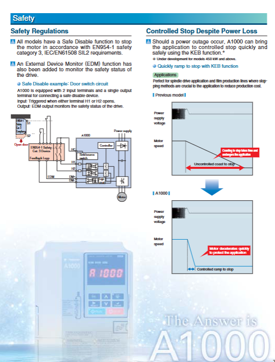
Power failure protection: KEB (Keep Energy Braking) function can use the regenerative energy of the motor to achieve controllable shutdown within 2 seconds after power failure, avoiding safety risks caused by free sliding of the load.
Self tuning and optimization functions
Motor self-tuning: supports rotation self-tuning (high-precision matching of motor parameters), static self-tuning (used when the motor cannot be disconnected from the load), and wire resistance self-tuning (recalibrated after cable length changes).
Load self-tuning: Inertial self-tuning optimizes deceleration performance, ASR gain self-tuning automatically matches frequency reference to ensure stable operation under different loads.
Energy saving self-tuning: Real time optimization of motor voltage and load matching, always maintaining the highest operating efficiency.
Energy saving control technology
Induction motor energy saving: dynamically adjust the output voltage through Energy Saving control, automatically optimize according to speed and load, and reduce no-load losses.
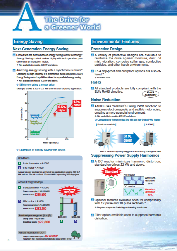
Energy saving synchronous motor: Paired with the EMR1 series ultra efficient synchronous motor, the efficiency is improved by 8.2% -13% compared to traditional induction motors, and the application effect of fans/pumps is particularly significant.
Harmonic suppression: Models of 22kW and above are equipped with built-in DC reactors, reducing the harmonic distortion rate of the power grid from 88% to 40% and minimizing interference with the power grid.
Core advantages of the product
(1) Efficient Energy Saving and Environmental Protection
Quantitative energy-saving effect
Case reference: 100 3.7kW motors are used for HVAC fan systems, operating 365 days a year, with an electricity cost of 0.15 USD/kWh.
Induction motor+ordinary frequency converter: Annual power consumption of 1903100kWh, electricity cost of $285500.
IPM motor+A1000 energy-saving control: Annual power consumption of 1754600kWh, electricity cost of $263200.
Annual electricity savings of $22300, reducing CO2 emissions by 82.4 tons (calculated based on 0.555kg CO2 per 1kWh).
Environmental Design Details
Noise suppression: Swing PWM technology reduces electromagnetic noise and motor operation noise, which is 23.3% lower than previous generation products.
Material compliance: The entire series complies with the RoHS directive, is lead-free and halogen-free, and uses 100% recycled paper and soy ink to print documents.
(2) Safe, reliable, and durable
Security protection system
Functional safety: The Safe Disable function achieves safe shutdown through dual input terminals (H1/H2), complying with EN954-1 Cat.3 and IEC/EN61508 SIL2 standards; EDM (External Device Monitor) function monitors security status in real-time.
Electrical protection: It has comprehensive protection against overcurrent, overvoltage, undervoltage, overload, overheating, grounding faults, etc. When the output current exceeds 200% of the rated overload value, it will immediately shut down.
Environmental adaptation: Provides IP54 dust-proof and drip proof options, supports moisture-proof, dust-proof, oil mist proof, and corrosion-resistant gas design, and is suitable for harsh industrial environments.
Long lifespan and low maintenance
Design lifespan: Key components such as cooling fans, capacitors, relays, IGBTs, etc. have undergone rigorous screening and are designed to have a lifespan of 10 years in an environment of 24 hours, 80% load, and 40 ℃.
Maintenance warning: Built in performance life monitoring function, real-time tracking of cooling fan (LT-1), capacitor (LT-2), surge suppression relay (LT-3), IGBT (LT-4) status, and early output of maintenance signals.
Convenient maintenance: The detachable terminal block supports parameter backup, and there is no need to rewire or set up when replacing the frequency converter; The cooling fan, operator, and other components can be quickly disassembled and replaced.
(3) Convenient operation and flexible configuration
Programming and configuration tools
DriveWorksEZ: a visual programming software that supports drag and drop creation of custom control sequences and detection functions, without the need for complex code writing.
Application Presets: Built in 8 types of application presets for fans, pumps, conveyors, cranes, etc., with one click automatic configuration of core parameters, greatly reducing debugging time.
Operator: Standard LED operator, optional LCD operator (JVOP-180), supports parameter copying and remote operation, equipped with 1m/3m extension cable.
Parameter Management and Migration
Local management: The operator supports parameter copying, and the terminal block has a built-in parameter backup function, ensuring that parameters are not lost after power failure.
Remote management: By using the USB copying unit (JVOP-181) or DriveWizard Plus software, multiple frequency converter parameters can be quickly copied and migrated; Supports RS-422/485 (MEMOBU/Modbus) communication with a maximum baud rate of 115.2kbps.
Flexible installation and layout
Compact design: The 400V 75kW model is 55.4% smaller than the previous generation F7 series, and the 200V 3.7kW synchronous motor is 64% smaller than the induction motor.
Installation method: Supports parallel installation (18.5kW and below), models without heat sinks (upcoming), and external heat sink installation, suitable for different control cabinet space requirements.
Applicable scenarios and selection schemes
(1) Main application areas and adaptation strategies
Application scenario core requirements A1000 adaptation advantages recommended configuration
Crane/winch high starting torque, motor switching, safe and reliable 200% starting torque, Motor 2 Switch function Safe Disable、 Maintenance monitoring overload mode (C6-01=0), closed-loop vector control, braking resistor unit
Energy saving control for fans/pumps, low noise, and stable operation Swing PWM、 Variable frequency jump (to avoid resonance), light load mode (C6-01=1), V/f control, PID control
Smooth operation of conveyor, fast braking, long-life overexcitation deceleration, torque ripple suppression, maintenance warning open-loop vector control, application preset (Conveyor), 24V control power option
Metal processing/machine tool power-off controllable, overvoltage suppression, high-precision KEB function, overvoltage suppression, zero servo control closed-loop vector control, pulse sequence input/output, braking unit
HVAC system energy-saving, communication compatibility, multi motor control energy-saving control, LONWorks communication options, multi-step speed control light load mode, PID control (including sleep function), remote monitoring
(2) Key parameters for selection
Rated mode selection
Normal Duty: C6-01=1, overload capacity of 120%/60s, capable of driving motors larger than its rated capacity, suitable for square law loads such as fans and pumps.
Heavy Duty: C6-01=0 (default), overload capacity of 150%/60s, suitable for constant torque loads such as cranes, conveyors, compressors, etc.
Motor capacity matching
Induction motor: The rated output current of the frequency converter is ≥ the rated current of the motor.
Synchronous motor: Motor code (E5-01) needs to be set to ensure parameter matching. PM motor adaptation support is being developed for models of 450kW and above.
Suggestions for peripheral selection
|Peripheral type | Applicable scenario | Recommended model|
|Braking resistor | Quick stop requirement | ERF-150WJ series (3% ED), LKEB series (10% ED)|
|Noise filter | Electromagnetic interference sensitive environment | LF series (output side), LNFD series (input side)|
|Communication Card | Industrial Network Integration | SI-P3 (PROFIBUS-DP), SI-C3 (CC Link), SI-S3 (CANopen)|
|Operator | Remote operation requirements | JVOP-180 (LCD), WV001/WV003 (extension cable)|
|Maintenance Tools | Multi Device Management | JVOP-181 (USB Copy Unit), DriveWizard Plus Software|