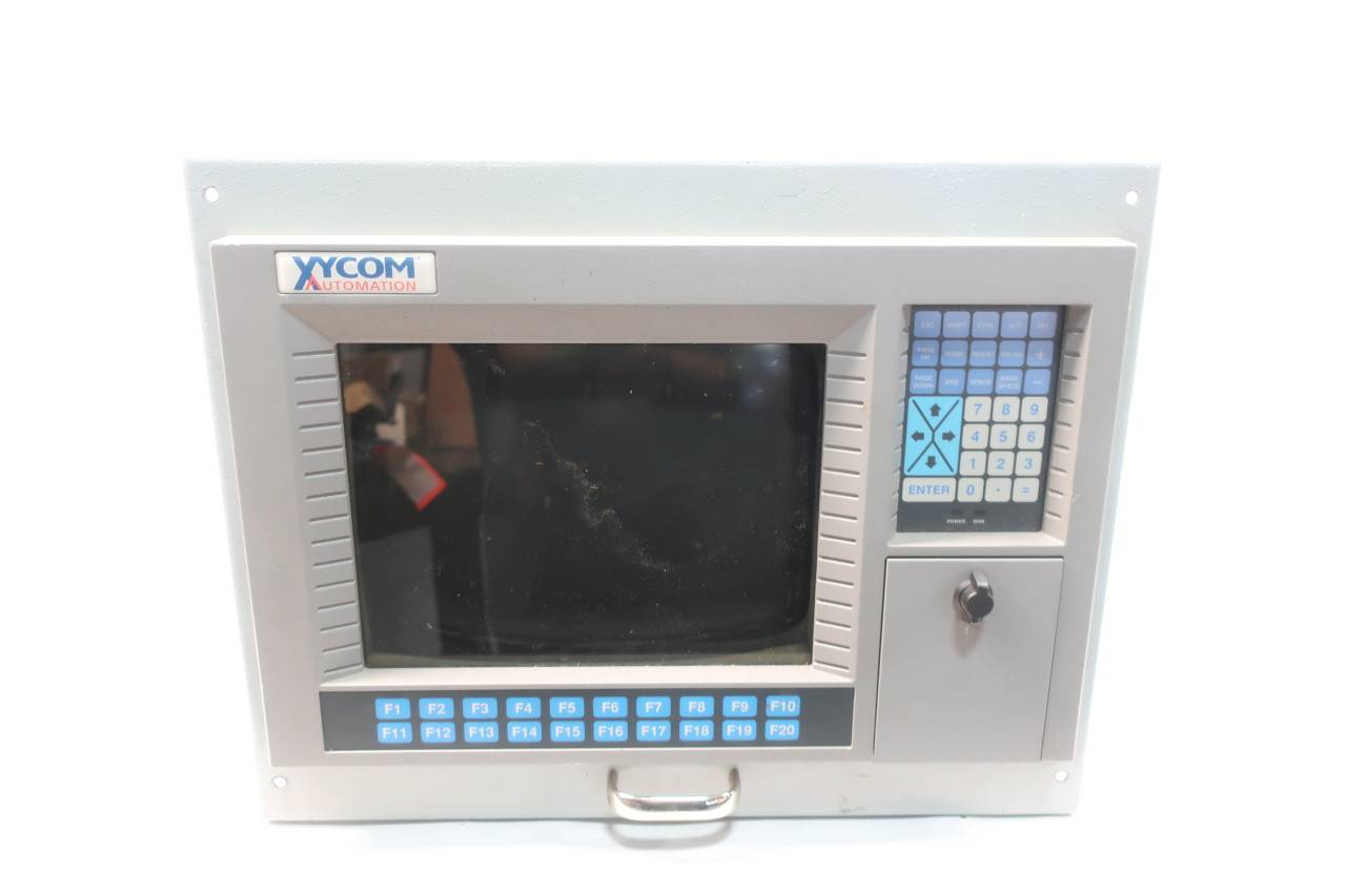
XYCOM XVME-957 VMEBUS Mass Storage Subsystem
Product overview
XVME-957 Mass Storage Sub-system
Provides a high-capacity IDE hard disk drive and a 1.44 Mbyte 3.5″ floppy disk drive in a single VMEbus slot. Designed to be compatible with Xycom’s VME PC/AT processors. Form Factor: 6U (Double)
The XYCOM XVME-957 VMEBUS Mass Storage Subsystem (without hard drives) is designed to meet the demand for large capacity, high-speed data storage in industrial environments. It abandons traditional hard disk storage media and adopts more advanced storage technologies, such as flash memory storage, solid-state storage arrays, etc., to achieve efficient storage and fast reading of data. This subsystem is connected and communicates with other devices (such as industrial computers, controllers, etc.) through the VMEBUS bus, and can quickly and stably transmit data. It can be widely used in data recording of industrial automation production lines, video storage of industrial monitoring systems, data acquisition and storage of scientific research, and other scenarios, providing users with efficient and reliable data storage services.
Core Features
(1) Advantages of No Hard Disk Storage Technology
High reliability: The design without a hard drive avoids the risk of failure caused by mechanical components such as magnetic heads and motors in traditional hard drives, such as wear and tear on the hard drive read/write heads and scratches on the disk, greatly reducing the probability of hardware failure. Flash storage or solid-state storage arrays, which have no mechanical structure, have the characteristics of earthquake resistance and impact resistance. Even in industrial sites with large vibrations and harsh environments, they can ensure the stability and integrity of data storage, effectively reduce the risk of data loss caused by storage device failures, and improve the reliability of industrial system operation.
High speed data read and write: Using advanced storage chips and optimized storage algorithms, the data read and write speed far exceeds traditional hard drives. The sequential read speed can reach several hundred MB per second, and the sequential write speed can also reach a high level, such as 100MB/s or more, which can quickly store and read large amounts of data. In industrial automation production lines, various types of data related to equipment operation, such as high-frequency data collected by sensors, can be recorded in real time and quickly; In video surveillance systems, high-definition video images can be stored smoothly to ensure the integrity and continuity of monitoring data.
Low power consumption and long lifespan: Compared to traditional hard drives, non hard drive storage has lower power consumption, which can reduce overall system energy consumption and lower operating costs. At the same time, flash storage and other media have a long service life and can withstand tens of thousands or even more erase and write operations, effectively extending the service life of the storage subsystem, reducing equipment replacement frequency, and lowering maintenance costs.
(2) Characteristics of VMEBUS bus
High speed data transmission: The VMEBUS bus has high-speed data transmission capability, with a maximum data transmission rate of up to 40MB/s, which can meet the requirements of a large number of storage subsystems for data transmission speed. In industrial environments, the collected data can be quickly transmitted to the storage subsystem for storage, or read from the storage subsystem and transmitted to other devices for processing, ensuring efficient circulation of data within the system.
Stable and reliable communication: The communication protocol based on the VMEBUS bus has high stability and reliability, and can maintain stable data transmission in complex industrial electromagnetic interference environments, reducing data transmission errors and losses. Through the electrical isolation and signal conditioning technology of the bus, the anti-interference ability of the system is effectively enhanced, ensuring the accuracy and stability of communication between the storage subsystem and other devices.
Good scalability: The VMEBUS bus architecture supports modular design, and the XVME-957 storage subsystem can be easily combined and expanded with other VMEBUS bus modules. Users can add storage capacity modules, data processing modules, etc. according to their actual needs, and flexibly build industrial storage systems that meet different scales and functional requirements.
(3) Large capacity storage capability
Despite adopting a diskless design, the XVME-957 still has powerful storage capacity expansion capabilities for a large number of storage subsystems. By integrating multiple storage chips or adopting storage array technology, storage capacity configurations ranging from tens of GB to several TB or even higher can be achieved, meeting the diverse needs of data storage capacity in different industrial application scenarios. Whether it’s small-scale industrial data recording or large-scale video surveillance data storage, it can be easily handled.
(4) Data management function
Data redundancy and backup: Supports solid-state storage implementation of data redundancy technologies, such as RAID (Independent Redundant Disk Array) technology, which can store the same data in multiple storage units through data mirroring, striping, and other methods. When a storage unit fails, data can still be obtained from other redundant storage units to ensure data security and availability. At the same time, it has data backup function, which can regularly back up important data to other storage devices or the cloud, further improving data security.
Data encryption: To protect the security and privacy of industrial data, this storage subsystem supports data encryption function and uses advanced encryption algorithms to encrypt stored data, preventing illegal theft or tampering of data during storage and transmission. Only users with the correct key can access and decrypt data, ensuring the confidentiality of industrial data.
Data indexing and retrieval: Built in efficient data indexing mechanism, which can quickly index and classify stored data, making it convenient for users to conduct data retrieval. Users can quickly locate and retrieve the required data through various conditions such as keywords, timestamps, and data types, improving data query efficiency and facilitating industrial data analysis and decision-making.
Application scenarios
(1) Industrial automation production line
In industrial automation production lines such as automobile manufacturing and electronic equipment production, the XVME-957 mass storage subsystem (without hard drives) can store various data during the operation of production equipment in real time, such as equipment operating parameters (temperature, pressure, speed, etc.), production quantity, product quality inspection data, etc. By storing and analyzing this data, optimization management of the production process can be achieved, production efficiency can be improved, and product quality can be guaranteed. At the same time, the high reliability of the hard disk free design can avoid the loss of production data due to storage device failures, ensuring the continuous and stable operation of the production line.
(2) Industrial monitoring system
In the field of industrial monitoring, this storage subsystem can be used to store high-definition video monitoring images, sensor monitoring data, etc. Its high-speed data read and write capabilities can smoothly store real-time video streams, and its shock resistant and impact resistant characteristics without a hard disk design enable it to work stably in complex industrial environments. Through data redundancy and backup in the data management function, the security of monitoring data can be ensured, providing reliable data support for industrial safety monitoring and accident tracing.
(3) Scientific research and data collection
In fields such as scientific research experiments, geological exploration, and meteorological monitoring, it is necessary to collect and store a large amount of experimental and monitoring data. The large capacity storage capability and high-speed data read and write characteristics of the XVME-957 mass storage subsystem (without hard disk) can meet the data storage needs in these fields. At the same time, its data management function can facilitate researchers to classify, retrieve, and analyze data, improving research efficiency.
(4) Energy Management System
In energy industries such as electricity, oil, and natural gas, this storage subsystem can be used to store various data during energy production, transmission, and consumption processes, such as voltage, current, and power data of the power system, flow and pressure data of oil pipelines, etc. By storing and analyzing this data, it is possible to achieve optimized management of the energy system, improve energy utilization efficiency, and ensure the safety and stability of energy supply.
Precautions for use
(1) Installation and wiring
**
When installing the XVME-957 mass storage subsystem, ensure that the VMEBUS bus chassis is powered off, strictly follow the steps in the installation manual to correctly insert the storage subsystem into the corresponding VMEBUS slot, ensure good contact, and avoid bus communication failures caused by improper installation.
When connecting data cables and power cables, use cables that comply with the VMEBUS bus standard, and pay attention to cable shielding and grounding to prevent electromagnetic interference from affecting data transmission. Ensure that the power supply voltage is consistent with the requirements of the storage subsystem, the connection is secure, and avoid equipment damage caused by power issues.
(2) Parameter configuration and software settings
Before use, configure the storage subsystem parameters through the accompanying management software, including storage capacity allocation, data redundancy mode setting, data encryption key configuration, etc. Carefully check the parameter settings to ensure they meet the actual application requirements and avoid affecting the normal operation of data storage and management functions due to parameter errors.
Regularly update the firmware and management software of the storage subsystem to obtain the latest features and performance optimizations, while fixing potential security vulnerabilities and software defects. During the update process, strictly follow the operating instructions to avoid system failures caused by improper operation.
(3) Environmental requirements
The storage subsystem should be installed in a dry and well ventilated environment to avoid the impact of high temperature and humidity on equipment performance and lifespan. The working temperature range is generally -20 ℃ to+60 ℃, and the storage temperature range is -40 ℃ to+85 ℃, ensuring that the ambient temperature is within the allowable range of the equipment.
Stay away from strong electromagnetic interference sources, such as large motors, transformers, and other equipment, to prevent electromagnetic interference from affecting the data storage and communication functions of the storage subsystem. If it is unavoidable to use in strong electromagnetic environments, electromagnetic shielding measures can be taken, such as using a shielded chassis.
(4) Maintenance and upkeep
Regularly check the working status of the storage subsystem, view device operating parameters, error logs, and other information through management software, and promptly identify potential problems. Check if the VMEBUS bus connection is loose and if the cables are damaged. If there are any issues, promptly address them.
Although the absence of a hard drive design reduces the probability of hardware failure, it is still necessary to regularly clean the storage subsystem by using a clean brush or compressed air to clean the dust on the surface of the equipment and the heat dissipation holes, ensuring good heat dissipation of the equipment and preventing performance degradation or failure due to poor heat dissipation.