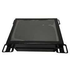
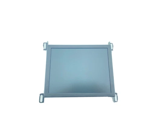
Call us 24/7uaedcs@163.com
Welcome to the official website of CNIACS Automation Technology Co., Ltd!
Call us 24/7uaedcs@163.com

AB Cat. No.1771-IVN DC (10-30V) Input Module

Pre-Installation Notes:
Compatibility: This module is a source input and needs to be paired with a sinking current output for the B-Series 1771 I/O chassis, and can be used with a variety of processors, such as PLC-2/20, PLC-3, etc., see the processor compatibility chart. Cannot be installed in the same I/O chassis as the 1771-IX thermocouple module, but can be used in a common chassis with the 1771-IXE thermocouple module.
Input Filtering: Modules are equipped with input filtering to reduce the effects of voltage transients caused by contact bounce and electrical noise, as listed at the end of the document.

Installation Procedures:
Static protection: the module is sensitive to static electricity, before installation, you need to touch a grounded object to discharge static electricity, avoid touching the backplane connectors, pins and internal circuit components, when not in use, placed in a static shielding bag.
Chassis keying: Use the plastic keying tape supplied with the I/O chassis and place the tape between 14 – 16 and 30 – 32 on the chassis backplane to ensure proper module installation.
Module Installation: Insert the module board against the top and bottom card rails of the chassis, press firmly to make a tight connection to the backplane connector, and then swing the module locking latch down to secure it.

Wiring Connections: Connect the wiring through the 1771-WN field wiring arm, making sure to disconnect the power before wiring, and paying attention to the polarity of the power supply to avoid damaging the module by reversing the wiring or connecting it to AC voltage. Each module incorporates 2 complete modules (32 inputs) in each I/O chassis slot, see Module Input Terminal Assignment table for wiring correspondence.
Status Indicators: There are 32 status indicators on the front panel of the module, which correspond to the control status of the inputs and light up when the corresponding inputs have voltage.
Module Specifications:
| Description | Values |
| Number of Inputs per Module | 32 | Module Location | 1771 | 1771 | 1771 | 1771 | 32
| Module Location | 1771-A1B to -A4B I/O Enclosures |
| | Input Voltage Range (+dc)| 10 – 30V dc|
| Input Voltage Range (+dc)|10 – 30V dc| Nominal Input Current | 4.5mA@(+dc – 10V dc)| Min.
| Minimum Off-State Current | 1.7mA @ (+dc – 5V dc)| | Nominal Input Current | 4.5mA @ (+dc – 10V dc)|
|Maximum Off-State Voltage |(+dc – 5V dc)|

Input Impedance |2.2K| Input Signal Delay |Low
| Input Signal Delay | Low to High Propagation: 6ms (±2ms); High to Low Propagation: 6ms (±2ms)| | Power Consumption | 15ms max.
| Power Consumption | 15.6W max; 1.5W min.
| Thermal Dissipation | 53.3 BTU/hr max; 5.1 BTU/hr min| | Backplane Current | 5.5 BTU/hr max; 5.1 BTU/hrmin
| Backplane Current | 280mA at 5V dc max.
Isolation Voltage | 1500V ac RMS| | Wire Size | 14 gauge
| Conductor Gauge | 14 gauge stranded wire (max); 3/64 inch insulation (max); Category 1| | Environmental Conditions | Operating Temperature | 5V dc max; 5 BTU/hr min
| Environmental Conditions | Operating Temperature 0 – 60 ∘C (32 – 140 ∘ F); Storage Temperature – 40 – 85 ∘C (- 40 – 185 ∘ F); Relative Humidity 5 – 95% (non-condensing)|
| Keyed Positions | Between 14 – 16 and 30 – 32 | Field Wiring Arm | 1771-WN
| Field Wiring Arms | 1771-WN| Keyed Positions | Between 14 – 16 and 30 – 32
| Field Wiring Arm | 1771-WN| | Wiring Arm Screw Torque | 7 – 9 in-lb
Critical Issues:
Which module cannot be installed in the same I/O chassis as the 1771-IVN module?
Answer: The 1771-IVN module cannot be installed in the same I/O chassis as the 1771-IX thermocouple module.
What is the input signal delay for this module?
Answer: The input signal delay for this module is 6ms (±2ms) for low to high propagation and 6ms (±2ms) for high to low propagation.
What is the input voltage range of the 1771-IVN module?
Answer: The input voltage range for the 1771-IVN module is 10 – 30V dc.

Input Filter Characteristics
Functional role: Input filtering is mainly used to limit the impact of voltage transients caused by contact bounce and electrical noise on the module. In industrial environments, the frequent starting and stopping of electrical equipment, motor operation, etc. may generate electrical noise, while the contact bounce of mechanical contacts may also cause voltage fluctuations. These disturbances, if left untreated, may cause the module to misinterpret the input signals, affecting the normal operation of the system. 1771-IVN module’s input filtering feature effectively reduces these disturbances and ensures that the module accurately recognises the input signals.

Importance: This filtering feature is critical to the stable operation of the module. It ensures that the module can accurately acquire input signals in complex electromagnetic environments, avoiding erroneous signals caused by voltage transients, and thus guaranteeing the stable and reliable operation of the entire control system. In factories with a large number of electrical equipment, all kinds of electrical noise are intertwined, and if the module does not have good filtering characteristics, its input signal will be easily interfered with, resulting in system control deviation, while the input filtering function of the 1771-IVN module can effectively reduce this risk.

1771-IBN | Allen-Bradley | DC (10-30V) Input Module Supplier | Amikon

AB 1771-IFE A/B/C Analog Input Module

Preparation before installation:
Static electricity protection: the module is sensitive to static electricity, touch grounded objects, wear a wrist strap when operating, avoid touching the backplane connectors and internal circuit components, and place it in a static shielding box when not in use.
Directive Compliance: CE marked, compliant with EU EMC and Low Voltage Directives, meets relevant standards.

Compatibility: Can be used in 1771 I/O chassis, but not with 1771-AL PLC – 2/20 or 2/30 local adapters.
Power Calculation: Module draws 500mA from the 1771 I/O power supply and needs to calculate the total power in the chassis to prevent overloading.
Module Positioning: Can be installed in slots other than the leftmost slot (reserved for PC processor or adapter modules) with care to avoid electromagnetic interference.
Installation Procedure:

Jumper Setting: If replacing an A or B series module, set the A/B analogue jumper from POS G to POS E; select the input type (voltage or current) by configuring the jumper, but all inputs must be either single-ended or differential and cannot be mixed .
Module Installation: Smoothly insert the module into the chassis rails after power is removed, secure the chassis latch and locking lever, and connect the 1771-WG wiring arm.
Wiring Connection: Connect the I/O devices, note the difference in connection between single-ended and differential inputs, avoid mixing 2-wire and 4-wire transmitter inputs, the sensor cable should be shielded and grounded.

Grounding operation: The foil shield and drain wire of the shielded cable are grounded at one end only, connected to the chassis mounting bolts, and insulated at the other end.
Module Configuration: A wide range of parameters can be configured via the Block Transfer Write command, such as 7 input voltage or current ranges, data format (BCD or binary), real-time sampling (100 ms – 3.1 sec selectable), digital filtering (0.00 BCD – 0.99 BCD),** scaling (max range ±9999 BCD)**, etc. The default configuration is 1 – 5V dvd. Default configurations are 1 – 5V dc or 4 – 20mA, BCD format, no real-time sampling, etc.

Troubleshooting: There are green RUN and red FAULT indicators on the front panel of the module, and faults can be judged by the status of the indicators and the status bits in the BTR file. If RUN blinks and FAULT is off, it means waiting for configuration; if RUN is off and FAULT is on, it may be a hardware failure.
Module specification:
| Description | Values
|—|—| Inputs per module | 16
| Inputs per module | 16 single-ended; 8 differential low | Module Position | 1771

| Input Voltage Range |+1 to +5V dc, 0 to +5V dc, etc. | Input Current Range |+1 to +5V dc, 0 to +5V dc, etc.
| Input Current Range +1 to +5V dc, 0 to +5V dc, etc. | Input Voltage Range +1 to +5V dc, 0 to +5V dc, etc.
Input Current Range |+4 to +20mA, 0 to +20mA, etc. | Resolution | 12-bit binary (12-bit plus sign bit for bipolar range)
Accuracy | 0.1% of full scale range @ 25°C| | Linearity | ±1% of full scale range @ 25°C
| Linearity |±1 LSB| | Repeatability |±1 LSB| | Repetition
| Repeatability |±1 LSB| | Isolation Voltage
| Isolation Voltage | Meets or exceeds UL Standard 508 and CSA Standard C22.2 No. 142.
| Input Overvoltage Protection | Voltage Mode 200V, Current Mode 8V| | Input Overcurrent Protection | Voltage Mode 200V, Current Mode 8V
Input Overcurrent Protection |30mA| Common Mode Voltage |±0.5V, Current Mode 8V
Input Overcurrent Protection |30mA| Common Mode Voltage |±14.25V
| Input Impedance | Voltage range >10 megohms; Current range 250 ohms | Common Mode Rejection Ratio
| Common Mode Rejection Ratio | 80 db, dc – 120Hz | Common Mode Voltage | ±14.25V | Input Impedance
Current Requirement | 500mA @ +5V (I/O chassis backplane)| | Power Consumption | 2.5mA @ +5V (I/O chassis backplane)
Power Consumption | 2.5 Watts (Max) | Thermal Dissipation | 8.5 Watts (Max)
| Thermal Dissipation | 8.52 BTU/hr (max)| | Power Consumption | 2.5 Watts (max)
| Unscaled Output | Polarity Range 0000 to +4095; Bipolar Range – 4095 to +4095|
| Engineering Units Output | ±9999 (optional scaling)| | Internal Scan Rate | 8
| Internal Scan Rate | 8-way differential unfiltered 13.7ms; 16-way single-ended unfiltered 27.4ms | Environmental Conditions | Operating Temperature
| Environmental Conditions | Operating Temperature 0 – 60 °C 0 – 60∘Operating Temperature 0 – 60
Operating Temperature 0 – 60 ∘ C Operating Temperature 0 – 60 ∘ C; Storage Temperature – 40 – 85 85° C
Relative humidity 5 – 95% (non-condensing) | Conductor gauge | 14 gauge (non-condensing)
| Conductor Gauge | 14 gauge (2mm 2mmStranded Wire (Max)3/64inch (1.2mm) insulation (maximum); Category 2| Keyed Positions | Between 10 – 12, 24 – 26
| Keyed Positions | Between 10 – 12, 24 – 26 | Wiring Arms
| Junction Arm | Catalog Number 1771-WG
| Junction Arm Screw Torque | 7 – 9 in-lb | Keyed Positions | 10 – 12, 24 – 26
| Agency Approvals | Class 1 Div 2 Hazardous; CE marking (applies to directives)| | Series Differences: A, B, and C
Series Differences: The A, B, and C series modules differ in indicator lights, input data handling, default scaling, block transfer length, configuration plugs, compatibility, calibration procedures, and agency approvals. For example, the A and B series modules have a green run indicator that is always on at power-up, while the C series modules blink until they are configured to receive BTW; the A and B series modules input data is clamped at the range endpoints, while the C series modules can return data both above and below the range endpoints.

Key Issues:
How are 1771-IFE A/B/C modules installed to prevent static discharge?
Answer: Discharge static electricity by touching a grounded object; wear an approved wrist strap grounding device; do not touch the backplane connectors, pins, and internal circuitry components of the module; use an antistatic workbench if available; and place the module in a static-shielded box when not in use.

How are the module’s input ranges and data formats configured?
Answer: Input ranges are configured via Word 1 and Word 2 of the Block Transfer Write command, with a 2-bit setting for each channel and a choice of 7 voltage or current ranges; data formats are set via Bits 09 – 10 of Word 3, with a choice of BCD, Binary Complement, or Symbol Amplitude Binary formats, typically BCD for PLC-2 and Binary Complement for PLC-3 and PLC-5.

What is the difference between Series A, B, and C modules in terms of indicator display?
Answer: Series A and B modules have a green run LED that comes on and stays on at power up and provides only 3 digits of diagnostic information; Series C modules have a green run LED that blinks at power up and stays on until a configuration BTW is received and provides 6 digits of diagnostic information representing 6 possible faults.

USED ALLEN BRADLEY 1771-IFE/C ANALOG INPUT MODULE 1771IFEC - SB ...

AB Analog Input Module Cat. No. 1771-IFE

Module Overview: The 1771-IFE Analogue Input Module is an intelligent block transfer module that interfaces with block transfer capable Allen-Bradley programmable controllers to enable data interaction between analogue input signals and the controller. It is a single-slot module that requires no external power supply (passive sensors require user-supplied loop power) and is capable of processing 16 single-ended or 8 differential analogue inputs and converting them to a specified data format for transmission to the processor.

Installation Procedure:
Pre-installation Preparation: Before installation, calculate the power requirements of all modules in the chassis to avoid overload, determine the location of the modules in the I/O chassis (any slot except the leftmost slot), and key the backplane connectors.

Static protection: Wear an anti-static wrist strap or touch a grounded object during operation, avoid touching the backplane connector pins, and place the module in a static-shielding bag when not in use.
Wiring operation: Connect the 1771-WG wiring arm, single-ended inputs and differential inputs have different connection methods, and the analogue input signal should be within ±14.25V, unused channels should be shorted to the common terminal of the module. The module defaults to a 1 – 5V DC voltage input, which can be changed via the configuration plug.

Programming points:
Block Transfer Programming: The module communicates with the processor via a bi-directional block transfer, the block transfer write command is used to initialise the configuration, the rest of the time it is mainly in block transfer read mode.
Examples of programming for different processors: PLC-2 is programmed with the note that read and write instructions cannot be enabled at the same time; PLC-3 uses a binary file for storing module related data; PLC-5 uses a separate control file and is conditional on an enable bit.
Scan Time: The scan time refers to the time it takes for the module to read the input channels and put the new data into the data buffer, which is related to the module configuration, e.g. 12.5ms for 8 differential inputs without filtering, 25ms for 16 single-ended inputs without filtering.

Module Configuration:
Input Range Selection: 5 types of voltage or 3 types of current input ranges can be configured, set by the specified word of the Block Transfer Write command.
Other Configuration Options: Includes selection of input type (single-ended or differential), data format (BCD or binary, etc.), digital filtering, real-time sampling and scaling, and other functions.

Data Reading and Diagnostics:
Data reading: Transfer module status and data to processor data table through block transfer read programming, data contains diagnostic bits, input values and other information.
Troubleshooting: The module reports faults through indicators and status bits, e.g., the red FAULT indicator lights up to indicate a fault, and the type of fault can be determined according to the diagnostic bits.

Calibration operation:
CALIBRATION TOOLS: Calibration requires a digital voltmeter (e.g., Keithley 191 or Fluke 8300A), a calibration tool (p/n 35F616), potentiometer sealant, industrial terminals (1770 – T3, etc.), and a backplane expansion card (1771 – EZ).
Calibration procedure: Adjust the 10V reference voltage, then zero the input offset. The module must be powered on for 30 minutes before calibration and cannot be calibrated in the operating system.
Technical specifications: The module has various technical specifications, such as input voltage ranges from +1 to +5V dc, current ranges from +4 to +20mA, 12-bit binary resolution, 0.1% of full scale range @ 25 °C, and so on.

Key Issues:
What are the key things to keep in mind when installing 1771-IFE modules?
Answer: Installation requires calculating the power requirements of all modules in the box to avoid overloading; select a location other than the leftmost slot for installation; key the backplane connector; protect against static electricity and avoid touching the backplane connector pins; when connecting the 1771-WG wiring arm, pay attention to the connection of single-ended and differential inputs to ensure that the analogue input signals are in the range of ±14.25V, and that unused channels are shorted to the module common; the module’s default 1 – 5V DC voltage inputs can be configured as required. Unused channels are shorted to the common of the module; the module defaults to a 1 – 5V DC voltage input, which can be changed as required by configuring the plug.

How is the module programmed differently on different processors?
Answer: In PLC-2 programming, it is important to note that read/write commands cannot be enabled at the same time, and specific memory bits are used to control the block transfer order; PLC-3 uses a binary file to store module related data, and the industrial terminal will prompt for the creation of a control file; and PLC-5 uses a separate control file, and conditions each rung with an enable bit rather than a completion bit.

How do I calibrate the 1771-IFE module?
Answer: Calibration requires a digital voltmeter, calibration tool, potentiometer sealant, industrial terminal and backplane expansion card. First, adjust the 10V reference voltage, turn off the power of the processor and I/O chassis, insert the module into the expansion card and then into the chassis, connect the voltmeter and then adjust potentiometer R64 to make the TP1 voltage 10.0000V (±.0002V max.); then, zero the input offset, turn off the power, move jumper E1, connect the voltmeter, turn on the power and adjust potentiometer R63 to make the TP2 voltage 0.0000V (±.0002V max.). 0.0000V (±0.0002V max.), then remove the power supply and restore jumper E1 to its default position.

Application Scenarios
Industrial automation production: In the manufacturing production line, it can be connected to a variety of devices such as temperature sensors, pressure sensors, flow sensors, etc. to collect analogue signals in the production process. Take an automobile manufacturing plant as an example, in the painting workshop, the module collects temperature and humidity sensor signals, which are converted and transmitted to the programmable controller, which accurately regulates the painting environment to ensure stable coating quality; in the assembly workshop, it monitors the pressure and position sensor signals of the robotic arm to ensure the accuracy of parts assembly and the safety of the equipment, and to improve the production efficiency and quality of the products.

Process control system: Suitable for chemical, electric power, metallurgy and other process control scenarios. In chemical production, connect flow, pressure, temperature, composition analysis and other sensors to collect real-time analogue signals of process parameters in the reactor. The module converts the signals into digital format and transmits them to the controller, which adjusts valve openings, pump speeds and other actuators according to preset parameters and algorithms to realise automated control of the production process, ensure a stable and efficient production process, reduce production costs and reduce human errors.

Environmental monitoring and control system: play an important role in intelligent buildings, environmental monitoring systems. In intelligent buildings, temperature and humidity sensors, light sensors, air quality sensors, etc. are connected to collect analogue signals of indoor environment and transmit them to the central control system. The system automatically adjusts air conditioning, ventilation, lighting and other equipment based on the data to create a comfortable, energy-efficient indoor environment. In the field of environmental protection monitoring, it is used to collect analogue signals such as air pollutant concentration and water quality parameters to achieve real-time monitoring and early warning of environmental quality and provide data basis for environmental protection decision-making.

Testing and experimental equipment: in all kinds of test benches and experimental equipment, it is used to collect analogue data in the experimental process. In electronic equipment testing, connecting voltage, current, power and other sensors, real-time monitoring of electrical parameters in the testing process, to provide data support for product performance evaluation and quality testing. In scientific research experiments, it collects analogue signals of various physical and chemical quantities to help researchers accurately record and analyse experimental data and promote the progress of scientific research.

Allen-Bradley 1771-IFE/C Analog Input Module for sale online | eBay

AB PLC-5 1771 to ControlLogix 1756

Product Overview:This document is a selection guide for the AB I/O Wiring Conversion System for converting PLC-5 1771 I/O to ControlLogix 1756 I/O without removing field wires, reducing the risk of wiring errors. The system includes conversion modules, cables, and conversion mounting components.

Product Selection:
Conversion Mounting Kit Selection: To determine the number of 1771 I/O modules, refer to the table to select the appropriate 1492 conversion module, 1756 I/O chassis, and conversion mounting kit, noting the maximum number of slots and chassis width for each kit. For example, the maximum number of I/O slots for 1771-A1B chassis without power supply is 4, the maximum number of I/O slots for 1756-A4 chassis is 3, and the maximum number of converter module slots for 1492-MUA1B-A4-A7 conversion mounting assembly is 4.

I/O Module Selection: When selecting digital, analogue, and high-resolution isolated analogue I/O modules, it is necessary to find the corresponding 1756-compatible module, converter module, and converter cable type according to the 1771 module type. For example, if 1771-IA is converted to 1756-IA16, the conversion module is 1492-CM1771-LD007 and the conversion cable is 1492-C005005XE. The

specific selection information is shown in the following table:
| Module Types | 1771 Modules | 1756 Modules | Conversion Modules | Conversion Cables |
|—|—|—|—|—|—|
| Digital Inputs | 1771-IA| 1756-IA16| 1492-CM1771-LD007| 1492-C005005XE|
| Digital Output | 1771-OA|1756-OA8E|1492-CM1771-LD014|1492-CONACAB005U|
| Analogue Input | 1771-IFE (differential current)| 1756-IF16|1492-CM1771-LA002|1492-CONACAB005D|
| Analogue Output | 1771-OFE1 (Voltage)| 1756-OF6VI| 1492-CM1771-LA003| 1492-CONACAB005E|
| High Resolution Isolated Analogue | 1771-NOC|1756-OF8I| – |1492-CONACAB020N88 etc |
Outline Dimensions: The document gives approximate dimensions in inches and millimetres for different conversion mounting assemblies in combination with the 1756 chassis, including dimensions in inches and millimetres for left-aligned, right-aligned, and centred mounting, to facilitate the design of mounting layouts.

Wiring Diagrams:
Digital Inputs: Provides wiring diagrams for converting a variety of 1771 digital input modules to 1756 modules, detailing pin-by-pin connections and pointing out application considerations such as input delay times, voltage levels, and more.
Digital Outputs: Shows wiring diagrams for converting 1771 digital output modules to 1756 modules, along with key information such as output current limits, fuse configurations, and more.

Analogue Inputs and Outputs: Covers wiring diagrams for converting 1771 analogue input and output modules, highlighting key points such as shield grounding, input and output range configurations, etc.
High Resolution Isolated Analogue: For 1771 high resolution isolated analogue I/O module conversions, wiring diagrams are provided for different connection scenarios and related considerations.
Technical Support and Feedback: Provides resources such as a technical support centre, local technical support phone numbers, direct dial codes, a literature library, product compatibility and a download centre; also gives ways to provide feedback on documentation, a specific form for submitting suggestions, and access to product environmental information on the website.

Key Question:
How do I select the right conversion installation components?
Answer: Determine the number of each type of I/O module in the 1771 I/O chassis, then select the appropriate 1492 conversion module from the table, and refer to the maximum number of I/O slots, chassis width, etc. to select a 1756 I/O chassis with enough I/O slots and a conversion mounting kit with enough slots for conversion modules.

What are the key considerations when converting a 1771-IA module to a 1756-IA16 module?
Answer: Conversion module 1492-CM1771-LD007 and conversion cable 1492-C005005XE are required; 1771-IA module input delays are 24ms (±10ms) on-off, 24ms (±10ms) off-on, 1756-IA16 module is 10ms max on-off (with optional filter) when using this conversion cable. The 1756-IA16 module is rated for 87V – 138V AC and 97V – 138V DC, the 1771-IA module is rated for 79V – 132V AC only.

Wire-free conversion: The I/O conversion process eliminates the need to remove any field wires from the existing swing arm. The conversion module adapts directly to the existing swing arm and transmits the I/O signals to the 1756 I/O module via the conversion module and cables, which greatly reduces the risk of wiring errors, reduces the number of failures caused by wiring errors during system upgrades, and improves conversion efficiency and stability.
Pre-wired design: The cables in the system are pre-wired, with one end connecting to the converter module and the other end being a removable terminal block (RTB). This design simplifies the installation process, saves installation time, reduces labour costs, reduces problems caused by improper wiring on site, and improves overall system reliability.

Flexible mounting components: The base plate of the conversion mounting kit has the same mounting holes and dimensions as the 1771 chassis, eliminating the need for re-drilling and tapping in the control cabinet; the cover plate is equipped with pre-drilled and tapped mounting holes, which allows the 1756 chassis to be mounted in left-aligned, right-aligned, or centre-mounted position, facilitating the installation of different installation spaces and layout requirements, and enhancing the flexibility of system installation.

Comprehensive Conversion Adaptation: A wide range of 1771 I/O modules can be converted to 1756 I/O modules, including digital inputs, digital outputs, analogue inputs, analogue outputs, and high-resolution isolated analogue I/O modules. For different types and models of modules, corresponding conversion modules, cables and detailed wiring methods are provided to ensure the accurate conversion and transmission of all types of signals.

Detailed technical specifications and considerations: Each I/O module conversion is clearly given technical specifications and application considerations. For example, input delay time and voltage level of digital input/output module, shield grounding, signal type assumption, input/output range configuration of analogue input/output module, cable length and terminal connection of high-resolution isolated analogue module, etc., which provide comprehensive technical guidance for users in the process of selecting, installing and using, and guarantee the correct operation of the system.

AB1642 Module Manual MicroLogix 1500

AB1642 Module Manual MicroLogix 1500 & CompactLogix Resolver Interface Module
Modulübersicht: Das Modul 1642 nutzt eine von Allen-Bradley lizenzierte Schnittstellentechnologie und wird direkt in einen Steckplatz in einem MicroLogix 1500- oder CompactLogix-SPS-System eingesteckt. Es kommuniziert über das dem Steckplatz zugewiesene E/A-Register, kann für die Verwendung von zwei Single-Resolver-Sensoren oder einem Dual-Resolver-Sensor konfiguriert werden und kann in bestimmten Konfigurationen die Nachlaufzeit von Kanal 1 überwachen.

Installation des Moduls
Hardware-Installation: Trennen Sie vor der Installation die Stromversorgung, um sicherzustellen, dass das Systemnetzteil über eine ausreichende Stromkapazität verfügt, setzen Sie das Modul ein und befestigen Sie es an den Schienen, bringen Sie die Endkappe am Modul ganz rechts an, und halten Sie das Modul nicht weiter als 7 Steckplätze von der Stromversorgung entfernt.
Softwarekonfiguration: In einem CompactLogix-System kann eine generische Konfiguration oder eine spezifische Konfiguration für RSLogix 5000 V20 und höher verwendet werden; in einem MicroLogix 1500-System werden Vorgänge im Zusammenhang mit der E/A-Konfiguration im RSLogix 500-Projekt ausgeführt.

Modulspezifikationen: Der Strombedarf beträgt 220mA @5Vdc typisch, 360mA @5Vdc maximal bei kurzgeschlossener Referenzspannung; die Zeiten für die Positionsaktualisierung und die Aktualisierung der Backplane variieren mit der Frequenz der Referenzspannung. Kompatibel mit einer breiten Palette von AMCI-Resolver-Sensoren, einige andere Sensoren können über das RM-Referenzmodul angepasst werden. Mehrere programmierbare Parameter, automatische Datenaktualisierung, Modulprogrammierung durch Programmierzyklen, Programmspeicherung im EEPROM. Betriebstemperatur 0 – 60°C, relative Luftfeuchtigkeit 5 – 95% (nicht kondensierend), Lagertemperatur – 40 – 85°C.

Programmierbare Parameter: Umfasst Parameter wie Anwendungsvoreinstellung, Zählrichtung, Sensor-Fehlerverriegelung, Tachometerreaktion, Deaktivierung von Kanal 2, Referenzspannungsfrequenz, Drehtransformatortyp, Skalenendwert, Voreinstellwerte, Sensortyp und Anzahl der Umdrehungen usw., die zur Konfiguration des Moduls eingestellt werden können und in einem nichtflüchtigen EEPROM gespeichert werden.

Backplane-Programmierung: Die Programmierung erfolgt über Eingangs- und Ausgangsworte unter Verwendung des Handshake-Protokolls zur Steuerung des Empfangs von Programmierdaten. Der Programmierzyklus besteht aus sechs Schritten. Der Programmierzyklus besteht aus sechs Schritten. Die Parameter werden im EEPROM gespeichert und können nur begrenzt oft geschrieben werden. Eingangs- und Ausgangsregister haben in verschiedenen Konfigurationen unterschiedliche Datenformate, und Statuswörter werden zur Anzeige verschiedener Fehler und Statusmeldungen verwendet.

Features of the resolver interface of the 1642 module
Connection characteristics: The 18-pin connector used to connect the resolver has several internal pins with specific functions. For example, pin 1 is located in the upper left corner and pins 1, 2, 15 and 16 are ground pins for connecting to the cable shield and reducing electrical noise interference. The function of pins 3 – 10 varies with the type of resolver. The two R1 and two R2 signals of the module are internally connected to facilitate the signal connection to the resolver and ensure the stability of the signal transmission.

Supported types: Compatible with a wide range of resolvers, it can be used with two AMCI single resolvers (e.g. HT – 20 series, H25 – XX series, HT – 20 – X series), or connected to an AMCI dual resolver (e.g. HTT – 20 – X series) or an Autotech dual resolver (RL210 128 turn). For other types of resolver, support is also possible through the use of the AMCI RM reference module, which significantly extends the range of applications.

Electrical characteristics: The resolver is supplied with a reference voltage which can be selected between 5kHz and 2.5kHz. The default value of 5kHz is suitable for most applications, and a setting of 2.5kHz improves system performance when cable lengths exceed 100ft. Rotary transformer signals are low-voltage, low-power signals, the wiring should follow the A – B wiring guidelines, treated as Category 2 cable, and can not be installed in the same pipeline with the AC power line or high-power AC and DC I/O lines, to avoid electromagnetic interference affecting the signal transmission.

Troubleshooting features: Sensor fault detection is available to detect faults caused by improper wiring, electrical noise, or sensor damage. By default, sensor faults are not latched and fault conditions are automatically cleared when a valid signal is detected. However, if transient faults need to be captured reliably, the Sensor Fault Lockout parameter can be enabled, after which a Clear Error command needs to be sent to clear the fault, making it easier for the user to troubleshoot and handle the fault.

Data Processing Features: Converts and transmits rotary transformer position and speed data to the PLC; for single rotary transformer configurations, position (in counts) and speed (RPM) for channels 1 and 2, as well as stopping time and brake application position data for channel 1. For dual resolver configurations, position data is reported in a specific format that splits the position data into two words for easy processing and storage by the PLC, meeting the data requirements of different control scenarios.

Allen-Bradley CompactLogix 1500 PLC Output Module

AB MicroLogix 1400 Programmable Controllers

AB MicroLogix 1400 Programmable Controllers

WICHTIGE BENUTZERINFORMATIONEN: Halbleitergeräte haben andere Betriebseigenschaften als elektromechanische Geräte, und der Benutzer muss sicherstellen, dass die Geräte ordnungsgemäß verwendet werden. Rockwell haftet nicht für Folgeschäden, die sich aus der Verwendung des Geräts ergeben. Die Beispiele in den Handbüchern dienen nur als Referenz, und die Vervielfältigung des Handbuchinhalts ohne schriftliche Genehmigung ist verboten. In den Handbüchern wird eine Vielzahl von Symbolen verwendet, um die Benutzer an Sicherheitsvorkehrungen zu erinnern.

Produktübersicht: Für den Einsatz in industriellen Umgebungen, für den Einsatz in sauberen, trockenen Räumen (Verschmutzungsklasse 2), mit Stromkreisüberspannungen, die die Klasse II nicht überschreiten (gemäß IEC 60664 – 1), und für wechselstrombetriebene Produkte, die an die Sekundärseite eines Trenntransformators angeschlossen werden müssen.

Beschreibung des Steuergeräts: Detaillierte Beschreibung der Lage und Funktion der einzelnen Teile des Steuergeräts, einschließlich der Kommunikationsanschlüsse, Speichermodule, Benutzerstromversorgung, Eingangs-/Ausgangsklemmenblöcke, Anzeige und Tasten, Batteriefach usw. sowie der Unterschiede in den Eingangs-/Ausgangskonfigurationen der verschiedenen Modelle von Steuergeräten.

Vorsichtsmaßnahmen für explosionsgefährdete Bereiche: Einige Module eignen sich für den Einsatz in explosionsgefährdeten Bereichen der Klasse I, Division 2, Gruppen A, B, C und D sowie in nicht explosionsgefährdeten Bereichen. Beim Einsatz in explosionsgefährdeten Bereichen ist das Einstecken, Abziehen oder Austauschen von Teilen mit Strom verboten, und das Gerät muss in einem geeigneten Gehäuse installiert werden, wobei die Verdrahtung den einschlägigen Normen entsprechen und das angegebene Kommunikationskabel verwendet werden muss.

Montage des Reglers
Allgemeine Vorsichtsmaßnahmen: Für die meisten Anwendungen ist es erforderlich, den Regler in einem Industriegehäuse zu montieren, fern von Störquellen, waagerecht, mit Vorsicht beim Bohren von Löchern für Metallspäne, außerhalb des direkten Sonnenlichts und mit Programmieranschlüssen, die nur vorübergehend verwendet werden dürfen.
Einbaumaße und Abstände: Die Einbaumaße des Reglers und die erforderlichen Abstände zu den Peripheriegeräten sind angegeben.
Montagemethoden: Das Steuergerät kann auf einer DIN-Schiene oder auf einer Schalttafel montiert werden, und die spezifischen Schritte und Werkzeuge, die für jede der beiden Montagemethoden erforderlich sind, werden beschrieben.

Verwendung von Batterien: Der Controller ist mit austauschbaren Batterien ausgestattet. Die LCD-Anzeige zeigt an, wenn die Batterie schwach ist, die Batterie sollte beim Einschalten des Geräts ausgetauscht werden, und die Batterie sollte mit Vorsicht betrieben werden, um Lichtbögen in gefährlichen Bereichen zu vermeiden.
Anschluss von E/A-Erweiterungsmodulen der Serie 1762: Trennen Sie das System von der Stromversorgung, bevor Sie ein Erweiterungsmodul installieren oder entfernen, und befolgen Sie die Anweisungen zum Anschluss des Moduls. Die MicroLogix 1400-Steuerung unterstützt bis zu sieben Erweiterungsmodule der Serie 1762.

Verdrahtung der Steuerung
Verdrahtungslayout und Vorsichtsmaßnahmen: Zeigt das Layout der Eingangs- und Ausgangsklemmenblöcke für verschiedene Steuerungsmodelle und weist auf die Sicherheitsanforderungen für die Verdrahtung in explosionsgefährdeten Bereichen hin, um Lichtbögen und Explosionen zu vermeiden.
Verdrahtungsempfehlungen: Enthält spezifische Empfehlungen für die Verdrahtung, z. B. die Verwendung von Berührungsschutzabdeckungen und die Auswahl geeigneter Klemmen.
Überspannungsschutz und Erdung: Induktive Lasten erfordern einen Überspannungsschutz, Erdung reduziert elektromagnetische Störungen, und die Verdrahtung analoger Kanäle stellt besondere Anforderungen, wie die Verwendung spezieller Kabel und eine ordnungsgemäße Erdung.

Verschiedene Modelle von Eingangs- und Ausgangskonfigurationen von Steuerungen
1766 – L32BWA: Eingangsspannung 100/240V AC, Benutzerspannung 24V DC Diskrete Eingänge umfassen 12 schnelle 24V DC Eingänge und 8 normale 24V DC Eingänge; Ausgänge umfassen 12 Relaisausgänge. Kommunikationsanschlüsse: 1 RS232/RS485-Schnittstelle, 1 Ethernet/IP-Schnittstelle und 1 RS232-Schnittstelle; keine analogen Ein- oder Ausgänge.

1766 – L32AWA: Keine Benutzerspannungsversorgung, Eingangsversorgung nicht erwähnt. Die diskreten Eingänge sind 20 120-V-AC-Eingänge, die Ausgänge sind 12 Relaisausgänge, wiederum keine analogen Ein- oder Ausgänge, und die Angaben zu den Kommunikationsanschlüssen sind nicht detailliert.

1766 – L32BXB: Eingangsversorgung 24V DC, keine Benutzerversorgung. Diskrete Eingänge sind 12 schnelle 24-V-Gleichstrom-Eingänge und 8 normale 24-V-Gleichstrom-Eingänge, Ausgänge sind 6 Relaisausgänge, 3 schnelle Gleichstromausgänge und 3 normale Gleichstromausgänge, keine analogen Ein- oder Ausgänge, Informationen zum Kommunikationsanschluss werden nicht erwähnt.

1766 – L32BWAA: Eingangsspannung 100/240V AC, Benutzerspannung 24V DC, diskrete Eingänge sind 12 schnelle 24V DC Eingänge und 8 normale 24V DC Eingänge, Ausgänge haben 12 Relaisausgänge; Analogeingänge haben 4 Spannungseingänge, Analogausgänge haben 2 Spannungsausgänge. Die Kommunikationsanschlüsse umfassen eine RS232/RS485-Schnittstelle, eine Ethernet/IP-Schnittstelle und eine RS232-Schnittstelle.

1766 – L32AWAA: Keine Benutzerspeisung, Eingangsspeisung nicht erwähnt. Diskrete Eingänge sind 20 120-V-AC-Eingänge, Ausgänge sind 12 Relaisausgänge, keine analogen Ein- oder Ausgänge, Kommunikationsanschlüsse umfassen 1 RS232/RS485-Schnittstelle, 1 Ethernet/IP-Schnittstelle und 1 RS232-Schnittstelle.

1766 – L32BXBA: Eingangsspannung 24V DC, keine Benutzerspannung. Diskrete Eingänge sind 12 schnelle 24-V-Gleichstrom-Eingänge und 8 normale 24-V-Gleichstrom-Eingänge, Ausgänge sind 6 Relaisausgänge, 3 schnelle Gleichstromausgänge und 3 normale Gleichstromausgänge, analoge Ein- und Ausgänge werden nicht erwähnt, Informationen über Kommunikationsanschlüsse werden nicht erwähnt.

* ALLEN BRADLEY 1766-L32BXBA SER B FW 11 MICROLOGIX 1400 CONTROLLER ...

Hirschmann GMM 20-nnnnnnnnn TV 9HHS Ethernet Module

Brand Background
Hirschmann has a longstanding reputation in the field of network communications, having built the world’s first fibre-optic Ethernet in 1984 at the University of Stuttgart, Germany, and pioneered HIPER – Ring technology in 1990. Its products are used in both industrial and office environments and cover a wide range of applications from Gigabit Ethernet and Fast Ethernet to fieldbus systems and ASI connectors for actuators and sensors. In industrial automation, process control, traffic control and office communication scenarios, Hirschmann products have become the trusted choice of many companies due to their outstanding reliability and stability, providing solid support for the construction of efficient and stable network communication systems.
Second, the specification parameters (because we have not found the precise parameters, the following is a similar module speculation)

Port type and number: Referring to the same series of products, it may be equipped with various types of ports, such as 10/100Base – TX electrical port, which is used for connecting traditional Ethernet cables to meet the needs of short-distance equipment access; or 100Base – FX multi-mode SC port, which is suitable for short and medium distances, higher bandwidth requirements and the need for anti-interference fibre optic connectivity scenarios. The number of ports may be set to more than one according to the scale and complexity of the actual application scenarios to achieve efficient

interconnection between multiple devices.
Transmission rate: It is likely to support Fast Ethernet standard, i.e., 100Mbps transmission rate, to guarantee the fast transmission of data in the network and to meet the business needs of general industrial control and office network with small data volume but high real-time requirements. For some application scenarios with higher requirements for data transmission, it is not excluded that it has the ability to work with other high-speed modules to achieve higher bandwidth.

Performance characteristics
High reliability: Based on Hirschmann’s mature industrial-grade design concept, the module can adapt to the harsh working environment. With excellent anti-electromagnetic interference capability, it can effectively avoid data loss or incorrect transmission due to signal interference in strong electromagnetic environments, such as industrial production workshops, ensuring stable and reliable data communication. At the same time, it can also maintain normal operation under complex conditions such as mechanical vibration and temperature changes, reducing equipment failures caused by environmental factors.
Efficient Data Processing: Advanced data processing chips and algorithms are used internally, which can quickly debug and demodulate Ethernet transmission signals, and accurately convert differential signals on the network line into digital signals recognisable by the CPU. When the data traffic is large, the optimised caching mechanism and data forwarding strategy can also guarantee the high efficiency of data processing, reduce the transmission delay and improve the overall network performance.

Model supplement
In the Hirschmann Ethernet module product line, the GMM 20 series is also available in many different configurations. For example, some models may have different port combinations, some focus on more electrical port configurations, which are suitable for networks with traditional cable-connected devices, while others increase the number of optical ports to meet the needs of long-distance, high-speed optical communication. There are also models that expand on functional features, such as support for specific network protocols, in order to adapt to the special requirements of specific industries or application scenarios. These different models together constitute a rich product matrix to meet the diverse needs of network construction.

Scenario Applications
Industrial automation production: In automated production lines, the module can connect various types of sensors, controllers, actuators and other equipment. The data collected by the sensor is quickly transmitted to the controller for analysis and processing, and the controller sends commands to the actuator through the module according to the analysis results to achieve accurate control of the production process. For example, in automobile manufacturing factories, this module ensures efficient communication between various production line equipment to improve production efficiency and product quality.

Intelligent traffic monitoring: Used in traffic signal light control system, the module can transmit real-time signal light status data to the traffic management centre, and at the same time receive control instructions from the centre to adjust the signal light timing. In the highway monitoring system, the video data collected by the camera can be quickly transmitted to the monitoring centre to provide a basis for traffic management decisions and ensure road traffic safety and smooth flow.
Enterprise office network: In the enterprise office environment, office computers, printers, servers and other equipment can be connected to build a stable internal local area network. Employees can quickly access shared files and use network printers, and the server can efficiently provide data services for each terminal device to enhance the efficiency of corporate office and information technology.

Precautions
Installation environment: Avoid installation in high temperature, humidity or strong corrosive environment. High temperatures may lead to a decline in the performance of the module’s internal electronic components, shortening the service life; humid environments are prone to cause circuit short-circuit failures; strong corrosive gases or liquids may erode the module shell and internal circuits, damaging the equipment. It is recommended to install the module in a well-ventilated environment with suitable temperature (generally 0 – 50℃) and moderate relative humidity.

Connection Adaptation: Ensure that the specification of the connected cable matches the module port. Using cables that do not meet the specifications may result in severe signal degradation, reduced transmission rates, or even failure to communicate. For example, when connecting a 100Base-FX optical port, use a fibre optic cable of the corresponding specification, and make sure that the type of fibre optic (singlemode or multimode) is compatible with the module. At the same time, when connecting the electrical port, choose an Ethernet cable that meets the standard, and ensure that the cable is of good quality, with no damage or breakage.

Network Configuration: Before connecting to the network, it is necessary to correctly configure the network. According to the IP address planning of the network, set the IP address, subnet mask, gateway and other parameters of the module. Incorrect network configuration will result in the module not being able to communicate normally with other devices. If it involves complex network environment, such as the existence of VLAN delineation, routing settings, etc., it requires professional personnel to carry out fine configuration to ensure the stable operation of the module in the network and accurate data transmission.

Hirschmann MM20-t1 t1 t1 ebhh managed Ethernet switches

Introduction of Hirschmann MM20 – T1T1T1EBHH Managed Ethernet Switch
Hirschmann has rich experience in industrial networking, MM20-T1T1T1EBHH managed Ethernet switch is designed for harsh industrial environments, providing network communication security for complex scenarios.

Brand Background
Founded in 1924 in Esslingen, Germany, Hirschmann built the world’s first fibre-optic Ethernet in 1984 and introduced ring-redundant Ethernet in 1990, which significantly improved network stability, and continued to expand its business and introduce new products after it was incorporated into Biotronik in 2007. Today, the company’s products are used in a wide range of industries, with a strong presence in the power and transport sectors, making it a leading brand in industrial networking solutions.

Performance Characteristics
High reliability: Adopting redundant power supply design, when the main power supply fails, the backup power supply can be quickly switched to prevent the industrial network from being paralysed due to power failure. Supports link aggregation, increasing bandwidth while providing redundancy, and automatic data switching and transmission in case of link failure. The switch is equipped with self-diagnostic function, which can monitor the hardware status in real time and notify the operation and maintenance personnel through indicators and alarms when problems are found, thus facilitating rapid investigation and repair.

Flexible management: Supporting web interface management, you can input IP address to set port, VLAN, QoS and other parameters conveniently. Professional engineers can also use CLI for in-depth configuration and troubleshooting. In large-scale industrial networks, multiple switches can be centrally managed by dedicated software to achieve comprehensive control; VLAN delineation can isolate different production networks, optimise traffic, reduce broadcast storms, and safeguard the transmission of business-critical data; and the QoS function can set the priority according to the importance of the data to ensure that critical data is transmitted first.

Strong adaptability: The operating temperature range is from – 40℃ to + 70℃, which can be stably operated in hot or cold environments. Special shielding and filtering technologies effectively resist electromagnetic interference in industrial environments, ensuring accurate data transmission. Supports DIN rail, wall mounting, rack mounting and other installation methods, suitable for different application scenarios.

Specification
Port Configuration: Equipped with Ethernet electrical port (RJ45) to connect twisted pair equipment, suitable for short distance, low interference scenarios; with Ethernet optical port (such as SC, ST), for long distance, anti-interference transmission. The port rate supports 10Mbps, 100Mbps, 1Gbps, which can meet the transmission requirements of different devices.
Protocol support: Comprehensive support for TCP/IP, UDP, ICMP and other common network protocols, which can be seamlessly connected with devices and systems of different ages and standards, and integrated into complex industrial networks.

Protection level: It may have a high protection level, such as IP65, which can prevent dust and resist low-pressure water jet; and IP67, which can work normally when submerged in water for a certain period of time, and can adapt to dusty, humid and other harsh industrial environments.
Supplementary Models and Comparison
The MM20-M4M4T1T1SAHH switches of the same series have unique port configurations and are suitable for industrial automation and transport scenarios. In contrast, the MM20 – T1T1T1EBHH varies in port type, number, or rate combinations to meet specific scenarios. of the RS series, the RS20 – 0400 is suitable for small industrial networks, and the RS30 series is suitable for high-speed transmission of large data volumes. The modular MS20 series is highly flexible, allowing port densities and configurations to be adjusted as required. the MM20 – T1T1T1EBHH offers a competitive advantage in specific industrial scenarios due to its features.

Scenario Applications
Industrial automation: connecting PLCs, sensors, actuators, industrial robots and other equipment, ensuring efficient data transmission in production lines, realising automation control and remote monitoring, and improving production efficiency and quality.
Intelligent Transportation: Ensure stable communication between train and ground signal system in rail transit, and use it for video monitoring transmission in carriages. Connecting related equipment in intelligent car parks to improve management efficiency.
Energy and Power: Ensure the data transmission of power equipment in substations and power plants, help the construction of smart grid, and realise remote meter reading and power consumption data analysis.
Intelligent building: connect lighting, air conditioning, security, access control and other systems to achieve intelligent management and create a comfortable and safe environment.
Mining industry: connect ventilation, transport, safety monitoring and other equipment in the harsh environment of mines to ensure stable communication and enhance mining safety and efficiency.
Offshore platform: designed with special protection to withstand salt spray corrosion, connecting all kinds of equipment on the platform to ensure smooth data communication.

Hirschmann MM20-M4 M4 M4 SYHH Managed Ethernet Switches

Brand Background
Hirschmann has been a mainstay in the field of industrial networking since its founding in 1924 with a factory in Esslingen, Germany. 1984 saw the establishment of the world’s first fibre-optic Ethernet at the University of Stuttgart, Germany, which revolutionised industrial network communications, and 1990 saw the world’s first HIPER-Ring (Redundant Ethernet), a solid foundation for stable operation of critical systems in complex environments.

In 1990, the company was the first in the world to introduce HIPER-Ring (Redundant Ethernet), which laid a solid foundation for the stable operation of critical systems in complex environments. In 2007, Hirschmann became a part of Baxter, Inc. to further expand its business with new resources. Hirschmann entered the industrial network market earlier, with its deep technical accumulation and keen insight into the market, the product application areas are extremely wide, covering office communications, production automation, process control, traffic control, and independent machine control systems and other industries, of which the advantages in the power and traffic industry is particularly significant.

Second, the performance characteristics
High Reliability: To cope with the complexity of industrial environments, the MM20 – M4M4M4SYHH switch adopts a redundant design. In terms of power supply, it is equipped with redundant power supply modules or supports dual power inputs. When the main power supply fails suddenly, the backup power supply can be seamlessly switched in a very short time to ensure the continuous and stable operation of the switch, effectively avoiding network paralysis due to power supply interruption, which is of great significance for the critical industrial production links that cannot be easily shut down. In terms of link redundancy, it supports link aggregation technology, which bundles multiple physical links into one logical link, not only increasing the link bandwidth, but also providing link redundancy, so that when one of the physical links fails, the data can be automatically switched to other normal links for transmission, ensuring the continuity of network communication.

Meanwhile, the switch has a powerful self-diagnostic function, through the internal integrated intelligent monitoring chip and software algorithms, it can monitor its own hardware status in real time, such as whether the ports are damaged, whether the temperature of the chip is too high, whether the memory reads and writes normally, etc. Once the failure is detected, it will immediately notify the operation and maintenance personnel through the indicator light, alarm message and other ways, which provides a strong support for the rapid troubleshooting and repair of the problem.

Powerful network management capability: supports multiple management methods, which greatly facilitates the operation needs of different users. Users can manage the switch through the web interface. Simply enter the IP address of the switch into the browser and enter the intuitive management interface, where you can easily set various parameters of the switch, such as port configuration, VLAN delineation, QoS policy, etc. For professional network engineers who are familiar with command operation, it is very convenient for them to manage the switch in a convenient way. For professional network engineers who are familiar with command operation, the switch also supports command line interface (CLI) management, which provides a more accurate and efficient way of configuration and is suitable for in-depth configuration and troubleshooting in complex network environments.

In addition, the switch may also support centralised management through dedicated network management software, which allows administrators to carry out unified monitoring and management of multiple switches distributed in different areas in large industrial networks, greatly improving management efficiency. In the details of network management functions, the fine VLAN delineation function can divide a physical network into multiple logically independent virtual LANs. In industrial environments, different production segments, departments, or devices may need to be isolated from each other in order to improve the security and management efficiency of the network, for example, by dividing the network where the production equipment is located and the network in the office area into different VLANs, it can prevent viruses or unauthorised access to the office network from causing damage to the office network.

For example, dividing the network where the production equipment is located and the office area network into different VLANs can prevent viruses or illegal access in the office network from affecting the normal operation of the production network, and at the same time, the VLAN division can optimise the network traffic, reduce the interference of broadcast storms, and improve the overall performance of the network; QoS (Quality of Service) settings are supported, and the requirements for network bandwidth and transmission latency are different for different types of data traffic in an industrial network. With QoS function, administrators can set different priorities for different traffic according to the type and importance of data to ensure priority transmission of business-critical data and stable operation of industrial production processes.

Excellent adaptability to industrial environments: The temperature environment of industrial sites is complex and variable, from high-temperature metallurgical workshops to cold storage environments. MM20-M4M4M4SYHH managed Ethernet switches have a wide operating temperature range, generally adapting to temperatures ranging from -40°C to +70°C or even worse, enabling stable operation in various extreme temperature environments and guaranteeing reliable communication of industrial networks. It can operate stably in various extreme temperature environments to ensure reliable communication in industrial networks.

There are a large number of electromagnetic interference sources in the industrial environment, such as motors, frequency converters and other equipment, in order to cope with this challenge, the switch adopts special shielding and filtering technology in the hardware design, which is able to effectively resist electromagnetic interference and ensure the accuracy and stability of data transmission, even in the environment of strong electromagnetic interference, such as near the electric power substation or large-scale machining workshop, the switch can work normally, avoiding data loss or stability caused by electromagnetic interference. Even in strong electromagnetic interference environments, such as near power substations or large-scale machining workshops, the switch can work normally, avoiding data loss or incorrect transmission caused by electromagnetic interference. Considering the diversity of industrial application scenarios, the switch supports DIN-rail, wall-mounted, rack-mounted and other installation methods, which is convenient for deployment in various system environments.

Specifications
Port Parameters: Equipped with 4 Ethernet electrical ports (RJ45 interface) for connecting twisted-pair devices, which is convenient and low-cost, suitable for short-distance and less EMI scenarios; at the same time, it has 4 Ethernet optical ports (may be SC, ST, etc.), and the optical fibre ports have significant advantages in long-distance transmission and EMI resistance, which can satisfy different transmission requirements. In terms of port rate, the Ethernet electrical and optical ports are likely to support common rates such as 10Mbps, 100Mbps and 1Gbps to adapt to the data transmission speed requirements of different devices. In industrial automation production lines, the data transmission rate requirements of different devices are different, and the switch’s multirate ports are able to match these requirements well and ensure efficient data transmission.

Network protocol support: It fully supports TCP/IP, UDP, ICMP and other common network protocols, which makes it easy to be integrated into various complex industrial network architectures. In some large-scale industrial enterprises, there may be a variety of devices and systems of different ages and standards, each using different network protocols for communication. With its wide range of protocol support, the MM20-M4M4M4SYHH module is able to realise a seamless connection with these devices and systems, ensuring the interoperability of the entire industrial network.

Protection level: In view of the harshness of the industrial environment, the switch may have a high protection level, such as meeting certain standards in dustproof and waterproof, to protect the internal electronic components from dust and water vapour erosion, prolonging the service life of the equipment, and ensuring stable operation in scenarios such as dusty mining environments or humid offshore operating platforms.

Supplementary Models
Hirschmann has a wide range of switch models to meet the diverse needs of different customers and applications. For example, RS20 – 0400 and RS20 – 0800 in RS series, among which RS20 – 0400 is a 100Gb end switch with a certain number of Ethernet ports, which can be used in small-scale industrial network scenarios that require relatively fewer ports and 100Gb data transmission rate, such as the connection of local production line equipments in small-scale factories, and RS30 – 0808, RS30 – 0808, RS30 – 1602 and other models with Gigabit terminals are suitable for scenarios with higher data transmission rate requirements and relatively large network scale, and can be used to connect industrial computers, high-performance servers and other equipment to ensure the rapid transmission of large amounts of data.

Modular switch series, such as MS20-08, MS20-16, etc., are highly flexible and suitable for almost all electrical and optical port combinations, while allowing users to change the port density and configuration of the switch by replacing the media module with hot-swappable one, this type of switch only supports network management type, which is suitable for industrial projects with high flexibility requirements for network configuration, users can adjust the switch anytime according to the actual progress of the project and equipment access situation. Users can adjust the port settings of the switch at any time according to the actual project progress and equipment access.

Scenario Application
Industrial automation production line: In the field of industrial automation, this switch is the core equipment for building an efficient and stable industrial control network. It connects all kinds of key equipment such as programmable logic controllers (PLC), sensors, actuators, industrial robots and so on in the production line. Sensors collect various data in the production process in real time, such as temperature, pressure, position, speed, etc., and quickly transmit them to PLC through the switch, which analyses and processes the data according to the preset program logic and sends precise control instructions to the actuators to achieve automated control of the production process.

In the automated assembly lines of automobile manufacturing factories, many robots, sensors and control systems frequently interact with each other, and MM20 – M4M4M4SYHH switches can ensure the efficient transmission of these data, avoiding production stagnation or errors due to the delay of data transmission, and greatly improving production efficiency and product quality. At the same time, the switch can also achieve remote monitoring and management of the entire production line equipment, engineers can be in the control centre in real time to understand the operating status of the equipment, timely maintenance and troubleshooting, improve the reliability and stability of production.
Intelligent transport system: In rail transport, the switch undertakes the key data transmission task. During train operation, the train control system needs to communicate with the signal system on the ground in real time to obtain important information such as line signals, speed limits, turnout status, etc. to ensure the safety and efficiency of train operation.

MM20 – M4M4M4SYHH switch can ensure the fast and stable transmission of these key data between the train and the ground, and achieve the precise control and scheduling of the train. In train compartments, real-time video data collected by the video surveillance system also needs to be transmitted to the monitoring centre through this switch, so as to detect and deal with abnormalities in the compartments in a timely manner, and to safeguard the safety and riding experience of passengers. In the intelligent car park management system, the switch can be connected to vehicle detection equipment, road gate controller and management server, etc. Vehicle detection equipment through the switch will be vehicles in and out of the information quickly transmitted to the management server, the server according to this information to control the opening and closing of the road gate, and parking billing and other operations, which greatly improves the car park’s management efficiency and the level of intellectualisation.


Hirschmann MM20-M4M49999SAHH Managed Ethernet Switches

Port Configuration and Connectivity
Multiple Port Types: The switch is equipped with a wide variety of ports to suit various connectivity needs. Among them, 4 Ethernet electrical ports (RJ45 connector) make it easy to connect to twisted-pair devices, such as industrial computers and programmable logic controllers (PLCs) in the workshop. This is a cost-effective connection for short distances and weak electromagnetic interference. It also has 4 Ethernet optical ports (may be SC, ST, etc.). Fibre optic ports have significant advantages in terms of long distance data transmission and resistance to electromagnetic interference. In large-scale factories, where different areas are far apart and there are many sources of electromagnetic interference, the fibre-optic ports with fibre-optic cables ensure stable, high-speed data transmission, effectively avoid signal attenuation and interference, and effectively guarantee the reliability of data transmission.

Flexible Port Expansion: The MM20-M4M49999SAHH switch is designed with future expansion needs in mind. Its architecture allows for a certain degree of port expansion through the addition of modules or the use of cascading. For example, when an organisation expands its production scale and needs to connect more devices, it can easily cascade another switch of the same type or compatible to increase the number of available ports to meet the growing demand for network connectivity without a major redesign of the entire network architecture.

Powerful Network Management
Multiple management paths: The switch supports management through a web interface, where users simply enter the IP address of the switch into a browser to access an intuitive management interface. Here, users can conveniently set various parameters of the switch, such as port configuration, VLAN delineation, QoS policy, etc. It also supports command line interface. Meanwhile, it also supports command line interface (CLI) management, which provides more accurate and efficient configuration means for professional network engineers who are familiar with command operations, and is suitable for in-depth configuration and troubleshooting in complex network environments. In addition, the switch may also support centralised management through dedicated network management software. In large industrial networks, administrators can use this software to monitor and manage multiple switches in different areas, significantly improving management efficiency.

Fine VLAN Delineation: VLAN (Virtual Local Area Network) function is one of the highlights of the switch. Through VLAN segmentation, users can divide a physical network into multiple logically independent virtual LANs. In industrial environments, different production processes, departments, or devices may need to be isolated from each other to enhance network security and management efficiency. For example, dividing the network where the production equipment is located and the network in the office area into different VLANs can prevent viruses or unauthorised access in the office network from affecting the normal operation of the production network.

At the same time, VLAN delineation can also optimise network traffic, reduce interference from broadcast storms, and improve overall network performance.
QoS Quality of Service Assurance: MM20 – M4M49999SAHH switches support QoS (Quality of Service) settings. In industrial networks, different types of data traffic have different requirements on network bandwidth and transmission delay. For example, real-time equipment control data is extremely sensitive to transmission delay and needs to be prioritised, while some non-critical data, such as periodic inspection reports of equipment, requires relatively low transmission speed. With the QoS function, administrators can set different priorities for different traffic according to the type and importance of the data, ensuring that business-critical data is transmitted first, and ensuring the stable operation of industrial production processes.

Excellent Adaptability to Industrial Environments
Highly Reliable Design: The switch adopts a redundant design to address various challenges in industrial environments. In terms of power supply, it is usually equipped with redundant power modules or supports dual power inputs. When the main power supply fails, the backup power supply can be seamlessly switched over in a very short time to guarantee the continuous and stable operation of the switch and avoid network paralysis due to power interruption, which is crucial for some critical industrial production processes that cannot be easily shut down. In terms of link redundancy, it supports link aggregation technology, which bundles multiple physical links into one logical link, not only increasing link bandwidth but also providing link redundancy. When one of the physical links fails, data can be automatically switched to other normal links for transmission, ensuring the continuity of network communication.

Wide Temperature Operating Range: The temperature environment in industrial sites is complex and variable, ranging from high-temperature metallurgical workshops to cold storage environments, the MM20 – M4M49999SAHH managed Ethernet switches have a wide operating temperature range and are able to operate in a wide temperature range, generally from – 40°C to + 70°C or even more severe temperature conditions. This enables it to operate stably in a variety of extreme temperature environments, guaranteeing reliable communication in industrial networks.

Strong anti-electromagnetic interference capability: There are a large number of electromagnetic interference sources in industrial environments, such as motors, inverters and other equipment. To cope with this challenge, the switch adopts special shielding and filtering technologies in its hardware design, which can effectively resist electromagnetic interference and ensure the accuracy and stability of data transmission. Even in a strong electromagnetic interference environment, such as near a power substation or a large-scale machining workshop, the switch can still work normally, avoiding data loss or incorrect transmission due to electromagnetic interference.

Wide range of application scenarios
Industrial automation production line: In the field of industrial automation, the switch is used to connect all kinds of equipments in the production line, such as PLC, sensors, actuators, industrial robots, etc., to build a stable and reliable industrial control network. With the help of the switch, the devices can exchange data quickly and accurately, realising the automated control and cooperative operation of the production process. For example, in the automated assembly line of an automobile manufacturing factory, many robots, sensors and control systems frequently interact with each other, and MM20 – M4M49999SAHH switches can ensure the efficient transmission of these data, avoiding production stagnation or errors due to delays in data transmission, and dramatically improving production efficiency and product quality.

Intelligent transport systems: In the field of intelligent transport, especially rail transport, the switch undertakes key data transmission tasks. During train operation, the train control system needs to communicate with the signal system on the ground in real time to obtain important information such as line signals, speed limits, turnout status, etc., in order to ensure the safety and efficiency of train operation.MM20 – M4M49999SAHH switch can ensure the fast and stable transmission of these key data between the train and the ground, so as to achieve the precise control and scheduling of the train.

Meanwhile, in the train compartment, the real-time video data collected by the video surveillance system also needs to be transmitted to the monitoring centre through this switch, so as to discover and deal with abnormal situations in the compartment in time. In addition, in the intelligent car park management system, the switch can be connected to the vehicle detection equipment, gate controller and management server, etc., to achieve rapid transmission and processing of vehicle access information, to enhance the management efficiency and intelligent level of the car park.

Energy and Power Industry: In the energy and power industry, the switch is widely used in substations, power plants and all aspects of the smart grid. In substations and power plants, various power equipments, such as transformers, circuit breakers, generators, etc., their operation status data and power parameters need to be transmitted to the monitoring centre in real time.MM20 – M4M49999SAHH switches can guarantee the stable and high-speed transmission of these data in the complex electromagnetic environment, and the operation and maintenance personnel can grasp the operation of equipments in real time through the system in the monitoring centre, carry out fault warning and equipment maintenance, and ensure that the power system can be maintained in real time. early warning and equipment maintenance to ensure the reliable operation of the power system.

In the construction of smart grid, a large number of smart meters upload users’ electricity consumption data to the management system of the power company through this switch, so as to achieve remote meter reading and electricity consumption data analysis. Based on these data, the power company can carry out operations such as load forecasting, electricity billing and optimal dispatching of the power grid, which improves the intelligent management level of the power system, reduces operating costs and improves the quality and reliability of power supply.

Intelligent building field: In intelligent buildings, the switch becomes a key component in realising intelligent building management. It can connect the lighting system, air conditioning system, security system, access control system and other sub-systems in the building. By connecting with the lighting system, it can realise intelligent control of the lighting equipment according to the ambient light and personnel activities by using the data transmitted by the switch to automatically adjust the brightness of the light and the switching status, so as to achieve the dual goals of energy saving and comfort.

When connected with the air conditioning system, the switch can transmit real-time indoor temperature, humidity and other environmental parameters, and the air conditioning system automatically adjusts the operation mode according to these data to provide users with a comfortable indoor environment and achieve energy saving and emission reduction at the same time. In terms of security system, the switch quickly transmits video data collected by cameras and card swipe information from the access control system to the monitoring room to safeguard the safety of people and property in the building. Through the integrated control of each subsystem by the switch, it realises the comprehensive intelligent management of the building and creates a more convenient, comfortable and safe living and working environment for users.

Search for products

Back to Top
Product has been added to your cart