XP POWER C Series Micro Stabilized High Voltage
Product Overview
Product Name: C-series Miniature Voltage Regulating High Voltage DC-DC Converter
Core positioning: To provide clean and reliable high-voltage power supply for compact and precision equipment, balancing low noise and high programmability
Core advantages:
Wide voltage coverage: Output voltage from 0-100V to 0-8kV, supporting positive and negative polarity (N suffix is negative voltage model)
Excellent performance: low ripple, low EMI/RFI, high stability, suitable for sensitive equipment integration
Flexible adaptation: Supports PCB direct installation, fly wire, and chassis installation (with adapter required) to meet different deployment needs
Key identification: UL certification number E139109, RoHS compliant, compliant with 94V-0 standard
Model and Output Specification Table
Model Output Voltage (positive and negative optional) Maximum Output Current Ripple (full load) Load Adjustment Circuit Adjustment Operating Frequency Range
C01 0-+100V 10mA <0.75% <0.1% <0.1% 200-250kHz
C02/C02N 0-±200V 5mA <0.05% <0.1% <0.1%/1% 250-350kHz/75-150kHz
C03 0-+300V 3.3mA <0.03% <0.1% <0.1% 200-300kHz
C05/C05N 0-±500V 2mA <0.004%/0.005% <0.07%/0.5% <0.1%/0.5% 250-350kHz/200-350kHz
C06/C06N 0-±600V 1.67mA <0.003% <0.1%/0.75% <0.1%/0.75% 250-300kHz/125-300kHz
C10/C10N 0-±1000V 1mA <0.005%/0.002% <0.3%/0.5% <0.3% 200-250kHz/100-125kHz
C12/C12N 0-±1250V 1mA <0.004%/0.003% <0.1%/0.175% <0.1% 200-250kHz/100-125kHz
C15/C15N 0-±1500V 0.67mA <0.002% <0.1%/0.2% <0.1%/0.2% 100-125kHz/75-100kHz
C20/C20N 0-±2000V 0.5mA <0.002% <0.15% <0.1% 75-100kHz
C25/C25N 0-±2500V 0.4mA <0.1%/0.2% <0.3%/0.5% <0.2% 125-150kHz
C30/C30N 0-±3000V 0.33mA <0.1%/0.2% <0.3% <0.05%/0.075% 75-100kHz
C40/C40N 0-±4000V 0.25mA <0.1% <0.25%/0.2% <0.2%/0.1% 50-125kHz/75-150kHz
C50/C50N 0-±5000V 0.2mA <0.1% <0.35%/0.25% <0.1% 75-150kHz/125-175kHz
C60/C60N 0-±6000V 0.166mA <0.1% <0.25% <0.1%/0.15% 125-175kHz
C80/C80N 0-±8000V 0.125mA <0.2% <0.75% <0.15%/0.25% 100-150kHz
Key electrical parameters
(1) Input parameters
Characteristic specification remarks
Input voltage range 11.5-16V DC positive input
Input current no load<100mA, full load<250mA-
Input capacitor 440 μ F (low ESR) ensures input stability
(2) Programming and Control Parameters
Characteristic specification remarks
Programming voltage 0-5V DC compatible with DAC, high impedance input
Programming current<100 μ A-
Response time<250ms Full load, full range response
Set point accuracy ± 1%. After preheating for 1 hour, at 25 ° C
Gain adjustment range of 5% -10%. External potentiometer adjustable for calibration
Linearity<1% Output voltage range of 15% -100%
(3) Stability parameters
Characteristic specification remarks
Short term stability<0.01%/hour at full load, 25 ° C
Temperature coefficient (temperature drift)<50ppm/° C typical value, within the working temperature range
Thermal shock limit of 1 ° C/10 seconds to avoid sudden temperature changes affecting performance
Mechanical and installation specifications
(1) Mechanical parameter table by model
Power level, model range, dimensions (length x width x height), weight, and volume
Low high voltage (100V-2kV) C01-C20 1.40 × 1.11 × 0.50 inches (35.56 × 28.19 × 12.70mm) 31 grams (1.1 ounces) 0.77 cubic inches (12.62 cubic centimeters)
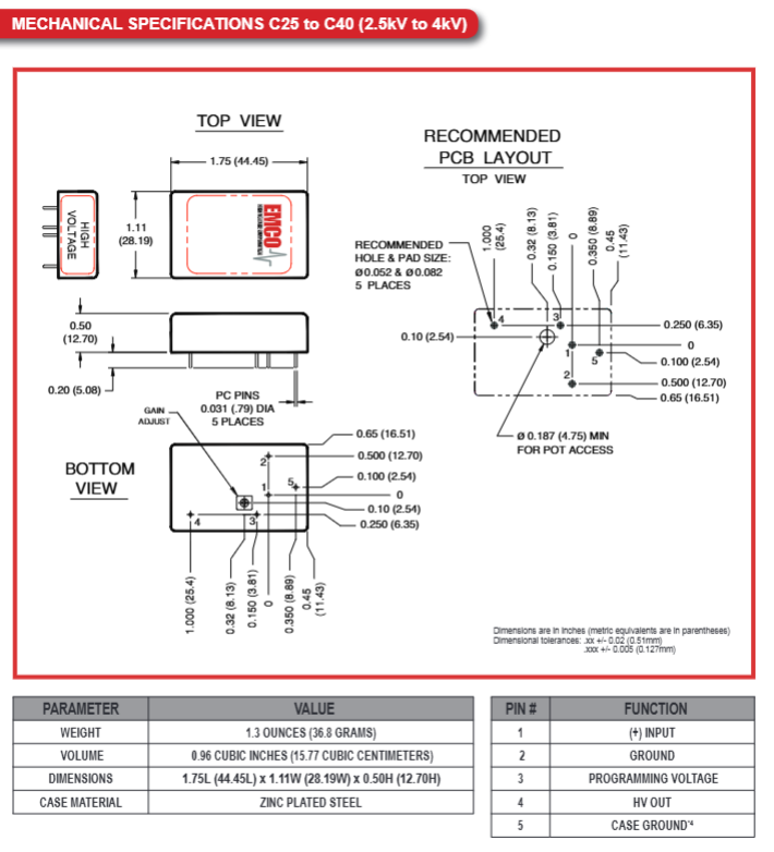
Medium high voltage (2.5kV-4kV) C25-C40 1.75 × 1.11 × 0.50 inches (44.45 × 28.19 × 12.70mm) 36.8 grams (1.3 ounces) 0.96 cubic inches (15.77 cubic centimeters)
High voltage (5kV-8kV) C50-C80 2.10 × 1.11 × 0.50 inches (53.34 × 28.19 × 12.70mm) 50.9 grams (1.8 ounces) 1.16 cubic inches (18.93 cubic centimeters)
(2) Installation and Accessories
Pin definition (5 pins in total): 1 pin (+input), 2 pins (ground), 3 pins (programming voltage), 4 pins (high voltage output/return), 5 pins (shell ground)
Standard installation: PCB installation, recommended aperture 0.052 inches, solder pad 0.082 inches
Optional accessories:
Flywire (FL suffix): Suitable for C01-C15 models, convenient for non PCB installation scenarios
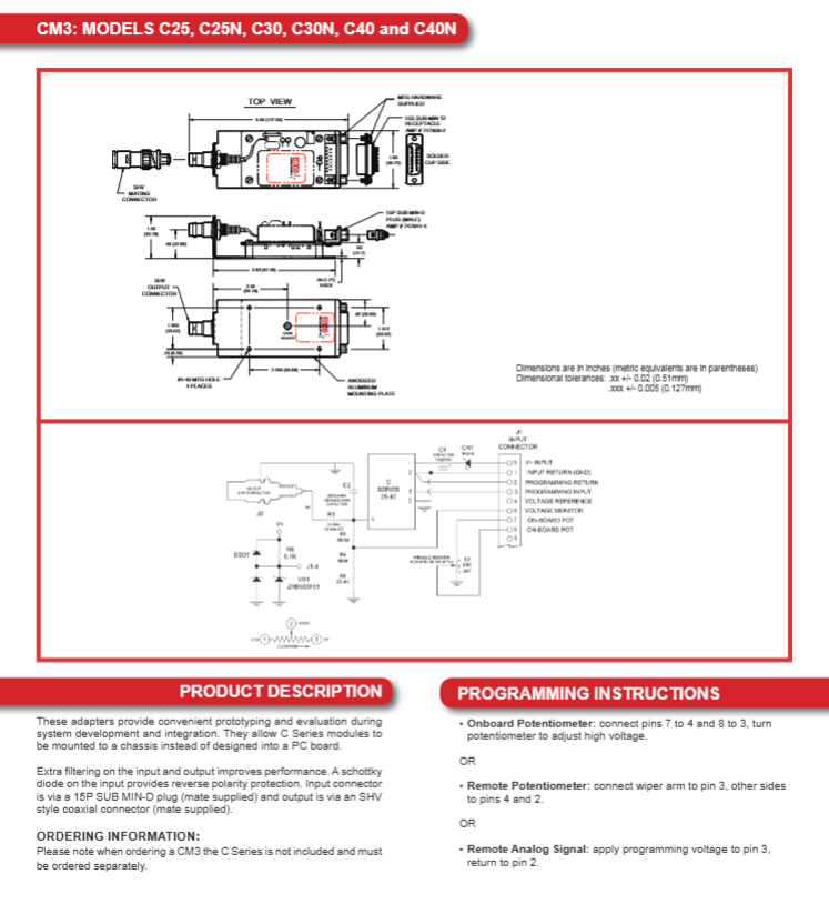
CM3 adapter kit: compatible with C25-C40 models, supports chassis installation, includes SHV output connector, reverse polarity protection
CM4 adapter kit: compatible with C50-C80 models, supports chassis installation, includes LGH output connector, additional filtering
Environment and reliability
Working temperature: -10 ° C to+60 ° C (shell temperature), thermal management is required
Storage temperature: -20 ° C to+90 ° C
Anti interference: using quasi sine wave oscillator, shielded transformer and excellent filtering technology, with extremely low EMI/RFI
Protection: Sealed design, resistant to immersion cleaning process
Mean Time Between Failures (MTBF):>26000 hours (Bellcore TR-332 standard, C10 model)
Order Information
Model naming convention: C+output voltage code+polarity (blank is positive, N is negative)+flying wire (blank is standard, FL is flying wire)
Example: C10N (1kV negative voltage standard version), C05FL (500V positive voltage flying wire version)
Attention: The CM series adapter kit does not include C-series modules and needs to be ordered separately