ProSoft AN-X-AB-DHRIO is a gateway for EtherNet/IP to Allen Bradley DH+or remote I/O, mainly used to solve common problems encountered when Allen Bradley PLC5 and SLC processors are connected to Data Highway Plus (DH+) or remote I/O networks. This gateway supports two configuration modes: as a DH+bridge, it allows HMI and RSLogix 5/500 software to connect and communicate with the processor, and also enables communication between the CompactLogix controller and PLC5/SLC on the DH+network; As a remote I/O scanner, PAC can control traditional remote I/O systems, assist in processor upgrades, support phased replacement of old I/O modules, and reduce downtime risks during upgrades.
Core functional features
(1) DH+Bridge Function
Network access: Allow HMI, programming terminals, and/or processors on EtherNet/IP networks to access traditional processors on DH+networks.
Configuration method: Configure through a web browser without the need for special configuration software.
Address and rate: DH+station address can be configured within the range of 0-77 (octal), supporting all DH+baud rates (57.6, 115.2, and 230.4 Kbaud).
Diagnosis and Status: Provides DH+network diagnosis function, which can view a list of all active nodes through a web browser; Multi color LED displays DH+network status.
(2) Remote I/O scanner function
Automatic configuration: The automatic configuration utility can detect baud rates and map racks, reducing configuration errors; Supports partial racks, with automatic configuration files that can be edited or customized after initial creation.
Speed and Connection: Supports all remote I/O baud rates (57.6, 115.2, and 230.4 Kbaud); Support offline configuration through CSV files.
Monitoring and diagnosis: Provide monitoring tools through a web interface to monitor input and output values; The webpage contains diagnostic information for block transfer, configured racks, and remote I/O networks.
Scale and Parameters: Supports up to 32 remote I/O adapters and rack numbers from 0 to 76 (octal); Supports 15 I/O connections with ControlLogix processors, and the RPI (Request Packet Interval) for each connection can be individually set within 5-750 milliseconds.
Tag Mapping: The automatic configuration function maps discovered remote I/O points to ControlLogix I/O connections, and users can specify alias base tags to map predefined I/O; Multi colored LED indicates the status of remote I/O network connection.
Hardware specifications
Port:
1 RJ45 10/100 Mbps Ethernet port
1 Phoenix 3-pin power connector
1 Phoenix 3-pin DH+or remote I/O connector
Typical power consumption: 300 mA at 12 Vdc or 150 mA at 24 Vdc
Maximum power consumption: 3.6W
Working temperature: 32 ° F to 122 ° F (0 ° C to 50 ° C)
Storage temperature: -40 ° F to 185 ° F (-40 ° C to 85 ° C)
Dimensions: 107 mm x 126 mm x 34 mm (4.18 inches x 4.97 inches x 1.33 inches, excluding connectors)
Humidity: 5% to 95% relative humidity, no condensation
Installation method: desktop use or DIN rail installation
Transfer rate
1、 EtherNet/IP network port
Speed: 10/100 Mbps adaptive, supports the standard transmission rate of Ethernet, and can automatically negotiate the optimal speed based on the connected device.
2、 DH+Network
Supports baud rates of 57.6 Kbaud, 115.2 Kbaud, and 230.4 Kbaud, which can be configured through the gateway to adapt to different speed requirements of DH+networks.
3、 Remote I/O network
Supporting baud rates: 57.6 Kbaud, 115.2 Kbaud, and 230.4 Kbaud. The gateway can automatically detect the baud rate of the remote I/O network and complete the configuration.
4、 Key Explanation
The data conversion between the Ethernet port of the gateway and the DH+/remote I/O port is achieved through internal processing, and the transmission efficiency is affected by network load and configuration parameters (such as RPI interval).
In remote I/O scanner mode, the RPI (Request Packet Interval) for each ControlLogix I/O connection can be set to 5-750 milliseconds, indirectly affecting the data refresh rate.
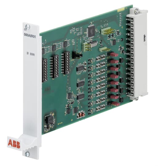
ABB 81EU01-E/R3210 is a 5-channel analog signal input module suitable for PROCOLOR systems, capable of processing 0/4-20mA signals and replacing various models of modules in the 81EA01 series. It adopts a compact design and supports multiple transmitter types, including 2-wire system (4-20mA, module power supply), 4-wire system (0/4-20mA, module power supply or external power supply), and can flexibly set parameters through a configuration list. Data is stored in EEPROM to prevent power loss.
Core functions
Signal processing and conversion: The current signal is converted into voltage through a high-precision measurement resistor of 50 Ω. It is then digitized by a multiplexer, instrument amplifier, and 12 bit A/D converter, supporting 12 bit precision output with quantization error<0.02% and linearity error<0.1%.
Correction and filtering calculation: Built in functional blocks such as KOR1 (water/steam flow correction), KOR3 (variable pressure gas flow correction), NIV (liquid level correction), FIL (nonlinear filtering), etc. Each functional unit can be equipped with one functional block, and the correction value is sent via telegram. The uncorrected original value can also be output.
Limit signal and event generation: Each functional unit can set up to 4 limit values, with four lag values available: HY1 (0.39%), HY2 (1.56% default), HY3 (3.12%), and HY4 (6.25%). If the limit is exceeded, it will be immediately notified by telegram. In event mode, data is transmitted when the limit response, monitoring trigger, or simulated value change exceeds the threshold (0.2% -6.8%, default 1.56%) and the time exceeds the set (40/200ms, default 200ms).
Simulation and diagnostic function: It can simulate up to 32 signals (including sending/receiving registers), with self diagnostic function. It displays faults through ST lights, diagnostic registers (246), and CDS system, such as process channel faults (unreasonable signals, reference value interference, etc.), and handles faults (invalid configurations, abnormal voltage, etc.).
Technical parameters
Electrical parameters
Power supply: UD is 4.9-5.1V (typical 5V, power consumption 220mA), US is 19.5-30V (typical 24V, power consumption varies with configuration, 2-wire transmitter with 140mA+7mA+measurement current per channel).
Input range: nominal 0-20mA/4-20mA, maximum -1-30mA, measured resistance 50 Ω, line resistance ≤ 100 Ω, line length ≤ 1000m.
Accuracy:<0.3% at 0-70 ℃,<0.1% at 23 ℃ delivery, temperature sensitivity<50ppm/K (typical 30ppm/K).
Physical parameters
Size: 6 units, 160mm deep, compliant with DIN 41612 interface, weight approximately 0.6kg.
Protection and anti-interference: electrostatic discharge immunity 8kV/4kV, RF field 10V/m, electrical fast transient 2kV, surge 2kV/1kV, conducted interference 10V.
Application and Configuration
Application scenario: Suitable for the acquisition and processing of analog signals such as flow and liquid level in industrial automation systems, supporting PROCONTOL station bus communication, and can be integrated with PLC and other systems.
Configuration method: Load the configuration list through PDDS, including transmitter type, measurement range, limits, function block type (1-5, KOR1/KOR3/NIV/FIL), filtering frequency (16 2/3/50/60Hz, default 50Hz), etc. After configuration, the ST light will turn off and the module will participate in bus communication.
Connection and Mechanical Design
Interface: X11 is a 48 pin station bus interface, X21 is a 32 pin process interface, supporting 2-wire/4-wire (module power supply/external power supply) connections. Please note that the reference potential difference should be ≤ 0.5V, and parallel USn output is not allowed.
Mechanical specifications: Board size 6 units, 160mm deep, connectors comply with DIN 41612, weight approximately 0.6kg.
The ABB TK457V050 industrial temperature controller is a high-precision temperature control device designed specifically for industrial environments. It is like a “temperature manager” in the industrial production process, relying on excellent performance to ensure stable operation of various industrial equipment under suitable temperature conditions, playing a key role in ensuring product quality and improving production efficiency. The controller has a compact appearance design, and the shell is made of sturdy and durable materials, which can effectively resist mechanical impact, dust, and moisture erosion in industrial environments, ensuring the safety of internal electronic components and extending the product’s service life. In terms of interface design, it is equipped with rich and practical interfaces, including analog input/output interfaces, digital communication interfaces, etc., which facilitate fast and stable connection and data exchange with various sensors, actuators, and upper control systems, and easily integrate into complex industrial automation control system architectures.
Specification parameters
Electrical parameters
Working voltage: It can adapt to AC power ranging from 100-240V, and this wide voltage adaptation range enables it to work normally in standard mains environments in most parts of the world. Whether in industrial power areas with frequent voltage fluctuations or relatively stable commercial power scenarios, it can ensure stable operation and provide reliable power supply guarantee for the controlled industrial equipment.
Temperature measurement range: It can accurately measure the temperature range of -50 ℃ to+250 ℃, meeting the monitoring needs of different temperature ranges in various industrial production processes. For example, in the freezing process of the food processing industry, precise monitoring of low-temperature environments can be achieved; In high-temperature operation scenarios such as metal smelting, accurate high-temperature data can also be obtained, providing reliable basis for temperature control.
Control accuracy: It has extremely high temperature control accuracy, up to ± 0.1 ℃. Such high precision can ensure that the temperature of industrial equipment is always maintained near the set value, effectively reducing the impact of temperature fluctuations on product quality. It is of great significance for production processes with strict temperature requirements, such as electronic chip manufacturing, high-end pharmaceuticals, and other industries.
Physical parameters
Size specifications: The overall size has been carefully designed, for example, it may be 120mm long, 80mm wide, and 60mm high (specific dimensions depend on the actual product). This compact design allows it to be flexibly adapted to installation positions such as control cabinets and equipment interiors with limited space, without occupying too much valuable space resources, making it convenient for industrial users to layout and install equipment.
Protection level: The protection level reaches IP54, which means it can effectively prevent dust and water splashes. In dusty industrial workshops or production environments where there may be a risk of water splashing, it can operate reliably, avoid internal circuit short circuits or damage caused by dust or water intrusion, ensure the normal operation of equipment, and reduce equipment failure rates.
Core functions
Accurate temperature control: Based on preset temperature values and real-time feedback signals from temperature sensors, advanced control algorithms are used to precisely regulate heating or cooling equipment. For example, in the plastic injection molding process, the mold temperature can be precisely controlled to shape the plastic at the optimal temperature, improving the dimensional accuracy and surface quality of plastic products; In the process of chemical reactions, ensure that the temperature inside the reaction vessel is stable within the precise range required for the reaction, ensuring the smooth progress of the chemical reaction and the stability of product quality.
Alarm and fault diagnosis: Equipped with comprehensive alarm functions, when the temperature exceeds the preset safe range or equipment malfunctions, it can immediately emit sound and light alarm signals to remind operators to take timely measures. At the same time, it is equipped with an advanced fault diagnosis system that can monitor and analyze the real-time operation status of itself and connected devices, quickly locate the fault point, and output detailed fault information through the display screen or communication interface, providing powerful troubleshooting basis for equipment maintenance personnel, shortening equipment downtime, and reducing production losses.
Data recording and communication: It can record temperature data in real time, and the storage capacity can be expanded according to user needs, making it convenient for users to query historical temperature curves, analyze temperature change trends during the production process, and provide data support for production process optimization. Supports multiple communication protocols, such as Modbus, Profibus, etc., and can seamlessly connect with control systems such as upper computers and PLCs to achieve remote monitoring and control. It facilitates centralized management and remote operation of temperature in the production site by operators in the central control room, improving the convenience and intelligence level of production management.
Precautions
Installation environment: It should be installed in a dry, ventilated, and non corrosive gas environment, avoiding direct sunlight and high temperature environments. The installation location should be far away from strong electromagnetic interference sources, such as large motors, transformers, etc., to prevent electromagnetic interference from affecting the normal operation of the controller. At the same time, it is necessary to ensure that the installation location has good seismic performance to avoid internal components becoming loose or damaged due to vibration.
Wiring operation: When performing wiring operations, be sure to cut off the power first to ensure safe operation. Strictly follow the wiring diagram in the product manual to ensure secure and correct wiring, and avoid problems such as short circuits and open circuits. Special attention should be paid to the polarity of the wiring between the temperature sensor and actuator to ensure proper connection, otherwise it may result in inaccurate measurements or equipment malfunction. After the wiring is completed, carefully check whether the wiring is correct and error free. Only after confirming that there are no errors can the power be turned on for testing.
Parameter setting and maintenance: Before use, it is necessary to set the various parameters of the temperature controller reasonably according to the actual application scenario and equipment requirements, such as temperature setting value, control accuracy, alarm threshold, etc. Regularly inspect and maintain the controller, including cleaning the casing, checking for loose wiring, and checking the measurement accuracy of the temperature sensor. At the same time, pay attention to the software upgrade information officially released by ABB, and promptly upgrade the software of the controller to obtain the latest functions and performance optimizations.
Fault handling: If the controller malfunctions, the fault type should be preliminarily determined based on the alarm information and fault indicator light. When troubleshooting, follow the principle of easy first and then difficult, check whether the power connection and wiring are loose, whether the temperature sensor is damaged, and whether the actuator is working properly. If the fault cannot be resolved by oneself, ABB professional technical support personnel should be contacted in a timely manner to avoid blindly disassembling the controller and causing the fault to expand. After troubleshooting, the controller should be thoroughly tested to ensure that it returns to normal working condition before being put into use.
The ABB DSRF197K01 control module is a key equipment designed specifically for complex scenarios such as industrial automation. It is like the “smart brain” of the system, responsible for accurately regulating the operation of various devices, ensuring the efficiency and stability of the entire production process. This module is designed to be extremely compact, with carefully considered dimensions that save installation space while not affecting its powerful functionality, making it easy to integrate into various industrial equipment and system architectures. The module is equipped with rich and efficient interfaces, which can quickly and stably exchange data and collaborate with peripheral devices, greatly improving the overall response speed and operational efficiency of the system.
Brand background
ABB, as an industry giant in the field of electrical and automation, has a profound history of over 140 years. With an unwavering pursuit of technological innovation and strict control over quality, ABB has deployed a wide business network worldwide, with approximately 105000 employees working together to deeply integrate advanced engineering experience with cutting-edge software technology, providing comprehensive and excellent solutions for many fields such as manufacturing, transportation, energy, and operations. In China, ABB has actively laid out a complete business system integrating research and development, manufacturing, sales, and engineering services. 27 local enterprises and 15000 employees are distributed in more than 130 cities, with online and offline channels covering about 700 cities, bringing internationally leading electrical equipment and technical support to the Chinese market.
Specification parameters
Electrical parameters
Working voltage: It can adapt to AC power ranging from 100-240V, and this wide voltage range allows it to operate stably in standard mains environments in most parts of the world. Whether in industrial power environments with large voltage fluctuations or relatively stable commercial power scenarios, it can ensure its normal operation and guarantee stable power supply for the controlled equipment.
Signal processing capability: With strong signal processing capabilities, it can quickly and accurately process various analog and digital signals. Its signal processing speed can reach hundreds of thousands of times per second or even higher, and it can respond to input signals in a very short time, adjust output control signals in a timely manner, and meet the high requirements for real-time and accuracy in industrial automation production.
Physical parameters
Size specifications: The overall size is compact, with optimized design for length, width, and height, such as 100mm in length, 60mm in width, and 40mm in height (specific dimensions depend on the actual product). This compact design allows it to easily adapt to installation positions such as control cabinets and equipment with limited space, without occupying too much valuable space.
Material and process: The shell is made of high-strength, fireproof, and corrosion-resistant engineering plastic material, which not only effectively resists external mechanical impact, dust, and moisture erosion, but also has good fire resistance performance, reducing potential fire risks. The internal circuit board adopts high-quality electronic components and advanced surface mount technology to ensure the stability and reliability of electrical connections and extend the service life of the module.
Core functions
Equipment control: It can accurately control various connected industrial equipment such as motors, valves, sensors, etc. based on preset programs and received external signals. It can achieve various operations such as starting, stopping, speed adjustment, and position control of the equipment. Through precise control instructions, it ensures stable operation of the equipment according to production process requirements, avoiding production deviations or equipment failures caused by improper control.
Data Collection and Analysis: With powerful data collection capabilities, it can obtain real-time operational data of connected devices, such as temperature, pressure, speed, current, etc. At the same time, it is equipped with advanced data processing algorithms that can analyze the collected data in real time and determine whether the device’s operating status is normal. Once abnormal data is detected, timely warning signals can be issued to provide strong basis for preventive maintenance of equipment and reduce production losses caused by sudden equipment failures.
Working principle
After the system is started, the DSRF197K01 control module first performs self initialization to check its hardware status and software program integrity. After initialization, the module continuously collects various signals from external devices such as sensors and operation panels through input interfaces. These signals are preprocessed by the signal conditioning circuit inside the module, such as filtering and amplification, and then transmitted to the central processing unit (CPU). The CPU analyzes and processes input signals based on built-in control algorithms and preset program logic, generating corresponding control instructions. These instructions are then sent to the corresponding executing devices, such as motor drivers, relays, etc., through output interfaces to achieve precise control of the devices. Throughout the process, the module continuously collects feedback signals from the device, compares the actual operating status with the preset target, and adjusts control instructions in a timely manner if there is a deviation to ensure the stability and accuracy of the device operation.
Key advantages
High reliability: Using high-quality electronic components and advanced manufacturing processes, and undergoing strict quality inspection processes, it can operate stably in harsh industrial environments such as high temperature, high humidity, and strong electromagnetic interference. Its mean time between failures (MTBF) is tens of thousands of hours, greatly reducing equipment maintenance costs and production interruption risks caused by module failures.
Excellent compatibility: The design fully considers compatibility with various industrial equipment and systems, supporting multiple communication protocols such as Modbus, Profibus, EtherNet/IP, etc. It can easily connect and exchange data with devices of different brands and models, making it convenient for users to build complex industrial automation control systems.
Flexible programming and configuration: Provides powerful and easy-to-use programming software and configuration tools, allowing users to flexibly program and configure modules through graphical interfaces or programming code according to actual production needs. Both simple logic control and complex process control can be quickly and conveniently implemented to meet the diverse needs of different users.
Precautions
Installation environment: It should be installed in a dry, ventilated, and non corrosive gas environment, avoiding direct sunlight and high temperature environments. The installation location should be far away from strong electromagnetic interference sources, such as large motors, transformers, etc., to prevent electromagnetic interference from affecting the normal operation of the module. At the same time, it is necessary to ensure that the installation location has good seismic performance to avoid loosening or damage to internal components of the module due to vibration.
Wiring operation: When performing wiring operations, be sure to cut off the power first to ensure safe operation. Strictly follow the wiring diagram in the product manual to ensure secure and correct wiring, and avoid problems such as short circuits and open circuits. After the wiring is completed, carefully check whether the wiring is correct and error free. Only after confirming that there are no errors can the power be turned on for testing.
Software Upgrade and Maintenance: Regularly follow ABB’s official software upgrade information and upgrade module software in a timely manner to obtain the latest features and performance optimizations. During the upgrade process, it is necessary to strictly follow the upgrade guide to avoid software upgrade failure or module damage caused by improper operation. At the same time, regularly inspect and clean the hardware of the module, remove dust and debris from the surface, and ensure good heat dissipation of the module.
Troubleshooting: If a module malfunctions, the fault type should be initially determined based on the fault indicator light or error message. When troubleshooting, follow the principle of easy first and then difficult, check whether the power connection, wiring is loose, and external equipment is normal. If the fault cannot be resolved by oneself, ABB professional technical support personnel should be contacted in a timely manner to avoid blindly disassembling the module and causing the fault to expand.
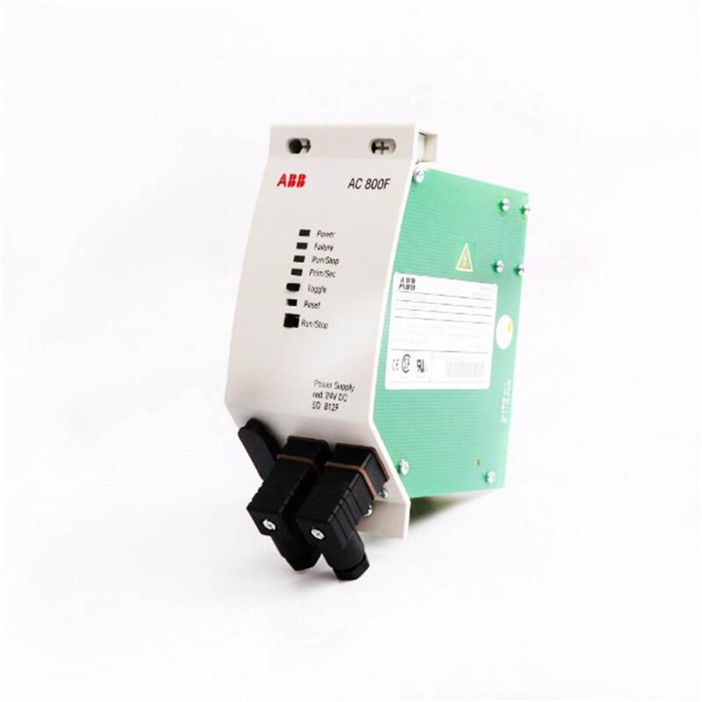
The power lines of ABB TK802F and SD802F/SD812F equipment, as key accessories for supplying power to corresponding equipment, shoulder the responsibility of stable transmission of electrical energy. Its design aims to meet the stringent power supply requirements of ABB’s professional equipment, ensuring that the equipment can operate continuously and efficiently in various environments. From the appearance, it has an ergonomically designed plug that is easy to plug and unplug; The cable part has good flexibility, which ensures normal power supply function while facilitating users to route according to actual scenarios.
Brand background
ABB is a technology leader in the field of electrical and automation, with over 140 years of outstanding history. It integrates engineering experience and software technology into solutions, which are widely applied in multiple fields such as manufacturing, transportation, energy, and operations. ABB has approximately 105000 employees worldwide, dedicated to driving innovation and accelerating industrial transformation. In China, ABB has comprehensive business activities including research and development, manufacturing, sales, and engineering services. It has 27 local enterprises and 15000 employees spread across more than 130 cities, with online and offline channels covering approximately 700 cities nationwide. With profound technical accumulation and persistent pursuit of quality, ABB has established a high reputation in the field of electrical equipment, and its product quality and reliability are highly recognized.
Specification parameters
Electrical parameters
Rated voltage: commonly 100-240V AC, it can adapt to the standard mains voltage in most regions around the world. This allows the equipment to be connected to the local power grid normally by simply replacing the corresponding plug adapter when used in different countries and regions, greatly improving the versatility of the equipment.
Rated current: Depending on the equipment power, the current carrying capacity is around 2-10A. For example, for SD802F devices with lower power, their power cords may only need to carry 2-4A current; For the high-power TK802F equipment, its power cord needs to have the ability to carry 6-10A current to ensure stable operation of the equipment and avoid performance degradation or even malfunction due to insufficient current.
Physical parameters
Cable material: The conductor part is made of high-purity copper, which has good conductivity and can effectively reduce losses during power transmission, ensuring stable and efficient power supply for the equipment; The outer sheath of cables is often made of flame-retardant and wear-resistant PVC or rubber materials, which can prevent the cables from being worn or scratched during daily use. At the same time, it has a certain degree of flame-retardant ability when encountering dangerous situations such as open flames, reducing the risk of fire and ensuring safe use.
Cable length: Available in various standard lengths such as 1 meter, 1.5 meters, and 2 meters. In scenarios such as office desks where the device is close to the power outlet, a 1-meter-long power cord is sufficient to meet the requirements; In industrial workshops and other environments where the installation location of some devices is far from the socket, users can choose 1.5-meter-long or 2-meter-long power cords to flexibly adapt to different usage scenarios.
Core functions
Electricity transmission: The core function of power lines is to stably and efficiently transmit the electricity from the mains to the equipment, ensuring the normal operation of various components inside the equipment. Its good electrical performance can ensure smooth current flow, avoid damage to electronic components caused by current fluctuations, and provide solid guarantees for the stable operation of equipment.
Electrical isolation: While transmitting electrical energy, the power line also has electrical isolation function. It can effectively block the possible stray currents and electromagnetic interference between the equipment and the mains power, prevent external interference signals from entering the equipment through the power line and affecting the normal operation of the equipment, and also avoid the interference generated inside the equipment from feedback to the mains power network and affecting other electrical equipment.
Working principle
When the power cord plug is inserted into the mains socket, the electrical energy from the mains enters the conductors inside the power cord through the metal pins of the plug. Due to the use of copper material with good conductivity, electrical energy is transmitted in the form of electron flow in the conductor, flowing from one end of the plug to the device end. During cable transmission, the insulation material on the outer layer prevents electrical energy from leaking out, ensuring that electrical energy is only transmitted inside the conductor. After reaching the device end, the electrical energy enters the internal power management module of the device through its power interface. This module further converts and stabilizes the input electrical energy, and then distributes it to various components of the device to drive it to operate normally.
Precautions for use and maintenance
Correct connection: When connecting the power cord, be sure to turn off the device power first to ensure safe operation. Insert correctly according to the device interface identification and power cord interface shape to avoid poor contact, inability to start the device properly, or even damage to the device and power cord due to reverse or improper insertion.
Regular inspection: During use, regularly check whether the power cord is damaged, aged, or overheated. If the outer sheath of the cable is found to be damaged, the power cord should be replaced in a timely manner to prevent leakage and safety accidents; If the power cord generates abnormal heat during use, it may be due to excessive current or poor internal conductor contact. It is necessary to immediately stop using and investigate the cause.
Storage requirements: When the power cord is not in use, it should be neatly arranged to avoid entanglement and knotting, and to prevent damage to the internal conductor due to excessive bending. The storage environment should be kept dry and ventilated, and the power cord should be protected from direct sunlight, high temperatures, or corrosive substances.
Digital quantity: may support standard TTL or CMOS level signals, used to connect digital devices such as switches, sensors, relays, etc.
Analog: If analog input and output are supported, the possible input and output ranges include voltage signals, such as 0-10V, ± 10V, etc; Current signals, such as 4-20mA, 0-20mA, etc.
Number of channels: Common ABB I/O modules have 8 channels, 16 channels, etc. For example, digital input/output modules may have 8 or 16 digital inputs and 8 or 16 digital outputs; The analog input/output module may have 4 or 8 analog inputs and 4 or 8 analog outputs, but the specific number of channels for 3BHE0930R0101 is unknown.
Electrical characteristics
Power requirements: Typically powered by 24V DC, some modules may also support other voltage levels such as 12V, 48V, etc.
Isolation feature: It has electrical isolation function, such as isolation between channels and between input and output and power supply. The isolation voltage may range from several hundred volts to several thousand volts to enhance the stability and anti-interference ability of the system, prevent electrical interference and fault propagation between different circuits.
Communication Protocol: It may support multiple industrial communication protocols, such as Modbus RTU/TCP, Profibus DP, EtherNet/IP, PROFINET, etc., for communication and data exchange with different controllers, upper computers, or other devices, achieving system integration and remote monitoring.
Working environment conditions
Temperature range: The working temperature range of general industrial grade I/O modules is around -25 ℃ to+60 ℃ or -40 ℃ to+85 ℃ to adapt to different industrial environmental temperatures.
Humidity range: able to operate stably within a certain humidity range, such as 5% -95% without condensation.
Features and functions:
High reliability: Using high-quality materials and advanced manufacturing processes, it can work stably in harsh industrial environments, has strong anti-interference ability, ensures the accuracy and stability of data transmission, and reduces system failures and downtime.
Multiple signal types supported: It may support multiple types of input and output signals, such as digital signals (such as switch input and output), analog signals (such as voltage and current signal input and output), etc., to meet the signal interface requirements of different industrial equipment and systems.
Flexible configuration options: Allow users to flexibly configure according to specific application scenarios and control requirements, such as determining input and output points, signal ranges, communication protocols, and other parameters through software or hardware settings, making it easy to integrate into various automation control systems.
High speed data processing capability: able to quickly collect input signals and output the processed results to meet the high real-time requirements of industrial control processes, such as timely and accurate signal processing and transmission in some motion control, process control and other scenarios that require fast response.
Good compatibility and openness: Supports multiple standard communication protocols such as Profibus, Modbus, EtherNet/IP, etc., making it easy to integrate and exchange data with other brands of devices or systems, and helping to build complex industrial automation networks.
Working principle
Basic concepts and functional positioning
I/O module is the core component for signal interaction in industrial automation systems, used to connect controllers (such as PLC, DCS) with field devices (such as sensors, actuators), to achieve data acquisition and control instruction output. As a leading enterprise in the field of industrial automation, ABB’s I/O module design follows the principles of high reliability, compatibility, and real-time performance, and is widely used in scenarios such as power, manufacturing, and energy.
Core working principle: The entire process of signal processing
1. Input Process
Signal acquisition:
Receive signals from on-site devices such as pressure sensors, limit switches, and temperature transmitters, which are divided into digital quantities (switch status, such as ON/OFF) and analog quantities (continuously changing values, such as 4-20mA current, 0-10V voltage).
Digital input: Isolating external circuits through optocouplers to prevent interference, converting level signals (such as 24V DC) into logic signals (0/1) recognizable by the controller.
Analog input: Continuous analog signals (such as voltage and current) are converted into digital signals (such as 12 bit or 16 bit binary numbers) through an analog-to-digital converter (ADC), and filtered and linearized to reduce the impact of noise.
Signal isolation and protection:
Adopting electrical isolation technology (such as optocouplers and transformer isolation) to avoid the impact of on-site equipment failures on the controller, while suppressing electromagnetic interference (EMI) and common mode voltage interference. For example, the isolation voltage can usually reach 500V~2500V to ensure system safety.
2. Output Process
Signal conversion and amplification:
Receive digital control instructions sent by the controller and drive field devices (such as relays, solenoid valves, and frequency converters) through digital or analog output.
Digital output: Logic signals (0/1) are converted into electrical outputs (such as 24V DC driven relays) through switching elements such as transistors, relays, or thyristors. Some modules support high-power outputs (such as 2A/channel).
Analog output: Digital instructions are converted into analog signals (such as 4-20mA current) through a digital to analog converter (DAC) to drive actuators (such as regulating valves) for continuous control.
Load protection and driving capability:
Integrate overcurrent and overvoltage protection circuits to prevent load short circuits or overload damage to modules, while optimizing driving capabilities based on load types (resistive, inductive, capacitive), such as configuring freewheeling diodes to eliminate back electromotive force for inductive loads.
3. Communication and Data Interaction
Communication with the controller:
Establish real-time connection with the controller through industrial communication protocols such as Profibus, EtherNet/IP, Modbus, and periodically exchange input data (collected field signals) and output data (controller instructions). For example:
In EtherNet/IP networks, I/O modules act as slave stations, sending input data and receiving output update instructions as requested by the master station (controller).
Some modules support the “hot plug” function, allowing for module replacement during system operation, and the communication protocol will automatically handle device status changes.
Data caching and real-time guarantee:
Built in cache memory (such as FIFO) temporarily stores input/output data to ensure that data is not lost in case of communication interruption; Using hardware timers or dedicated chips to achieve high-speed data refresh (such as 1ms response), meeting real-time control requirements.
Key technical characteristics and working mechanism
1. Modular design and scalability
ABB I/O modules typically use backplane buses (such as ABB’s S800 I/O system) or distributed architectures (such as AC 800M controller I/O modules), flexibly expanding the number of channels through physical slots or network interfaces, and supporting mixed configurations (digital, analog, special function modules).
2. Diagnosis and Self Maintenance Mechanism
Status monitoring: Real time monitoring of module power, temperature, and channel faults (such as disconnection and short circuit), visually displaying the operating status through LED indicator lights (such as RUN, ERROR, channel status).
Fault handling: Some modules support the “fail safe” mode, which automatically sets the output to a safe state (such as disconnecting a relay) and sends an alarm message to the controller when an abnormality is detected.
3. Environmental adaptability design
For industrial environment optimization, it supports wide temperature range (such as -40 ℃~+70 ℃), anti vibration (such as complying with IEC 60068-2-6 standard), and moisture and dust prevention (such as IP20 protection level), ensuring stable operation under harsh working conditions.
Collecting position signals from sensors (photoelectric switches, proximity switches) through digital I/O modules to determine whether the workpiece is in place;
The analog I/O module monitors parameters such as motor current and temperature, and adjusts the operating speed in real-time;
The output channel drives actuators such as solenoid valves and cylinders to complete assembly actions, such as robotic arms grasping parts.
2. Process Control and Process Industry
Application scenarios: Temperature and pressure control of chemical reaction vessels, liquid level regulation of fermentation tanks in pharmaceutical factories, flow monitoring of petroleum refining equipment.
Technical features:
Analog I/O modules (such as 4-20mA current input/output) are connected to pressure transmitters and regulating valves to achieve PID closed-loop control;
I/O modules that support explosion-proof certification (such as ATEX, IECEx) are used in hazardous areas to prevent sparks from causing explosions.
In the field of electricity and energy
1. Substation automation system
Application scenarios: High voltage switchgear monitoring, relay protection device interface, transformer status monitoring.
Key functions:
Digital input collection of circuit breaker opening and closing status, relay protection signals;
Digital output control switch for opening and closing, in conjunction with SCADA system to achieve remote operation;
Supports IEC 61850 communication protocol and seamlessly integrates with power automation systems.
2. Renewable energy generation
Application scenarios: wind turbine pitch control, solar photovoltaic inverter monitoring, energy storage battery management system.
Technical requirements:
The high-speed I/O module processes high-frequency analog signals such as wind speed and torque, with a response time of milliseconds;
Anti electromagnetic interference design, suitable for strong electromagnetic environments such as frequency converters and transformers.
Architecture and Infrastructure
1. Intelligent Building Automation
Application scenarios: Central air conditioning system, elevator group control, security access control linkage.
Typical configuration:
Digital input connects to access control card swiping signal, triggering elevator floor permission control;
Analog output adjusts the opening of the air conditioning chilled water valve to maintain indoor temperature;
Supports BACnet and Modbus protocols, integrated with Building Management Systems (BMS).
2. Municipal engineering and environmental protection equipment
Application scenarios: Start stop control of sewage treatment plant water pumps, water quality monitoring of water plants, and pressure monitoring of urban pipeline networks.
Environmental adaptability:
Wide temperature design (-20 ℃~+60 ℃) suitable for outdoor working conditions;
Moisture proof and dust-proof structure (such as IP65 protection level), suitable for harsh environments such as sewage tanks.
Metallurgical and Heavy Industry
1. Steel rolling production line
Application scenarios: adjustment of roll gap in hot rolling mill, tension control in cold rolling mill, monitoring of material level in blast furnace.
Special requirements:
High power I/O module directly drives hydraulic servo valve (current up to several amperes);
Anti vibration design (such as through ISO 16750 vehicle vibration standard) to adapt to high-frequency vibration environments of rolling mills.
Product model: 3BHB004027R0101 GVC700AE01, this is a specific model designated by ABB for this thyristor module, used to accurately identify and distinguish this product from other similar products.
Country of Origin: Sweden. ABB, as a well-known multinational enterprise, has production bases in multiple regions around the world. This module is originally from Sweden.
Weight: 0.14kg, overall light weight, easy to handle and install during actual installation and use.
Size: 6.6cm × 6.2cm × 8cm. The compact size makes this module suitable for compact installation environments and easy integration into various devices and systems.
Functional Features
High voltage and high current processing capability: As a thyristor module, it can withstand high voltage and high current, and can be used to control and regulate the transmission and conversion of electrical energy in high-power power systems, ensuring the stable operation of the power system.
Fast switching characteristics: With fast switching response capability, it can achieve conduction and disconnection in a short time, accurately control the on/off of current, meet various complex power control requirements, and improve the efficiency and performance of the system.
High reliability: Adopting advanced manufacturing processes and high-quality materials, it has high reliability and stability, and can work stably for a long time in harsh industrial environments, reducing maintenance costs and downtime.
Complete protection function: It is usually equipped with multiple protection mechanisms, such as overvoltage protection, overcurrent protection, overheating protection, etc., which can effectively protect the module itself and other devices connected to it from overload, short circuit and other faults, improving the safety and reliability of the system.
Application area
Industrial automation: used in the industrial production process to control the operation of various motors, drivers, frequency converters and other equipment, achieve precise control and automation management of the production process, and improve production efficiency and product quality.
Power transmission and distribution: It can be applied in the field of power transmission and distribution, such as high-voltage direct current transmission (HVDC) systems and reactive power compensation devices (SVC), to control the direction, size, and stability of power transmission, ensuring the reliable operation and efficient power supply of the power system.
Renewable energy generation: In renewable energy generation systems such as solar photovoltaic and wind power, it is used to control the operation of inverters, convert direct current into alternating current, and achieve grid connection with the power grid, improving the utilization efficiency and power quality of renewable energy.
Motor control: used for the start, stop, speed regulation and other control of various motors. It can accurately control the operating status of motors according to different working conditions, achieve energy saving and consumption reduction, and optimize equipment operation.
Working principle
A thyristor is a semiconductor device with a four layer structure, consisting of alternating P-type and N-type semiconductors, forming three PN junctions. Under normal circumstances, the thyristor is in a cut-off state. When a suitable trigger signal is applied to its gate, the thyristor will quickly conduct, allowing current to pass through. When the current decreases to a certain degree or a reverse voltage is applied, the thyristor will automatically turn off, stopping the flow of current. By controlling the timing and pulse width of the gate trigger signal, the conduction time and degree of the thyristor can be accurately controlled, thereby achieving regulation and control of power parameters such as current and voltage.
Precautions for use
Installation requirements: When installing this module, strictly follow the requirements of the product manual to ensure the correct and secure installation position, and avoid mechanical vibration and impact. At the same time, attention should be paid to the heat dissipation of the module to ensure good heat dissipation and prevent module overheating and damage.
Electrical connection: Connect the electrical pins of the module correctly to ensure a secure and reliable connection, avoiding problems such as poor contact or short circuits. When connecting power lines and load lines, pay attention to the matching of polarity and voltage level to prevent reverse connection or overload.
Environmental conditions: This module should be used under specified environmental conditions, avoiding use in harsh environments such as high temperature, humidity, high dust, and corrosive gases. If the environmental conditions do not meet the requirements, it may affect the performance and lifespan of the module, and even lead to module damage.
Maintenance: Regularly inspect and maintain the module, clean the dust and dirt on the surface of the module, check for loose electrical connections, and inspect for any abnormal phenomena such as overheating, discoloration, and odor. If any problems are found, they should be dealt with or modules should be replaced in a timely manner to ensure the normal operation of the system.
Power processing capability: This IGCT module can handle up to 100kW of power, meeting the operational requirements of numerous industrial equipment and systems with high power demand, and providing stable and strong power support for various complex industrial scenarios.
Working voltage range: Its working voltage range is between 600V AC and 1200V AC, which enables it to adapt to diverse medium voltage power standards in different regions and industrial environments, and has wide applicability. It can operate reliably in both general industrial production workshops and precision manufacturing fields that require high voltage stability.
Switching frequency: The maximum switching frequency can reach 10kHz, enabling the module to quickly and accurately control current and voltage, ensuring efficient operation of the power system. In application scenarios that require frequent power switching and adjustment, the ability to quickly respond to control instructions ensures the dynamic performance of the system.
Insulation level: It has an insulation level of H (180 ° C), which means it can maintain good insulation performance in high temperature environments, effectively preventing electrical short circuits and other faults, and improving the reliability and safety of the module in complex working environments. Even in some industrial places with poor heat dissipation conditions or high ambient temperatures, it can still work stably.
Cooling method: Adopting air-cooled cooling method, this cooling method has a relatively simple structure and does not require a complex water-cooled circulation system, reducing equipment maintenance costs and system complexity. At the same time, the air cooling method can to some extent meet the heat dissipation needs of the module during normal operation, ensuring that the module operates within a suitable temperature range, thereby extending its service life.
Product Features
Excellent electrical performance: IGCT modules have strong electrical performance advantages. On the one hand, it can withstand high voltage and high current, maintain stable operation under high voltage and high current working conditions, and is not prone to device damage and other problems. On the other hand, it has a long service life, thanks to advanced semiconductor materials and manufacturing processes, which slow down the performance degradation of modules during long-term, high-intensity operation, greatly reducing the frequency of equipment replacement, lowering maintenance costs, and improving the continuity and stability of industrial production.
Advanced design concept: Utilizing IGCT technology, advanced materials and processes are employed in the design. The casing is usually made of sturdy aluminum material, which not only has good mechanical strength and can effectively protect the internal precision semiconductor components from external mechanical impacts, but also has certain heat dissipation performance, helping to improve the overall heat dissipation efficiency of the module. The internal semiconductor components have been carefully selected and optimized to ensure efficient and stable operation of the module under various working conditions, achieving a perfect combination of high performance and high reliability.
Wide environmental adaptability: With a wide working temperature range, it can adapt to various extreme temperature environments from cold Arctic regions to hot desert areas. At the same time, its high insulation resistance characteristics enable the module to maintain good electrical performance even in harsh environmental conditions such as humidity and dust, without causing electrical failures due to insulation performance degradation caused by environmental factors. This excellent environmental adaptability enables the IGCT module to be widely applied in various complex industrial environments worldwide.
Product specifications
Size: The module size is 165mm x 100mm, which is designed to be compact and reasonable, making it easy to install and integrate in the limited space of various industrial equipment. It can effectively save equipment space and improve the flexibility of equipment layout. Both small industrial control cabinets and large power equipment cabinets can conveniently accommodate this module.
Weight: The weight is about 0.3kg. The relatively light weight not only facilitates the installation and handling of the module, reduces the labor intensity during the installation process, but also helps to reduce the overall load of the equipment. It is of great significance for some application scenarios that have strict requirements for equipment weight, such as some special power equipment in the aerospace industry.
Certification: This product has passed internationally renowned certifications such as CE and UL. CE certification indicates compliance with European safety, health, and environmental standards, while UL certification reflects recognition of its safety and reliability in the US market. These certifications are a strong endorsement of product quality and performance, providing users with confidence in using the product globally, ensuring that the product complies with local regulations and standards in different countries and regions.
Application Fields
Industrial automation: In industrial automation production lines, this IGCT module is commonly used for motor control. For example, in the conveyor belt system of a large automated factory, precise control of the motor can achieve stable and efficient operation of the conveyor belt, ensuring fast and accurate transmission of products on the production line. In terms of motion control of automated mechanical equipment, it can accurately adjust parameters such as motor speed and torque according to production process requirements, ensuring the accuracy and stability of equipment motion, thereby improving product processing quality and production efficiency.
Power system: IGCT modules play an important role in high-voltage transmission and distribution in the power system. For example, in high-voltage direct current transmission (HVDC) systems, it is used to achieve AC-DC conversion, which can efficiently control the direction and power size of power transmission, and improve the stability and reliability of the transmission system. In medium voltage distribution networks, it can be used for equipment such as Static Var Compensators (SVC) to quickly and accurately compensate for the reactive power of the power grid, improve the power quality of the grid, reduce line losses, and ensure the safe and stable operation of the power system.
New energy generation: This module is also widely used in new energy fields such as wind power generation and solar photovoltaic power generation. In the wind power generation system, the inverter used for wind turbines is used to convert and control the output electrical energy of the generator, ensuring that the wind turbine can stably convert wind energy into electrical energy and connect it to the grid. In solar photovoltaic power generation systems, it can be used as a photovoltaic inverter to convert the direct current generated by photovoltaic panels into alternating current, achieving efficient matching with the power grid and stable output of electrical energy, improving the overall efficiency and reliability of new energy generation systems.
RELIANCE INSPECTOR VCIB-06 is an advanced industrial visual display designed specifically for complex visual tasks in industrial environments. Its research and development background relies on Reliance Electric’s deep technical foundation and rich practical experience accumulated in the field of industrial automation for a long time. The company has been committed to providing reliable and efficient automation solutions for industrial users, and VCIB-06 is an innovative achievement under this concept.
Basic information
Brand and Model: RELIANCE is a brand under Eaton and has a high reputation in the field of industrial automation. VCIB-06 is a specific model of its Vectrive series AC servo drive.
Appearance design: The drive adopts a gray metal frame with dimensions of 15 inches x 15 inches x 19 inches. The front and bottom have eye-catching Ryan company logo stripes, with “Reliance Electric” and “Vectrive” printed on light blue and dark black stripes.
Functional Features
Control function: It can accurately control the speed, position, and torque of the motor, suitable for various industrial applications that require high-precision motion control, such as CNC machine tools, robots, automated production lines, etc. By using sine pulse width modulation (PWM) waveform to regulate the operation of the motor, smooth and stable motion control can be achieved.
Protection function: It has multiple protection functions such as overcurrent, overvoltage, undervoltage, overheating, etc., which can effectively protect the driver and motor from damage caused by overload, short circuit and other faults, and improve the reliability and stability of the system. When overheating is detected in the motor or driver, it will automatically reduce power or stop running to prevent equipment damage.
Communication function: Supports multiple communication protocols, such as Modbus, CANopen, etc., making it easy to network and communicate with other devices, achieving centralized control and monitoring, facilitating integration into complex industrial automation systems, and achieving collaborative work between devices.
Design Features
Durable and sturdy casing: The casing is made of high-strength metal material, which has excellent impact and vibration resistance. It can maintain structural integrity under harsh conditions such as vibration and collision commonly seen in industrial production, effectively protecting internal precision electronic components and ensuring stable operation of the equipment. At the same time, the shell design conforms to ergonomic principles, making installation and operation convenient.
Optimized heat dissipation structure: Considering that prolonged continuous operation in industrial environments may cause equipment overheating issues, VCIB-06 is equipped with efficient heat dissipation modules. Through carefully designed heat dissipation ducts and large-area heat sinks, the heat generated by equipment operation can be quickly dissipated, maintaining the internal temperature within the suitable working range (0 to 50 ° C), avoiding performance degradation or failure caused by overheating, and ensuring long-term stable operation of the equipment.
Protection level compliance: The product meets the NEMA 4X/12 protection level standard and has excellent dust, water, and corrosion resistance capabilities. This enables it to be used normally in industrial environments with high dust, humidity, and the presence of corrosive substances, extending the service life of equipment, reducing maintenance costs, and improving the reliability of industrial production.
Technical Parameter
Display performance: Equipped with a high-resolution display screen, it can clearly present various detailed information in industrial visual inspection. The specific resolution parameters can be flexibly customized according to different application scenarios and customer needs, meeting diverse requirements from ordinary precision detection to high-precision visual recognition. At the same time, it has high brightness and high contrast, ensuring clear and visible images even in strong or complex industrial environments, providing accurate visual feedback for operators.
Processing capability: Equipped with high-performance processors, it has powerful data processing capabilities and can quickly process and analyze large amounts of image data collected by industrial vision systems. By combining advanced image processing algorithms, it is possible to achieve rapid recognition, measurement, and defect detection of target objects, meeting the strict requirements for real-time and accuracy in industrial production.
Interface configuration: Equipped with a variety of interfaces, including but not limited to Ethernet interface, USB interface, RS-232 interface, etc. These interfaces facilitate the connection and data transmission with industrial cameras, sensors, controllers, and other devices, achieving seamless integration of industrial vision systems and meeting the networking needs of different industrial automation production lines.
Function characteristics
Image enhancement and analysis function: Equipped with advanced image enhancement algorithms, it can optimize the captured images, improve their clarity and contrast, highlight the features of the target object, and facilitate clearer observation and analysis by operators. At the same time, it has powerful image analysis capabilities that can automatically recognize and measure parameters such as size, shape, and position of target objects, and perform quality inspection and judgment according to preset standards, providing accurate data support for industrial production.
User friendly interface: Designed with a simple and intuitive user interface, operators can easily complete various operations such as parameter settings, image viewing, detection result analysis, etc. by touching the screen. The interface layout is reasonable, with clear functional zoning, greatly reducing the learning cost and operational difficulty of operators, and improving work efficiency.
Data Storage and Transmission: Equipped with a large capacity data storage function, it can store image data and detection results in real time during industrial visual inspection processes, facilitating subsequent queries, traceability, and analysis. At the same time, it supports high-speed data transmission and can quickly upload detection data to industrial networks or cloud servers, achieving data sharing and remote monitoring, making it easy for enterprise management to timely understand production situations and make decisions.
Application scenarios
Quality inspection in industrial manufacturing: Used for quality inspection of components and products on production lines in industries such as automobile manufacturing, electronic equipment manufacturing, and mechanical processing. Through visual recognition technology, defects such as scratches, cracks, and dimensional deviations on the surface of products can be quickly detected to ensure that product quality meets standards, improve product qualification rates, and reduce defect rates.
Logistics and Warehouse Management: Used for identifying, sorting, and inventory management of goods in logistics warehouses. By using industrial vision systems to recognize barcodes, QR codes, or external features of goods, automated sorting and inventory counting can be achieved, improving logistics efficiency, reducing labor costs, and minimizing human errors.
Equipment monitoring in the energy industry: used for real-time monitoring of equipment operation status in energy industries such as oil, natural gas, and electricity. By using visual analysis technology, the appearance of the equipment can be checked for any abnormalities such as damage or leakage, and potential faults can be detected in a timely manner to ensure the safe and stable operation of energy production equipment and avoid production interruptions and safety accidents caused by equipment failures.
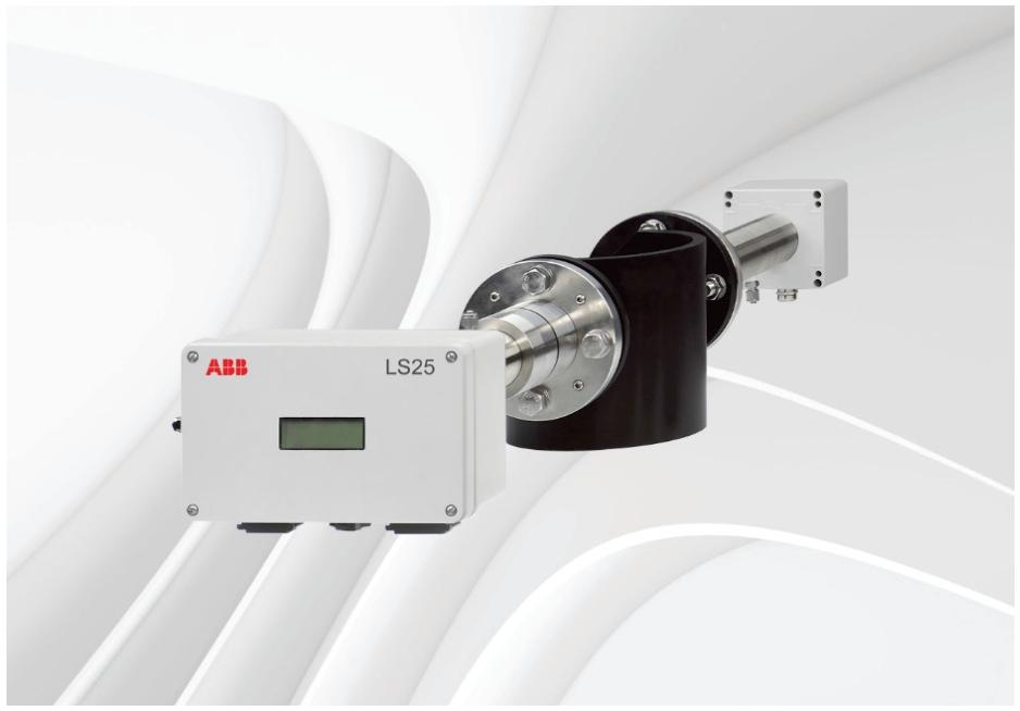
AO2000-LS25 is a laser analyzer launched by ABB, available in both universal and explosion-proof versions, designed to make measurement simple. It is based on the principle of Tunable Diode Laser Absorption Spectroscopy (TDLAS) and consists of three independent units: transmitter unit, receiver unit, and power supply unit. It can be used for continuous in-situ gas monitoring in chimneys, pipelines, process rooms, and other places.
Measurement principle
Using infrared single line absorption spectroscopy, each gas has a unique absorption line at a specific wavelength. By scanning the absorption line of the target gas and using wavelength modulation technology, the gas concentration is measured using second harmonic signals, and the measurement is only for free molecules of specific gases, without being affected by molecules that bind to other molecules or adhere to particles.
Instrument Description
Transmitter unit: including laser module, collimating optical components, and main electronic equipment, placed in a coated aluminum box.
Receiver unit: equipped with a focusing lens, photodetector, and receiving electronic device, also inside a coated aluminum box.
Power supply unit: converts 100-240V AC to 24V DC, which can directly supply power to the transmitter unit and connect 4-20mA input signals from external temperature/pressure sensors.
Protection and Performance: The protection level of the transmitter and receiver units is IP66, and the standard optical window can withstand an absolute pressure of up to 5 bar. The optical alignment is simple and reliable, and the blowing function can prevent dust and other pollutants from contaminating the optical window.
Software
User invisible programs integrated into CPU electronic devices, used to perform all necessary calculations and self-monitoring tasks.
A Windows based program that communicates with the instrument through an RS-232 connection for installation, service, and calibration, and does not require use during normal operation.
Laser classification and warning
When measuring oxygen, the laser is classified as Class 1M, and other sample components are classified as Class 1, in accordance with IEC 60825-1 standard. The laser emits invisible light.
Warning: 1M class laser products cannot be opened when powered on and cannot be viewed directly with optical instruments; Class 1 laser products cannot be opened when powered on.
Installation preparation
(1) Tools and other equipment
Two M16 bolt open-end wrenches, one 5mm hex wrench, one 2.5mm flathead screwdriver, and one 386 or higher configuration PC are required.
(2) Measurement point flow conditions
It is recommended to have at least 5 straight pipe sections with chimney diameters before the measurement point, and 2 straight pipe sections with chimney diameters after it.
(3) Monitor placement
The transmitter and receiver units should be easily accessible, and the receiver unit should have at least 1 meter of free space outward from the flange fixed on the chimney.
(4) Requirements for flanges and chimney holes
Two holes with a diameter of at least 50mm and diametrically opposite are required. The standard flange is DN50/PN10. The initial angle and alignment of the flange after welding must meet certain tolerance requirements. After adjustment, the maximum allowable angle drift between the laser beam and the central axis of the receiver unit caused by temperature or vibration is ± 0.3 °.
(5) Cable and electrical connections
The transmitter and receiver units are connected using the accompanying receiver cable, with a modified cable length not exceeding 20 meters.
The service PC cable is 3 meters long and can be extended to about 10 meters.
The maximum length of the power cable is 100 meters, the maximum length of the receiver cable is 150 meters, and the maximum length of the Ethernet cable is 100 meters or longer (depending on the local network configuration).
Installation
(1) Installation and adjustment
Install the alignment and blowing unit of the transmitter and receiver onto the flange according to the steps, perform blowing gas installation, window adapter ring installation, equipment body installation, cable connection and other operations.
Air blowing is used to keep the instrument window clean. The blowing gas should be dry and clean. It is recommended to use instrument air with a flow rate of about 20-50 liters/minute. Some applications require nitrogen blowing. The blowing flow rate of the transmitter and receiver units should be less than 0.5 liters/minute.
For applications involving toxic and highly corrosive gases, isolation flanges should be used, and process safety or thorough purging should be ensured before installation.
(2) Start up
When the electronic device is started, the LCD will display the startup mode information. The laser will only be turned on after the laser temperature stabilizes during the startup process, and the startup usually lasts less than 3 minutes.
After startup, it may display “laser alignment error” and “low transmission”, which are normal phenomena indicating that the transmitter and receiver units are not aligned.
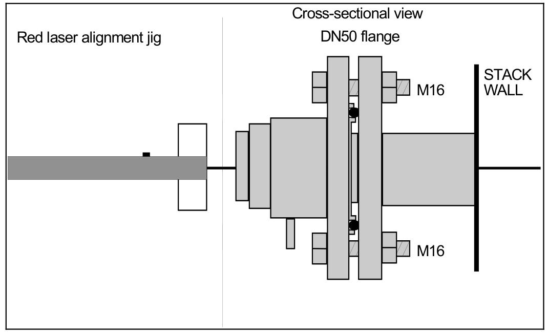
(3) Use a red laser to align the fixture with the transmitter/receiver
Alignment of transmitter unit: Remove the adapter ring, install the red laser alignment fixture, adjust to find the laser beam and move it to the center of the hole, and lock the alignment.
Receiver unit alignment: Similar to the transmitter unit alignment steps, reinstall the transmitter and receiver after completion, and check the transmission readings.
(4) Tune to achieve maximum transmission
Measure the alignment voltage with a voltmeter, adjust the adjustment screws on the transmitter and receiver sides to maximize the voltage reading, repeat until there is no further improvement, and tighten the locking screws.
(5) Connect PC
Copy the service software to the PC, connect the instrument via RS-232 or network, and set parameters such as process gas pressure, temperature, and concentration units.
Service Program
(1) Software startup
Select the connection method (serial port, modem, LAN, or demo mode), enter the IP address and port number, and start in user mode or advanced mode. The user mode interface is simplified, and the advanced mode requires a password.
(2) Measurement menu
Display parameters such as status, serial number, mode, concentration, line width, and transmission, which can be accessed through buttons to access different menus. The screen update cycle defaults to 5 seconds.
(3) Program menu
Draw Readings: Draw the measured average and instantaneous gas concentration, transmission, and spectral temperature (if applicable).
Second harmonic signal: displays the signal used to calculate gas concentration, which can be saved to a file for later analysis.
Record Reading: Record measurement data to an ASCII file with customizable sampling period, file name, and recording parameters.
View error logs: Download instrument error and warning logs, save or clear logs.
Measurement configuration: Set pressure and temperature input methods, optical path parameters, concentration averaging, instrument time, etc.
Gas specific parameters: select the measured gas, unit, output format, alarm level, etc.
Calibration instrument: There are two modes: proportional calibration and global calibration. Proportional calibration adjusts proportionally based on measurement and provided concentration, while global calibration also adjusts line width parameters, requiring stable reference gas conditions.
TCP/IP and modem configuration: Set IP address, subnet mask, port number, and gateway.
File download/upload: Download instrument readings and settings to PC, or upload settings from PC to instrument.
Manual instrument control: Force the instrument into sleep mode, reset the microcontroller, test the current circuit and digital I/O, etc.
(4) Configure through AO2000 central unit
The parameters of the laser analyzer can be configured through the AO2000 display and control unit, which has the same effect as using service software, including setting gas concentration units, temperature and pressure input methods and values, optical path parameters, etc.
Operation, maintenance, and calibration
(1) Operation mode
Startup mode: After booting up, perform initialization, self-test, and startup until the laser temperature stabilizes within an acceptable range.
Measurement modes: including normal, zero and span modes. Normal mode outputs measurement data periodically, while zero and span mode is used to verify instrument performance.
Fault mode: When the instrument detects a serious fault, it enters, stops measuring, and automatically attempts to restart after one hour.
(2) Maintenance
Daily maintenance: Regularly inspect optical transmission, clean windows and adjust alignment if necessary. For zero gas applications, test instrument response at least once every three months and check calibration every 3-12 months.
Clean the optical window: When the transmission drops below the reliable measurement level, clean it with non abrasive detergent or solvent. If there are cracks or damage, replace it.
Instrument alignment: When the alignment changes due to external stress, re align according to the installation procedure.
(3) Optimize flange blowing flow rate
There are two methods to determine the required purge flow rate: one is to turn off and turn on the purge flow, and analyze and measure concentration changes; Another approach is to adjust the measurement length and compare the concentration, and adjust the purge flow rate based on the results.
(4) Instrument calibration
The instrument has been calibrated with a certified gas mixture before leaving the factory, and does not require calibration after receiving it. After a period of use, it may need to be recalibrated due to laser aging. It is recommended to verify calibration annually with certified test gas and the provided gas pool.
Calibration requires the instrument to run for at least 1 hour, connect to the test cell, set the correct measurement configuration parameters, introduce calibration gas, stabilize, calibrate, and save the settings.
For reactive and “viscous” gases, stainless steel or PTFE tanks, shortest connecting pipes, and high flow blowouts should be used to ensure stable concentration.
(5) Troubleshooting
The LCD displays various fault messages, such as “low transmission”, “laser alignment error”, “PLC reading error”, etc. Based on the message explanation, corresponding measures are taken, such as cleaning the window, checking the connection, adjusting the alignment, etc. If the problem cannot be solved, download the error log and system log and contact the service personnel.
Electrical connection
(1) Transmitter unit interface
There are receiver connectors, main power connectors, service connectors, and network connectors, which are used to connect receiver cables, power and sensor inputs, service PCs, and Ethernet, respectively.
(2) Receiver cable connection
Detailed wiring of the receiver cable at both ends, including power supply, signal, temperature sensor, etc.
(3) Power cable connection
The wiring at both ends of the power cable includes temperature, pressure, flow probe input, and power input.
(4) RS-232 and Ethernet connectors
The functions of each terminal of the RS-232 connector and the wiring of the Ethernet RJ-45 connector.
(5) Ethernet connection to AO2000
According to the AO2000 software version, the method of connecting one or more laser analyzers is introduced, including IP address setting and network topology structure.
(6) Current circuit (4-20mA) input connection
The connection method of active and passive 4-20mA current loop input probes was demonstrated, and multiple instruments can be connected in series to the same probe.
(7) Power cable connection
The power cable is connected to the power supply unit, and the cable diameter should be within the range of 5-10mm. The power terminal can accommodate conductors with an area of less than 2.5mm ².
(8) Transmitter board – fuse and LED
The transmitter board has a main fuse and some LEDs to indicate the status of different power supply voltages. If the LEDs are abnormal, the fuse and power supply need to be checked.