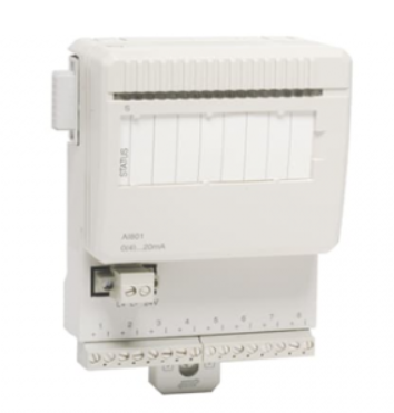
ABB 3BHE014135R0011 UAD149 A00-0-11 I/O module
Product Overview
The ABB 3BHE014135R0011 UAD149 A00-0-11 I/O module is a carefully designed modular I/O module mainly used in ABB’s AC 800PEC system, playing a crucial role in the field of industrial automation. This module cleverly integrates motion control and servo drive functions, providing strong support for diverse industrial automation application scenarios, and can effectively achieve data exchange and control instruction transmission between the system and external devices. Whether in complex industrial production lines or mechanical equipment with high automation requirements, it can ensure the stable and efficient operation of the entire system with its excellent performance.
Technical specifications
Electrical specifications:
Rated input voltage: 24VDC, able to adapt to common industrial DC power supply environments, ensuring reliable operation under stable power input.
Power consumption: The module has low power consumption, which effectively reduces energy consumption while running efficiently, meeting the energy-saving requirements of modern industry.
Physical specifications:
Weight: 1.29kg, moderate overall weight, easy to handle and operate during equipment installation and maintenance.
Size: 145mm × 145mm × 145mm, adopting a compact design with small space occupation, which is conducive to installation layout in control cabinets or equipment with limited space, and improves the flexibility of system integration.
I/O channel specifications: The specific number and type of I/O channels depend on the actual configuration, and multiple combinations can be provided to meet the diverse needs of different projects for input and output points and signal types. For example, it may include multiple analog input channels, analog output channels, digital input channels, and digital output channels, which users can flexibly configure according to actual application scenarios.
Core functions
Rich signal processing capabilities: This module can support a wide range of analog and digital I/O signals, making it easy to handle various complex industrial field signal types. Whether it is analog signals from sensors, such as continuously changing physical signals such as temperature, pressure, and flow rate, or digital signals representing device status, such as discrete signals such as switch on/off and device on/off, they can be accurately collected and processed, providing accurate data foundation for control systems.
High precision control and monitoring: With high precision and resolution, it can ensure accurate and error free control of equipment and monitoring of system operation status. For example, in the control process of key parameters such as motor speed and valve opening, extremely precise adjustment can be achieved to ensure the stability of the production process and the consistency of product quality. At the same time, when monitoring the operating status of the system, it can sensitively capture subtle changes and promptly detect potential problems.
Quick response mechanism: With fast scanning speed, it greatly reduces system latency. In industrial automation production, the production pace is usually fast and requires extremely high response speed from equipment. This module can quickly collect on-site signals and transmit processed control instructions to the executing mechanism, enabling the entire system to respond to various changes in a timely manner, effectively improving production efficiency and system real-time performance.
Built in diagnostic function: In order to facilitate troubleshooting and maintenance of the device, the module is equipped with comprehensive diagnostic functions. It can monitor its own operating status in real time. Once an abnormal situation is detected, such as hardware failure, communication interruption, signal abnormality, etc., it can immediately issue an alarm and provide detailed fault information to help maintenance personnel quickly locate the problem, shorten equipment downtime, and reduce maintenance costs.
Precautions
Installation environment requirements: It should be installed in a dry and well ventilated environment, avoiding humidity, high temperature, corrosive gases, and strong electromagnetic interference. The ambient temperature should be maintained within the operating temperature range specified by the module, generally between -10 ℃ and 50 ℃, to prevent the module’s performance and service life from being affected by excessively high or low temperatures. The installation location should be away from large motors, transformers, and other equipment that generate strong electromagnetic fields to ensure the normal operation of the module.
Wiring specifications: When performing wiring operations, it is necessary to strictly follow the requirements of the product manual. Ensure that the wiring is secure and avoid loose or loose connections to prevent unstable signal transmission or equipment failure. For the wiring of analog signals and digital signals, attention should be paid to distinguishing them, using cables of different colors, and taking shielding measures to prevent mutual interference between signals. At the same time, attention should be paid to the polarity of the wiring to avoid module damage caused by reverse connection.
Careful parameter setting: When setting parameters for modules, it is necessary to fully understand the actual requirements of the project and the operating characteristics of the equipment, and carefully set various parameters. Incorrect parameter settings may cause abnormal module operation and even affect the stability of the entire control system. After the setup is completed, comprehensive testing and verification should be conducted to ensure that all functions operate normally. During the operation of the system, if it is necessary to modify parameters, it should also be done while shutting down and making backups to prevent parameter loss or system failure.
Daily maintenance points: Regularly inspect the module to see if there are any signs of hardware damage, such as cracked casings or burnt components. Check if the wiring terminals are loose and tighten them in a timely manner. Keep the surface of the module clean to avoid the accumulation of dust, oil stains, and other factors that may affect heat dissipation and electrical performance. Regularly backup the system to prevent data loss. At the same time, attention should be paid to the running status of the module. If abnormal alarms or performance degradation are found, timely troubleshooting and handling should be carried out.
Similar model supplement
UAD148 series: Similar to 3BHE014135R0011 UAD149 A00-0-11, it is also used in ABB automation systems. The UAD148 series has basic I/O signal processing capabilities in terms of functionality, but may have slightly lower signal processing accuracy and scanning speed than the UAD149. For example, some models of UAD148 may have an analog signal measurement accuracy of 0.1%, while UAD149 can reach 0.05%; The scanning speed of UAD148 may be relatively slow, making it suitable for small industrial automation projects that do not require particularly high accuracy and response speed, and have limited budgets.
UAD150 series: This series of modules has certain similarities in functional characteristics with UAD149, both supporting multiple analog and digital signals. However, the UAD150 series may have more advantages in terms of the richness of communication interface types and communication protocol support. For example, UAD150 may have added support for a specific industrial communication protocol, suitable for industrial application scenarios that have special requirements for communication functions and require efficient data interaction with specific devices or systems. But in terms of price, the UAD150 series may be relatively high.