ABB 5SGY3545L0017 module tension controller
Product Overview
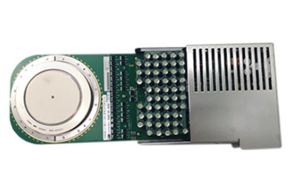
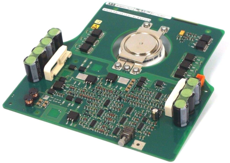
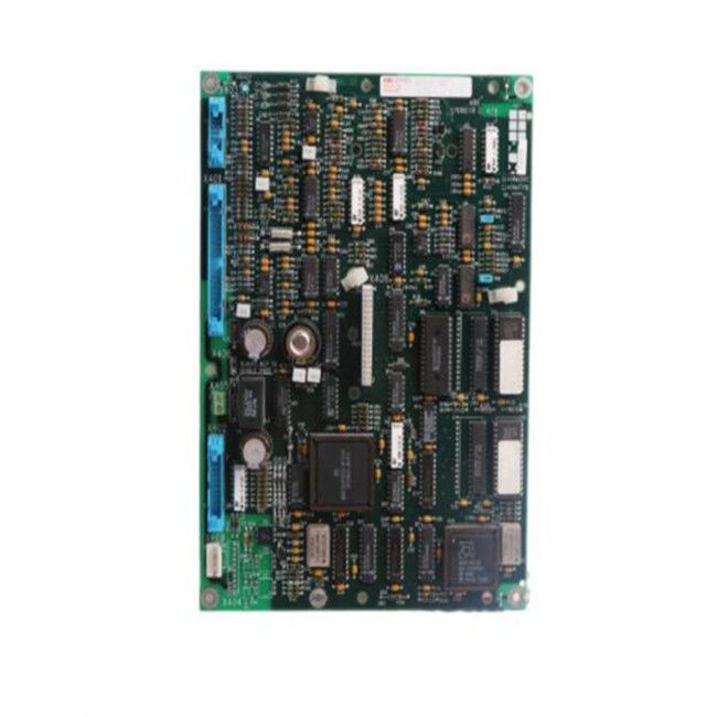
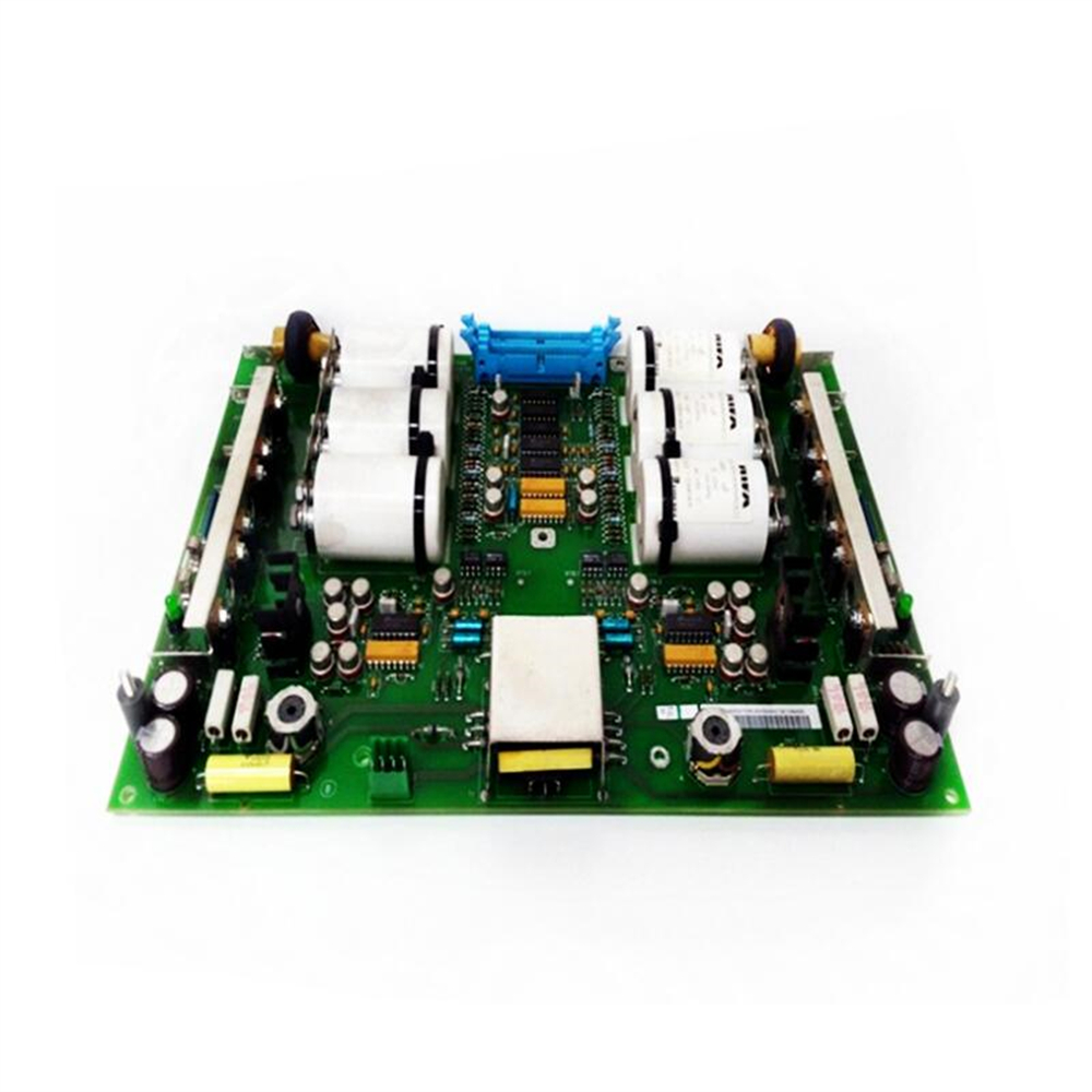
ABB SNAT602TAC Circuit Board is a circuit board that plays a key role in industrial automation and power control. It has a precise circuit layout and advanced electronic component integration, capable of efficiently processing various control signals and data transmission tasks, aiming to ensure the stable and accurate operation of industrial equipment and systems. It is an important basic component for building complex industrial control systems.
Specification parameters
Power specifications
Input voltage range: Suitable for 110-240V AC wide voltage input, can flexibly respond to power supply needs in different industrial environments, and reduce compatibility issues caused by voltage differences.
Frequency: Supports 50/60Hz standard frequency, meets common industrial power frequency requirements, and ensures stable operation.
Dimensions and physical characteristics
Dimensions: 200mm in length, 160mm in width, and 30mm in height. The compact size design facilitates installation in various control cabinets, equipment cases, and other space limited locations, effectively saving installation space.
Weight: Approximately 1.8kg. The moderate weight ensures the stability of the product structure while facilitating installation and handling, reducing the impact of vibration and other factors on circuit connections.
Interface type
Digital signal interface: equipped with multiple RS-485 interfaces, supporting half duplex communication mode, with a maximum transmission rate of 115.2kbps, it can achieve reliable connection with various digital devices such as sensors, actuators, controllers, etc., ensuring stable transmission of digital signals and collaborative work between devices.
Analog signal interface: It has a 4-20mA current loop input/output interface, which is used to connect analog sensors and actuators. It can accurately collect and output analog signals, and accurately adjust analog parameters such as temperature, pressure, and flow rate in industrial process control.
Working environment parameters
Temperature range: The working temperature ranges from -20 ℃ to+60 ℃, with excellent environmental adaptability. It can operate normally in harsh industrial environments such as high and low temperatures, reducing the impact of environmental temperature fluctuations on circuit board performance and ensuring production continuity.
Humidity range: Relative humidity of 5% -95% (without condensation), can work stably in humid environments, effectively preventing short circuits, corrosion and other faults caused by humidity issues, and improving product reliability.
Protection level: reaching IP20 protection level, it can effectively block solid foreign objects larger than 12mm from entering, providing basic protection for internal precision electronic components and reducing the risk of malfunction caused by foreign objects entering.
Core functions
Precise control signal processing: It can quickly analyze and process control instructions from the upper computer or other control sources, generate precise control signals, and output them to various connected industrial equipment such as motors, valves, etc., to achieve precise adjustment of equipment operating parameters (such as speed, opening, etc.), ensuring the accuracy and stability of the production process. In automated production lines, the movements of robotic arms can be precisely controlled to complete high-precision assembly tasks.
Efficient data collection and transmission: With powerful data collection capabilities, real-time device operation status data (such as temperature, pressure, position, etc.) is obtained through connected sensors, and the collected data is quickly processed and analyzed. At the same time, the processed data can be efficiently transmitted to the upper computer or other systems, providing data support for production decision-making and achieving information management and monitoring of the production process.
Communication protocol support: Supports multiple industrial communication protocols, such as Modbus RTU, Profibus DP, etc., which can seamlessly communicate with different manufacturers and types of devices, facilitating the construction of complex industrial automation systems, achieving high integration and collaborative work of the system, and meeting the diverse needs of industrial automation application scenarios.
Working principle
Instruction reception and parsing: Receive control instructions from upper level computers (such as PLCs, industrial control computers, etc.) through communication interfaces, which include key information such as equipment operation mode, target parameters, and action sequence. The microprocessor inside the circuit board decodes and parses the received instructions, converts them into executable control signals, and provides a basis for subsequent device control.
Data collection and processing: Various sensors connected to the circuit board collect real-time operational status data of the equipment, convert it into electrical signals, and transmit them to the circuit board. The analog-to-digital conversion circuit on the circuit board converts analog signals into digital signals. The microprocessor uses preset algorithms to analyze and calculate the collected data, determine whether the device is running normally, and compare it with preset standard parameters to determine the next control strategy.
Control signal output: Based on the data processing results, the microprocessor generates corresponding control signals, which are sent to connected actuators (such as motor drivers, solenoid valves, etc.) through output interfaces to drive actuator actions, achieve precise adjustment and control of equipment operating status, and ensure that the equipment operates according to predetermined requirements.
Feedback and adjustment: Continuously monitor the operating status of the equipment and receive feedback signals from the equipment. Compare the actual operation of the equipment with the expected target in real time. Once any deviation is found, adjust the control strategy and output signal immediately to form a closed-loop control system, continuously optimize the equipment operation performance, improve control accuracy and stability, and ensure the reliable production process.
Key advantages
High performance and stability: Adopting advanced manufacturing processes and high-quality electronic components, it has undergone strict quality inspection and aging testing, and has excellent anti-interference ability and stability. In complex electromagnetic environments, voltage fluctuations, and other harsh working conditions, it can still operate stably, ensuring precise and reliable equipment control, reducing the occurrence of failures and downtime, and improving production efficiency.
Flexible Scalability: Rich interface types and modular design enable it to have good scalability. Users can easily add functional modules and connect more devices according to their actual production needs, easily achieve system upgrades and expansions, and adapt to the constantly changing needs of industrial automation development.
Easy to maintain and diagnose faults: Equipped with comprehensive self diagnostic functions, it can monitor its own working status in real time. Once a fault is detected, an alarm signal is immediately issued and detailed fault information is recorded to help maintenance personnel quickly locate and troubleshoot the problem. The concise operation interface and intuitive parameter setting method reduce the difficulty of operation and maintenance personnel, and improve equipment maintenance efficiency.
Precautions
Installation environment requirements: It should be installed in a dry, well ventilated environment without severe vibration and electromagnetic interference. Avoid installation in damp, dusty, high-temperature, or corrosive gas environments to prevent affecting the performance and service life of circuit boards. The installation location should be away from strong electromagnetic interference sources such as large motors and transformers. If unavoidable, effective shielding and grounding measures should be taken.
Precautions for power connection: When connecting the power supply, it is necessary to strictly follow the product specifications and correctly connect the appropriate power supply voltage and phase sequence. Carefully check whether the power supply circuit is firm and reliable to prevent loosening, short circuits, and other situations from occurring. It is strictly prohibited to connect or disconnect the power supply while it is live, in order to avoid electric shock accidents or damage to the circuit board.
Key points of operation and maintenance: Operators need to undergo professional training and be familiar with the operation methods and parameter settings of circuit boards. When adjusting parameters, be cautious to avoid abnormal device operation caused by incorrect settings. Regularly clean and inspect the circuit board, remove surface dust and debris, check for loose interface connections, and inspect for signs of damage to components. If any abnormalities are found, the equipment should be shut down in a timely manner for handling, and it is strictly prohibited to operate the equipment with problems.
Software upgrade instructions: If a software upgrade is required, the original configuration data should be backed up first to prevent data loss during the upgrade process. Download officially recognized upgrade software and follow the correct upgrade steps. During the upgrade process, ensure stable power supply to the equipment to avoid upgrade failure and damage to the circuit board due to power outages or other reasons.
Similar model supplement
SNAT603TAC: Compared to SNAT602TAC, it has improved data processing capabilities by using a higher performance microprocessor, which increases data processing speed by about 30%. It is suitable for industrial scenarios that require extremely high data processing speed, such as real-time control in high-speed automated production lines.
SNAT601TAC: This model has relatively fewer interfaces and lower costs. For example, its RS-485 interface quantity is 2, which is less than the 4 of SNAT602TAC. It is suitable for small industrial control systems with relatively simple device connection requirements and limited budgets, such as single machine control of small automation equipment.