Call us 24/7uaedcs@163.com
Welcome to the official website of CNIACS Automation Technology Co., Ltd!
Call us 24/7uaedcs@163.com

ABB RET 541/543/545 Transformer Terminal Device

Product positioning and core features

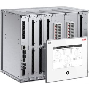
RET 541/543/545 is a protection, control, measurement, and monitoring device designed specifically for double winding transformers and generator transformer units in medium voltage distribution networks, suitable for harsh environments such as heavy industry, marine, and offshore. Its core advantages include:

Modular design: Supports 1/2 × 19 inch chassis, can expand functions through RTD/analog modules, and adapt to the needs of substations of different scales.

High performance protection: Integrated stable differential protection, high/low impedance grounding protection, and multi-stage overcurrent protection, response time<50ms, supporting CT saturation adaptive.

Multi protocol communication: Built in SPA, LON, IEC 60870-5-103, Modbus, DNP 3.0 protocols, can be connected to Profibus DP or IEC 61850 systems through adapters.

Core protection function

Differential and grounding protection

Three phase differential protection (87T): including second harmonic/fifth harmonic braking and waveform recognition locking, automatically matching transformer vector group, supporting zero sequence current elimination, preventing misoperation of faults outside the area.

High/Low Impedance Grounding Protection (REF): The high impedance principle does not require a stable resistor, while the low impedance principle supports CT variable ratio inconsistent scenarios, with a sensitivity of up to 5% of the rated current.

Overcurrent and backup protection

Multi stage overcurrent protection (51/50): supports definite time (DT) and inverse time (IDMT) characteristics, with three-stage low setting, two-stage high setting, and instantaneous period, with an action accuracy of ± 2.5%.

Directional overcurrent protection (67): Based on phase voltage/line voltage polarization, it supports forward/reverse action direction and has strong resistance to load intrusion.

Voltage and frequency protection

Overvoltage/undervoltage protection (59/27): three-stage phase voltage protection, residual voltage protection (59N) adapted to ground faults, action time<66ms.

Overexcitation protection (24): Based on U/f ratio monitoring, two-stage alarm/trip to prevent magnetic core saturation.

​Auxiliary protection

Thermal overload protection (49T): Dual time constant model, real-time monitoring of winding temperature, supporting RTD input (such as Pt100).

Circuit breaker failure protection (62BF): When detecting refusal to move, quickly trip adjacent circuit breakers with a response time of less than 20ms.

Measurement and monitoring functions

real-time

Support three-phase current/voltage, sequence component, power, frequency, and harmonic analysis (suppression -50dB), with a measurement accuracy of ± 0.5%.

RTD/Analog Module: 8 inputs (6 RTDs+2 mA), used for oil temperature and gear monitoring; 4-channel 0-20mA output, compatible with PLC system.

Fault recording and recording

Disturbance Recorder (MEDREC16): 16 analog signals+16 switch signals, supporting COMTRADE format, with a maximum recording time of 23.3 seconds.

Event and fault records: 512 time stamped events, 32 fault records (including peak/phase angle), non-volatile storage.

Status monitoring

Circuit breaker monitoring: monitoring spring energy storage, SF pressure, travel time, and supporting life prediction.

Circuit monitoring: Continuous monitoring of the tripping circuit, detecting disconnection or poor contact, with a response time of less than 40ms.

Control and Communication

Local and remote control

The front panel supports circuit breaker opening and closing, isolation switch position indication, and can be configured with dynamic single line diagram (HMI).

Remote control supports GOOSE horizontal communication to achieve protection interlocking and status synchronization.

Communication interface and protocol

Serial interface: RS-232/485, supports Modbus RTU/ASCII, DNP 3.0, IEC 60870-5-103.

Ethernet interface: 100Base TX/FX, supports SPA, LON bus, and IEC 61850-8-1 GOOSE (transmission time<3ms).

Time synchronization: SNTP, IRIG-B, with a time scale accuracy of 1ms, ensuring consistency of events across the entire network.

ABB RET 541 Relay | ABB Transformer terminal Numerical Relay | ABB

ABB Relion ®  RET620 Transformer Protection and Control Device

Product positioning and functional architecture

RET620 is an intelligent electronic device (IED) designed specifically for medium voltage power grid transformers, belonging to Relion ®  The 620 series supports protection, monitoring, and control of dual winding/triple winding transformers, autotransformers, and generator transformer groups. Its core features include:

Modular design: adopting a plug-in hardware architecture, supporting standard/wide size chassis, and adapting to different scene requirements.

Multi protocol communication: compatible with IEC 61850, Modbus, DNP3, supports GOOSE/SMV messages and IEEE 1588 time synchronization.

Pre configured Function Package: Provides two types of configurations: A (basic protection) and B (including RTD temperature protection), covering core functions such as differential, overcurrent, voltage/frequency protection, etc.

Core protection function

Differential protection

Three winding differential (87T): automatic CT ratio matching and vector group compensation, supporting six constraint CT input, including second harmonic/fifth harmonic braking to prevent excitation inrush current.

Low impedance grounding fault protection (87LOZREF): for winding grounding faults, including zero sequence current direction criterion, with sensitivity up to 5% of rated current.

Overcurrent and grounding protection

Multi stage overcurrent protection: supports three-stage phase overcurrent (51P) and six stage quick break overcurrent (50P), with configurable directional characteristics.

Ground fault protection: including four segment zero sequence overcurrent (51N) and three segment quick break zero sequence (50N), supporting negative sequence polarization direction criterion.

Voltage and frequency protection

Overvoltage/undervoltage protection: two-stage phase voltage protection (59/27) and residual voltage protection (59N/59G), suitable for system abnormal voltage monitoring.

Overexcitation protection (24): Based on U/f ratio monitoring, it prevents transformer core saturation damage.

Frequency protection (81): including over/under frequency protection and frequency change rate (df/dt) detection, supporting load shedding.

Auxiliary protection

Circuit breaker failure protection (50BF): Quickly trip adjacent circuit breakers when detecting circuit breaker refusal to move.

Thermal overload protection (49T): Dual time constant model, monitors winding temperature and triggers alarm/trip.

Monitoring and control functions

measurement and metrology

Real time monitoring of three-phase current/voltage, power, frequency, and sequence components, supporting harmonic analysis and load curve recording.

Disturbance Recorder (DFR): Stores waveforms before and after faults in COMTRADE format, supporting 12 analog signals and 64 switch signals.

Control and regulation

On load tap changer control (OLATC): Automatic voltage regulation, supporting parallel operation of single or multiple transformers.

SESRSYN: Monitor voltage phase, frequency, and amplitude during grid connection to ensure safe closing.

Condition monitoring

Trip Circuit Supervision (TCS): Real time monitoring of the integrity of the circuit breaker trip circuit.

CT/PT fault detection: Identify current/voltage circuit breaks or fuse faults.

Hardware and Interface

hardware module 

Power module (PSM): Supports 48-250V DC/80-240V AC input, including fault output contacts.

Binary Input/Output Module (BIM/BOM): Up to 16 inputs/24 outputs, supporting high-speed pulse counting.

Analog Input Module (AIM): Supports 3-phase current (1A/5A) and voltage input, compatible with Rogowski coils.

communication interface

Ethernet interface: 100BASE-FX (fiber optic)/100BASE-TX (twisted pair), supporting IEC 61850-8-1 GOOSE.

Serial port module: RS-485/RS-232, compatible with Modbus/DNP3 protocol.

Application advantages

Overview of Multi Protocol Communication Function: RET620 supports multiple communication protocols, including IEC 61850, Modbus, DNP3, etc. Among them, IEC 61850 is an international standard for substation communication and modeling protocol, and RET620’s support for it covers Edition 1 and 2, including High availability Seamless Redundancy (HSR) and PRP(Parallel Redundancy Protocol)、GOOSE(Generic Object Oriented Substation Event) Messages and IEC 61850-9-2 LE enable simpler wiring and supervised communication. Meanwhile, Modbus and DNP3 protocols also provide extensive compatibility for RET620, enabling it to communicate with devices from different manufacturers. In addition, the device also supports IEEE 1588 V2 Precision Time Protocol for high-precision time synchronization, ensuring precise and unified time between devices.

ABB REM620 IEC Motor protection & control numerical relay | REM620

Advantages of application in the power system

Enhance system integration: The multi protocol communication function enables RET620 to seamlessly integrate with devices from different manufacturers and types in the power system. In a complex substation environment, there may be devices from multiple suppliers. With its support for multiple protocols, RET620 can effectively exchange data with these devices, achieve unified monitoring and management of the entire power system, and improve the system’s integration and collaborative work capabilities.

Enhance data exchange efficiency: Different communication protocols are suitable for different application scenarios and data transmission requirements. RET620 supports multiple protocols that can select the most suitable method for data transmission based on specific situations, thereby improving the efficiency of data exchange. For protection action signals with high real-time requirements, they can be quickly transmitted through GOOSE messages of IEC 61850 to ensure timely response in case of faults; For device parameter queries and configuration operations with relatively low real-time requirements, Modbus protocol can be used for stable and reliable communication.

Improving system reliability: By supporting redundant protocols HSR and PRP, RET620 enhances system reliability at the communication level. In the event of network failure, redundancy mechanisms can ensure uninterrupted data transmission and avoid system failures caused by communication interruptions. When a communication link encounters a problem, the HSR or PRP protocol can automatically switch to the backup link to ensure that communication between devices is not affected, thereby improving the reliability and stability of the entire power system operation.

Adapting to different power system environments: Due to the large scale of the power system, the requirements for communication protocols may vary in different regions and application scenarios. The multi protocol support feature of RET620 enables it to adapt to various power system environments. Whether in newly built digital substations or traditional substations that require upgrading and renovating existing equipment, RET620 can meet different communication needs with its rich protocol support, providing convenience for the modernization and upgrading of the power system.

Release of Relion® 670 series version 2.2 | ABB

ABB Relion ®  REU615 Voltage Protection and Control Device

Product positioning and application

RET670 is a multifunctional protection, monitoring, and control device designed specifically for power transformers, autotransformers, generator transformer groups, and parallel reactors. It supports dual winding and triple winding configurations and is suitable for single circuit breaker and multi circuit breaker scenarios. Its core advantages include:

High speed differential protection: automatic CT ratio matching and vector group compensation, supporting up to 6 constrained CT inputs, suitable for complex power grid structures.

Broadband adaptability: able to operate stably even in the event of frequency fluctuations in the power system (such as generator start stop).

Modular design: supports multiple hardware configurations and software feature packages, adapting to new installations and old system renovations.

Core protection function

Differential protection

Dual winding/triple winding differential (T2WPDIF/T3WPDIF): equipped with second and fifth harmonic braking to prevent excitation inrush current and overexcitation misoperation, with high sensitivity to internal turn to turn faults.

Low impedance grounding fault protection (REFPDIF): For winding grounding faults, it includes zero sequence current direction criteria and supports different CT transformation ratios.

High impedance differential (HZPDIF): suitable for special scenarios such as autotransformers and tertiary reactors.

Backup protection

Impedance protection: quadrilateral and M-O characteristics, supporting phase to phase/ground faults, including load intrusion algorithm, suitable for high impedance faults.

Overcurrent protection: Four stage phase overcurrent and ground overcurrent, configurable for direction or voltage control, supporting inverse time/definite time characteristics.

Voltage/frequency protection: overvoltage/undervoltage, overclocking/underfrequency protection, supporting voltage differentiation and frequency change rate detection.

Auxiliary protection

Thermal Overload Protection (TRPTTR): Dual time constant model, monitoring transformer winding temperature, supporting alarm and trip.

Circuit Breaker Failure Protection (CCRBRF): detects the rapid tripping of adjacent circuit breakers when they refuse to move.

Oil pillow/pressure release protection: Connect gas relay and pressure release signal to achieve rapid response to faults.

Monitoring and control functions

measurement and metrology

Real time monitoring of voltage, current, power, frequency and other parameters, supporting harmonic analysis and power quality monitoring.

Disturbance Recorder (DRPRDRE): records waveforms before and after faults, supports exporting in COMTRADE format.

​Control and regulation

Load tap changer control (TR1ATCC/TR8ATCC): Automatic voltage regulation, supports parallel operation of single or multiple transformers, and adapts to different voltage regulation strategies.

SESRSYN synchronization check: detects the synchronization status of voltage on both sides and supports grid connection operation.

Condition monitoring

Trip circuit supervision, CT/PT disconnection detection, tap changer position monitoring, supporting equipment health status assessment.

Communication and Interface

communication protocol

Supports IEC 61850-8-1 GOOSE/SMV, IEC 60870-5-103, Modbus, DNP3, and is compatible with substation automation systems.

Redundant communication supports IEC 62439-3 to enhance system reliability.

hardware interface

Input module: current/voltage input (1A/5A, 110V/220V), RTD/mA input (such as tap changer position).

Output module: 24 relay outputs, supporting tripping and signal alarm, some models include high-speed static output.

Hardware and Installation

Hardware Architecture

There are three chassis sizes: 1/2 x 19 inches, 3/4 x 19 inches, and 1 x 19 inches, which support DIN rail or panel installation.

Modular design: power module (PSM), binary input/output module (BIM/BOM), communication module (OEM/SLM), etc.

Environmental adaptability

Working temperature: -10 ℃~+55 ℃, storage temperature: -40 ℃~+70 ℃, protection level IP40 (front board).

Compliant with industry standards such as EMC, vibration, and shock, suitable for harsh substation environments.

Working principle

Principle of Protection Function

Differential protection: Dual winding/triple winding differential protection (T2WPDIF/T3WPDIF) monitors and compares the current on each side in real-time through automatic CT ratio matching and vector group compensation. When an internal fault is detected and the differential current exceeds the set value, the protection device quickly activates. At the same time, utilizing the braking characteristics of second and fifth harmonics effectively prevents misoperation caused by excitation inrush current and overexcitation. Low impedance ground fault protection (REFPDIF) is designed for winding ground faults. By measuring the current of each winding and combining it with the zero sequence current direction criterion, it achieves high-sensitivity ground fault detection. High impedance differential protection (HZPDIF) utilizes external CT current summation, series resistance, and voltage dependent resistance, suitable for specific protection scenarios such as tee feeders or bus protection.

Backup protection: Impedance protection determines the location and type of the fault by measuring the impedance of the faulty circuit. Distance protection based on quadrilateral and M-O characteristics, for phase to phase and ground faults, achieves backup protection function according to the set impedance range and action time. Among them, the load intrusion algorithm can effectively deal with high resistance faults in overloaded lines. Overcurrent protection includes instantaneous phase overcurrent (PHPIOC) and four segment phase overcurrent (OC4PTOC), which can be configured with direction or voltage control. By monitoring the current magnitude and duration, combined with inverse time or definite time characteristics, timely action is taken in case of overcurrent faults. Voltage/frequency protection real-time monitoring system monitors voltage and frequency. When abnormal situations such as overvoltage, undervoltage, overclocking, and underflocking occur, protection operations are carried out according to the set action values and time.

Auxiliary protection: Thermal overload protection (TRPTTR) is based on a dual time constant model, which estimates the heat accumulation inside the transformer, i.e. temperature changes, by monitoring the current. When the temperature reaches the alarm value, a warning is issued. If it continues to rise to the trip value, the trip protection is activated to prevent the transformer from being damaged due to overheating. Circuit breaker failure protection (CCRBRF) detects the current and auxiliary contact status of the circuit breaker, and quickly trips adjacent circuit breakers when the circuit breaker refuses to move, ensuring that the fault can be cleared in a timely manner.

Monitoring function principle: The device monitors the operating parameters of the transformer in real time, such as voltage, current, power, frequency, etc., and converts analog quantities into digital quantities for processing and analysis through an internal measurement module. The disturbance recorder (DRPRDRE) can record the waveform of electrical changes before and after faults, store the data inside the device according to the set sampling rate and recording time, and support exporting in COMTRADE format for subsequent fault analysis. By real-time monitoring and analysis of these parameters, abnormal operating conditions of transformers can be detected in a timely manner, providing a basis for maintenance and repair.

Control function principle: On load tap changer control (TR1ATCC/TR8ATCC) automatically adjusts the tap changer position of the transformer according to changes in system voltage to maintain stable secondary voltage. When a single or multiple transformers are running in parallel, different voltage regulation strategies can be used to ensure that the system voltage is within a reasonable range. SESRSYN monitors and compares the phase, frequency, and amplitude of the voltages on both sides in real-time during grid connection operations. When the synchronization conditions are met, it sends out a signal to allow closing, ensuring the safety and stability of grid connection.

ABB Relion ® REU615 Voltage Protection and Control Device

Product Overview

REU615 is ABB Relion ®  The 615 series of voltage protection and control intelligent electronic devices (IEDs) are suitable for voltage protection, automatic voltage regulation, and related control scenarios in medium voltage power grids. Its core features include:

Dual standard configuration:

Configuration A: Focused on voltage/frequency protection, synchronous inspection, and load shedding, suitable for power grids with distributed generation.

Configuration B: For automatic voltage regulation of transformers with load tap changers, it integrates overcurrent and thermal overload protection.

Hardware design: Adopting a withdrawable plug-in structure, supporting standard/wide size chassis, compatible with IEC 61850 communication protocol, supporting Rogowski current sensors and digital switch devices.

Core functions

Voltage protection function

Overvoltage/undervoltage protection: three-stage three-phase overvoltage (3U>), three-stage three-phase undervoltage (3U<), supporting positive/negative sequence voltage protection.

Residual voltage protection: three-stage residual voltage overvoltage (Uo>), used for ground fault detection.

Frequency protection: Six segment frequency protection (f>/f<), supporting frequency change rate (df/dt) monitoring, suitable for power grid stability control.

Control and regulation functions

SECRSYN: Supports synchronous grid connection of two power grids and outputs a closing permission signal.

On load tap changer control (OLATC): configured for B use, supports automatic/manual voltage regulation, and is compatible with parallel operation of multiple transformers.

Measurement and Monitoring

Disturbance Recorder (RDRE): Supports 12 analog channels (such as Uo, U1-U3) and digital input triggering to record fault waveforms.

Status monitoring: Trip circuit supervision (TCS), current/voltage circuit supervision, supporting RTD temperature measurement and motor thermal overload protection (49T).

Application scenarios

Typical Application of Configuration A

Voltage anomaly protection: used for protecting against voltage surges/dips and frequency offsets in distribution networks, such as voltage stability control in photovoltaic grid connected scenarios.

Synchronous grid connection: Synchronous inspection of substation busbar section switches to ensure grid parallel safety.

Typical Applications of Configuration B

Transformer voltage regulation: Control the tap changer through OLATC to maintain stable secondary voltage, suitable for industrial distribution transformers.

Thermal overload protection: based on RTD measurement of transformer winding temperature to prevent insulation aging.

Hardware and Interface

input configuration

Analog quantity: Configuration A supports 5 voltage inputs (U1-U3, Uo, U12B); Configuration B supports 4 currents (IL1-IL3, Io) and 3 voltages (U1-U3).

Digital quantity: Configuration A includes 12 binary inputs (BI) and 10 outputs (BO); Configuration B supports up to 14 BI and 13 BO channels.

communication interface

Supports IEC 61850-8-1 GOOSE, -9-2 LE SMV, compatible with Modbus, DNP3, IEC 60870-5-104, and supports IEEE 1588 time synchronization.

Installation and Configuration

Requirements for measuring transformers

Current Transformer (CT): The recommended CT accuracy level for non directional overcurrent protection is 5P/10P, and the actual accuracy limit coefficient F a is ≥ 20.

Voltage Transformer (VT): Residual voltage protection requires an open delta connection VT, and synchronous inspection requires a reference voltage input (U12B).

Parameter settings

Configure function blocks (such as PHxPTOV, FRPFRQ) through PCM600 tool, supporting custom logic and signal matrix mapping.

Safety and Compliance

Compliant with the EMC Directive (2004/108/EC) and the Low Voltage Directive (2006/95/EC), certified according to standards such as EN 50263 and EN 60255.

Maintenance and Service

Lifecycle support: Provide spare parts replacement, firmware upgrade, and modification services (such as replacing SPACOM relays), and manage configurations through the ABB Relays Online platform.

Synchronization check function

Function purpose: Used to achieve interconnection operation between two independent power system network parts. When conducting network interconnection, it is necessary to ensure that the voltage, frequency, phase and other parameters of the systems on both sides meet certain conditions to avoid excessive surge current and adverse effects at the moment of closing. The synchronous inspection function is precisely designed to ensure the safety of this process.

Working mode: The standard configuration defaults to working in continuous mode. In this mode, the device continuously monitors the synchronization status of the systems on both sides.

Signal connection and indication: The device monitors and analyzes the voltage and other parameters of the two systems in real time. When it is determined that the system meets the synchronization conditions, it will output a signal allowing the circuit breaker to close. This signal is connected to X100: PO2 and can be connected in series in the circuit breaker closing circuit as one of the necessary conditions for closing. At the same time, the synchronized information of the system will be connected to LED 8 to visually inform the operator of the synchronization status of the system.

Function lockout: To ensure the reliability and safety of the synchronization check function, the function will be locked when some abnormal situations occur. For example, when the primary voltage transformer fuse is detected to be blown (corresponding to X130: BI1), or a miniature circuit breaker fault is detected from the secondary voltage measurement circuit on the line or bus side (corresponding to X130: BI2 or X130: BI3), the synchronization check function (SECRSYN) will be immediately locked, prohibiting the circuit breaker closing operation, thereby avoiding network interconnection in abnormal situations and ensuring the safe and stable operation of the power system.

ABB REX615 Protection and Control Relay Products

Product positioning and core values

REX615 is ABB Relion ®  The new generation of protection and control relays in the series integrates the advantages of the 615 and 620 series, supporting integrated protection for power generation and distribution scenarios. Its core values include:

Flexibility and modularity: Adapt to utility and industrial scenarios through freely configurable hardware (standard/wide size) and 12+2 application packages (such as feeder protection, transformer protection, motor protection, etc.).

Reliability Upgrade: Inheriting mature technology from the 615/620 series, with over 1 million installations worldwide, supporting IEC, ANSI, and CN standards.

Digitization and Interoperability: Based on the IEC 61850 standard, it supports digital switchgear, unconventional instrument transformers, and adapts to the digital transformation of the power grid.

Hardware Design and Features

Modular architecture

Two sizes: standard size (compatible with 615 series) and wide size (compatible with 620 series), with the wide size supporting more I/O and measurement channels.

Detachable plugin: supports hot plugging, mechanical coding error prevention, and short maintenance time (MTTR).

Compatibility design: Supports Rogowski current sensors and voltage dividers, compatible with IEC 61869 standard, current/voltage accuracy level 0.5.

Hardware configuration

Input/Output: Standard size supports 0-7 CTs, 0-18 BIs; Wide size supports 0-8 CTs and 0-32 BIs, with optional IEC/ANSI wiring options.

Communication module: Redundant Ethernet, IEC 61850-9-2 LE, IEEE 1588 time synchronization, supporting PRP/HSR redundancy.

Core functions and application packages

Protection function extension

Ground fault protection: Multi frequency admittance (MFA), contact voltage protection, adapted compensation/isolation network.

Differential protection: differential protection for lines, transformers, and motors, supporting high impedance and flux balance principles.

Voltage/frequency protection: overvoltage/undervoltage, frequency protection (81), supports load shedding and synchronous inspection.

application package

Basic package (APP1): includes basic protection functions such as overcurrent and ground fault.

Expansion package: such as APP3 (feeder protection extension), APP10 (transformer protection), APP9 (machine protection+synchronous motor additional package), etc., supporting flexible combinations.

Digitization and Network Security

Communication capability

Supports IEC 61850-8-1 GOOSE, -9-2 LE SMV, can send/receive sampling values, compatible with process bus.

Supports Modbus, DNP3, IEC 60870-5-104, dual IP addresses, and redundant communication.

network security

Strengthen software configuration, role-based access control, encrypted communication, denial of service protection, in compliance with IEC 62351 standard.

Application scenarios

Power system: feeder protection, transformer protection, busbar protection, capacitor bank protection.

Industrial field: motor protection, generator protection, arc protection.

Renewable energy: The interconnection protection package supports distributed generation access and meets grid standards.

Lifecycle and Services

Replacement and Upgrade

Compatible with 615/620 series hardware, supports SPACOM relay modification, and provides dedicated connector kits.

Modular design allows for on-site addition/replacement of modules or application packages without the need for complete machine replacement.

Service and Support

Full lifecycle services: training, maintenance, modernization upgrades, and firmware updates managed through the ABB Relays Online platform.

Sustainable Design: Environmental Declaration, Recyclable Scrap, Reducing Carbon Footprint.

Ordering and Configuration

Order code: main code+option code (such as hardware module, application package, accessories), supporting visual configuration of ABB Relays Online platform.

Flexible modification: supports adding application packages or hardware modules in the later stage, such as adding BIO testers, communication modules, etc.

Summarize

REX615 provides high reliability and scalable protection solutions for medium voltage power systems through modular hardware, rich application packages, and digital capabilities, suitable for various scenarios from traditional distribution to renewable energy access,

ABB PGC2000 series E2 process gas chromatograph

​Product positioning and development history

Background: ABB launched the world’s first online process gas chromatograph in 1957, which was upgraded to PGC2000 series version two (E2) in the early 21st century. As the second generation product of Vista 2000, it set new standards in performance, reliability, and operability.

Model classification: including 9 models such as basic type, process distillation analyzer, PNA analyzer, and program-controlled temperature chromatograph, covering scenarios such as petrochemical and fuel analysis.

Core Technology and Reliability Design

Hardware Architecture

Controller: Industrial microprocessor using real-time embedded operating system to ensure real-time data processing and system recovery capability.

Column box and gas path: precise temperature control of air bath analysis column box to improve chromatographic separation efficiency; PFA Teflon ®  Enhance flexibility of pipelines and reduce maintenance; The liquid/gas injection valve is compatible with different samples.

Analysis valve:

791 micro liquid sampling valve: resistant to high pressure (197.28 KPI), high temperature (200 ℃), integrated vaporizer and passivation device.

M2CP sliding plate valve: automatic wear compensation, low maintenance cost, supports packed column/capillary column.

DV-22 diaphragm valve: suitable for fast column cutting technology, capable of withstanding 300 PSI pressure.

Chromatographic column technology

Core components, using high surface area support and high-purity fixative to ensure separation efficiency; Optional packed column, micro packed column, capillary column, suitable for different analysis needs.

Performance and detection capability

control function 

Electronic Pressure Control (EPC): 5 independent control zones, resistant to environmental interference, supporting program voltage transformation.

Digital Temperature Control (DTC): 5 temperature zones, supports program temperature variation, with higher accuracy than analog controllers.

Process Gas Chromatographs PGC5000 Series - Analytical Measurement ...

Detector Type

Thermal conductivity detector (TCD): universal type, measuring range covering volume/mole/weight percentage, supporting low ppm measurement.

Flame ionization detector (FID): high sensitivity, suitable for ppm/ppb level hydrocarbons, automatic ignition and shutdown alarm.

Flame photometric detector (FPD): sulfur selective detection, sensitivity increased by 200 times compared to conventional, PMT thermoelectric cooling reduces noise.

New detectors: dielectric barrier discharge ionization detector (DBDD) and photoionization detector (PID), designed for ppb level measurement of high-purity gas impurities, halogenated hydrocarbons, etc.

Usability and software functionality

Operation interface

LCD graphical interface, 50 key touchpad, supports multilingual menus and local help, can store data such as chromatograms and calibration values.

VistaNET 2.0 Network: Remote control of all front panel functions, supporting data sharing and DCS integration.

FUNCTION

VistaBASIC language: Customized applications such as sampling system monitoring and calorific value calculation, replacing PLC to implement complex logic.

Statistical Quality Control (SQC): Monitor peak area, baseline noise, and other parameters to generate reports.

Interface and Scalability

Input/output signal

Analog output: 32 channels of 4-20mA current signals, 96 channels of voltage signals, supporting component trend recording.

Digital output: 32 remote flow control channels, 96 concentration alarm channels, compatible with RS232 and DCS communication.

Certification and Compatibility

Complies with international standards such as CSA/NRTL, ATEX/EMC, IEC Ex, supports “Division 2” certification upgrades, and is suitable for hazardous area applications.

Maintenance and Support

Maintain design

Integrated baseboard reduces wiring harness, subsystem identification is clear, supports power-off recovery and fault self diagnosis.

Text alarm and comprehensive fault diagnosis menu to improve maintenance efficiency.

Service system

The ABB certification service team provides three-level support (on-site, expert, manufacturer), regularly trains service personnel, and ensures global after-sales response.

Application Fields

Widely used in industries such as petrochemicals, chemicals, and energy, it meets the 24-hour continuous operation requirements for scenarios such as hydrocarbon separation, sulfur content analysis, and olefin detection through customized chromatographic columns and detector configurations.

ABB PROCOLOR P 88QT03 bus coupling module

Product positioning and purpose

88QT03 is the bus coupling module of ABB PROCOLOR P system, used to connect the bus of PROCOLOR P and PROCOLOR-PS protection system. The core function is to achieve data transmission and protocol conversion between the two, supporting the connection of devices such as bus isolation amplifiers and bus control modules for PROCONTOL-PS, and suitable for integration scenarios of protection equipment and control systems in power systems.

Hardware and interface characteristics

Physical specifications

Occupying 2 partitions, it can be inserted into a multi-purpose processing station of the PROCONTOL bus system.

Interfaces: 1 SS standard interface (station bus), 1 SEA standard interface (PROCONTROL-PS bus), hardware input connection port.

Power supply: Only 24V power is required, and other required voltages are generated internally.

Address and Installation

The station bus address is related to the installation location and only supports even module addresses. Adjacent odd addresses are automatically occupied and cannot be assigned to other modules.

Core functional modules

Station bus function module

Process data communication with the station bus and follow the instructions of the 88TV01 station bus control module.

The internal functions of the monitoring module are displayed with fault status through LED indicator lights (such as ST, STEA).

Shared memory is divided into receive and send buffers, caching station bus data.

processing module

The core processing unit, driven by microprocessor II, supports data grouping, limit generation, and event processing.

The functions include:

Telegram (binary/analog) between PROCONT-PS and station bus.

Generate limit signals for analog quantities (up to 4 limits/analog quantity, supporting 0.39%~6.25% hysteresis values).

Monitor the rationality of input signals and trigger fault positions (such as SMX, MXX).

Support measurement range expansion (parameters X1 and X2 must meet | X2-X1 | ≥ 6.25%).

PROCONTROL-PS bus function module

Communicate with the PROCONTROL-PS bus through the SEA interface and follow the instructions of the 70BV01 control module.

Shared memory cache PROCONT-PS bus data, supporting bidirectional transmission.

Data transmission and processing

transmission capacity

Station bus: receives 255 telegrams and sends 200 telegrams.

PROCONTROL-PS bus: A total of 256 telegrams were sent and received.

Internal transmission time: ≤ 20ms (10ms for infinite value generation).

Data processing logic

Input direction (PROCONTOP-PS → station bus): analog grouping, limit value generation, event triggering (such as limit value changes, signal fluctuations).

Output direction (station bus → PROCONT-PS): Supports multi address output and programmable measurement range expansion.

Initialization and Configuration

Initialization trigger

When powered on or receiving the “Reset processing” command, the STEA LED flashes for about 4 seconds.

User List Configuration

Load the grouping list, limit list, etc. into RAM through PDDS (Programming Diagnostic Display System), verify them, and save them to EEPROM.

Support online modification of user data and configuration of PROCONTROL-PS bus module addresses (to avoid input module address conflicts).

Diagnostic and alarm functions

LED indicator

ST: Module and data transmission failure (red constantly on).

STEA: ROCONTROL-PS bus fault (red constantly on), initialization flashing (4 seconds).

SIM: Analog output activated (yellow constantly on).

EAVE: Participate in PROCONTROL-PS bus data transmission (green constantly on).

Diagnostic register

Register 246: Record parameters, process channels, bus connections, and other faults.

Register 211: Stores external interference signals (such as SME1-3, STX) and hardware errors (EEPROM, RAM failures).

Expansion and simulation functions

Extension module support

Connect up to 4 NPB-8000-LON/LON FTT10A modules, 4 NPB-8000-232/RS-232 modules, and 2 NPB-8000-2X-485/RS-485 modules

Honeywell WEB-8000 Controller

Product overview

WEB-8000 is a compact embedded IoT controller and server platform used to connect multiple devices and subsystems. It has Internet connection and webserving capabilities, and supports integrated control, monitoring, data recording, alarm, scheduling and network management. Transfer data and graphical interfaces to standard web browsers via Ethernet, WLAN or the Internet. Simplified licensing mode, equipped with standard drivers and optional IO and fieldbus expansion modules, based on Niagara Framework ®  The WEBs-N4 system runs, and large-scale scenarios can be combined with the WEBs-N4 Supervisor to aggregate information.

Hardware specifications

Processor and Memory

Processor: TI AM33521000MHz ARM ®  Cortex ™- A8

Memory: 1GB DDR3 SDRAM

Storage: Removable micro SD card, total storage 4GB (user can use 2GB)

Network and Interface

Wi Fi: Supports 802.11a/b/g/n, 2.4GHz (HT20) and 5GHz (HT20/HT40), can be configured as a client, WAP or disabled, supports WPAPSK/WPA2PSK encryption

USB: 1 USB Type A interface, supporting backup and recovery

Serial port: 2 isolated RS-485 ports (optional bias and termination)

Network ports: 2 10/100MB Ethernet ports

Power supply and others

Power supply: 24VAC/DC

System: Running WEBs-4.1 and higher versions

Clock: Battery free real-time clock

Scalability

Extension module support

NPB-8000-LON: Up to 4

NPB-8000-232: Up to 4

NPB-8000-2X-485: Up to 2

IO module support

IO-16-REM-H: Up to 16 (via RS-485 remote connection)

Certification and Environmental Requirements

Authentication

UL 916, CE EN 61326-1, FCC Part 15 (Class B/C), CSA C22.2 No. 205-M1983, 1999/5/EC R&TTE Directive CCC、SRRC、RSS、ROHS

Environmental parameters

Working temperature: -20-60 ° C

Storage temperature: -40-85 ° C

Humidity: 5% -95% (non condensing)

Vibration: Complies with ASTM D4169 Guarantee Level II

Mean Time to Failure (MTTF): Over 10 years

Installation and Dimensions

Installation method: Compatible with DIN43880 shell, supports panel installation or EN50022 standard 35mm rail installation

Size: Approximately 171mm (height) x 110mm (width) x 56mm (depth), with at least 38mm gap reserved around the perimeter and 76mm reserved at the bottom for Wi Fi antenna

Ordering information

Licensing and Upgrades

Support different device point licenses (such as 5 devices/250 points to 200 devices/10000 points), and upgrade packages can be purchased during initial licensing or later stages.

Supports running Webs AX (3.8U) and is compatible with JACE 8000 controllers.

extension module

NPB-8000-2X-485: Dual Port RS-485 Module

NPB-8000-LON: Single Port LON FTT10A Module

NPB-8000-232: Single Port RS-232 Module

Other accessories

Universal power supply, remote IO module (IO-16-REM-H) and supporting power supply

others

All NC-8XXX components include WEBs-N4 license and Tridium standard driver kit.

By using the document, you agree that Honeywell shall not be liable for any damages caused by the use or modification of the document and shall protect it from any legal liability.

Functional Features

Connection and Integration Function: It is a compact embedded IoT controller and server platform that can connect multiple different types of devices and subsystems for centralized management. In smart buildings, it can connect various sensors, actuators, and other intelligent devices for unified monitoring and control.

Control and management functions: Provide integrated control, supervision, data recording, alarm, scheduling, and network management functions. Through these functions, real-time monitoring and remote control of connected devices can be carried out to promptly handle abnormal situations. In industrial production scenarios, equipment operation status can be automatically adjusted based on preset conditions, and alarm signals can be issued for equipment failures.

Data transmission and display function: data and rich graphic display can be transmitted to standard Web browser through Ethernet, WLAN or Internet, which is convenient for users to view and manage remotely. Operators can access the system’s operational status at any time through a browser in the office or remote location, without the need for on-site operations.

Protocol support function: Supports multiple protocols, including LonWorks ®、 BACnet ®、 Modbus, oBIX and Internet standards have good compatibility, can communicate and interact with devices of different brands and protocols, and are suitable for complex system integration projects.

Flexible expansion function: Simplified licensing mode, equipped with standard drivers and optional IO and fieldbus expansion modules, with strong expansion capability. It can support up to 4 NPB-8000-LON, 4 NPB-8000-232, 2 NPB-8000-2X-485 expansion modules, and 16 IO-16-REM-H IO modules, making it easy to flexibly configure the system size according to actual needs.

High performance operation: based on the latest version of Niagara Framework ® –  Niagara 4 runs with better performance. In large-scale facilities, multi building applications, and large-scale control system integration, it can work together with WEBs-N4 Supervisor to achieve information aggregation and create unified applications.

Summary of Core Features

WEB-8000, with its compact design and IoT integration capabilities as its core, is suitable for scenarios such as building automation and industrial control. Through flexible expansion and standardized protocols, it achieves device interconnection and data management, meeting the centralized monitoring needs of medium and large-scale systems.

image.png

ABB Protection Relay REX 521

Product positioning and purpose

REX 521 is a high-performance digital protection relay launched by ABB, designed specifically for medium voltage (MV) power systems, suitable for the protection, measurement, and control of equipment such as substations, transmission and distribution lines, transformers, motors, and busbars. Its modular design supports multiple standard configurations and can flexibly adapt to scenarios such as radial networks, ring networks, and compensating grounding systems, meeting the needs of selective protection, automatic reclosing, and synchronous inspection.

Core functional features

Multi dimensional protection function

Overcurrent protection: Supports three-stage non directional/directional overcurrent protection (3I>, 3I>>, 3I>>>), and can be configured with IDMT (inverse time limit) or DT (definite time limit) characteristics.

Ground fault protection: Non directional/directional ground fault protection (Io>, Io>>, Io>>and directional versions), suitable for different grounding systems (isolated, resistive, resonant grounding).

Voltage and frequency protection: overvoltage/undervoltage (3U>, 3U<<), frequency abnormality (f1, f2) protection, to prevent equipment damage caused by grid voltage fluctuations or frequency offset.

Motor and special protection: thermal overload (3Ithdev>), start-up supervision (Is2t n<), phase sequence protection (3I()), etc., designed specifically for motor drive systems.

Accurate measurement and monitoring

Real time measurement of three-phase current/voltage, power, energy, and harmonics (supporting THD/TDD analysis) with an accuracy of ± 1%.

The disturbance recording (DREC) function can capture fault waveforms, support pre triggering and multi cycle recording, and facilitate fault analysis.

Flexible control and communication

8-channel programmable digital input/multi-channel relay output, supporting circuit breaker control, interlocking logic, and alarm signal output.

Compatible with communication protocols such as Modbus and DNP 3.0, it can be connected to substation automation systems (SCADA) for remote monitoring.

Hardware specifications

Hardware version

Basic: Basic protection function, suitable for simple distribution networks.

Medium: Increase directional protection and support more complex grounding systems.

High/Sensor: Advanced features including synchronization check, motor protection, etc. Some configurations support sensor input.

Rating

Current input: 1A/5A (measurement), 0.2A/1A (ground fault).

Voltage input: 100V/110V/115V/120V (phase voltage/line voltage).

Auxiliary power supply: DC 24-250V or AC 24-240V.

Output Relay

High speed trip relay (HSPO1): 4 normally open+4 normally closed, contact capacity 5A/250V AC.

Power output relay (PO1-PO3): 3 sets of conversion contacts, capacity 10A/250V AC.

Signal output relay (SO1-SO2): 2 sets of conversion contacts, capacity 5A/250V AC.

Protection function parameters

1. Overcurrent protection

Three stage non directional:

3I>(low setting): Starting current 0.10-5.00 x In, operating time 0.05-300s (supports IDMT/DT characteristics).

3I>>(high setting): starting current 0.10-40.00 x In, operating time 0.05-300s.

3I>>(instantaneous): starting current 0.10-40.00 x In, instantaneous action (<40ms).

Directional overcurrent:

3I>–>/3I>>–>: Starting current 0.05-40.00 x In, basic angle adjustable from 0 ° to 90 °, supporting forward/reverse action.

2. Ground fault protection

Non directional:

Io>(low setting): Starting current 1.0-500% In, operating time 0.05-300s seconds.

Io>>(high setting): Starting current 0.10-12.00 x In, operating time 0.05-300s seconds.

Io>>(instantaneous): Starting current 0.10-12.00 x In, instantaneous action.

directional:

Io>–>/Io>–>/Io>>–>: Starting current 1.0-500% In, basic angle -90 ° -60 ° adjustable, supports Uo/Io phase judgment.

3. Voltage protection

Overvoltage:

3U>(low setting): starting voltage 0.10-1.60 x Un, operating time 0.05-300s.

3U>>(high setting): starting voltage 0.10-1.60 x Un, operating time 0.05-300s.

Undervoltage:

3U<(low setting): starting voltage 0.10-1.20 x Un, operating time 0.1-300s.

3U<<(high setting): starting voltage 0.10-1.20 x Un, operating time 0.1-300s.

4. Other protections

Frequency protection (f1/f2): frequency range 25-75Hz, df/dt detection accuracy ± 100mHz/s.

Motor protection:

Thermal overload (3Ithdev>): Dual time constant model, temperature range -50 ° C-150 ° C.

Start supervision (Is2t n<): Start current 1.0-10.0 x In, start time 0.3-250s.

Phase sequence protection (3I()/U1U2<>_1): detects phase sequence reversal or imbalance, with an operation time of 0.1-10 seconds.

​Measurement and monitoring parameters

Electrical Measurement

Current/Voltage: True RMS measurement with an accuracy of ± 1% (within the rated range).

Power/Energy: Fundamental active power (kW), reactive power (kVAr), accuracy ± 0.5%.

Frequency: Measurement range 10-75Hz, accuracy ± 10mHz.

Disturbance Record (DREC)

Record length: up to 1066 cycles (21.3s at 50Hz), supporting pre triggering (0-100%).

Trigger methods: digital input, overcurrent/overvoltage threshold, manual or communication trigger.

Power Quality Monitoring

PQ 3Inf: Current Harmonics (THD/TDD), supports 1-13 harmonics, with an accuracy of ± 1% (1-10 times).

PQ 3Unf: Voltage harmonics, compliant with EN 50160 standard, accuracy ± 0.3% (1-10 times).

Control and Interface

digital input

8 programmable inputs, supporting inversion and pre delay (0-1000ms).

The functions include: reset, blocking, disturbance triggering, main tripping, and 16 other functions.

communication interface

Supports Modbus and DNP 3.0 protocols, with optional CANopen and Ethernet interfaces (requiring module expansion).

Environment and Certification

Working temperature: -25 ° C -+70 ° C (non condensing).

Protection level: IP40 (front panel), IP20 (back).

Certification: Compliant with standards such as IEC 61850 and EN 61000-6-2, suitable for industrial grade electromagnetic compatibility environments.

Product advantages

High reliability and safety

Compliant with IEC 61850 standard, supports redundant design, and adapts to industrial electromagnetic compatibility environment (-25 ℃~+70 ℃ working temperature).

Built in trip circuit supervision (TCS1) and circuit breaker wear calculation (CB wear 1) enhance equipment status monitoring capability.

Usability and Configurability

Visualize configuration through HMI or Relay Setting Tool, support batch import/export of parameters, and reduce debugging time.

Standard configuration presets typical scenario parameters to reduce the difficulty of project implementation.

Typical application scenario parameters

Outgoing feeder: Basic B01, 3I>Starting current 1.2 x In, operating time 0.5s; Io>Starting current 5% In

Motor protection: High H07, thermal overload time constant of 10 minutes, starting current of 6 x In, starting time of 15 seconds

Busbar segmenter: High H03, 3I>>Starting current 2.0 x In, synchronous check voltage difference ≤ 5% Un

Incoming feeder: High H08, 3U>starting voltage 1.15 x Un, operating time 60s; 3U<starting voltage 0.85 x Un

ABB 5SGY3545L0020 Controller Module

Module Overview

ABB 5SGY3545L0020 Controller Module is a control module with important applications in industrial automation and other fields. It has powerful data processing and control instruction execution capabilities, which can accurately control various industrial equipment and systems, ensuring their stable and efficient operation.

Function characteristics

High speed data processing: Adopting advanced processor architecture, it can quickly process large amounts of input data, monitor and analyze device status in real time, make response decisions in a very short time, and effectively improve the overall operating efficiency of the system. For example, in complex production lines, data from various sensors can be quickly processed and equipment operating parameters can be adjusted in a timely manner.

Multi protocol communication support: Supports multiple common industrial communication protocols, such as PROFIBUS, MODBUS, etc., facilitating seamless communication and connection with devices of different brands and types, and building a large and coordinated industrial automation network. In a factory automation system that includes multiple branded devices, it is easy to achieve data interaction and collaborative work with each device.

Flexible control logic programming: allows users to write flexible control logic through specific programming software according to actual application needs. Both simple sequential control and complex closed-loop control algorithms can be accurately implemented, greatly improving the applicability of modules in different industrial scenarios. In chemical production process control, corresponding control logic can be written according to the complex requirements of chemical reactions.

Application scenarios

Industrial automation production line: In automated production lines such as automobile manufacturing and electronic equipment production, this module can accurately control the mechanical arms, conveyor belts, testing equipment, etc. on the production line to ensure high-quality and efficient production of products. For example, in automobile manufacturing, controlling the robotic arm to accurately complete the assembly of components.

Intelligent Factory Control System: As a key component of the core control system of an intelligent factory, it is responsible for integrating data from various links within the factory, coordinating the operation of different equipment and systems, achieving intelligent management and operation of the factory, and enhancing the overall competitiveness of the factory. For example, unified coordination and control of energy management systems, warehousing and logistics systems, etc. within the factory.

Process industry control: In the fields of chemical, power, metallurgy and other process industries, it is used for real-time monitoring and precise control of key parameters such as temperature, pressure, flow rate in the production process, ensuring the safety and stability of the production process, and improving product quality and production efficiency. In chemical reactions, precise control of reaction temperature and pressure is essential.

Key points of operation and maintenance

Parameter settings: Users can set various parameters of the module, such as communication parameters, control logic parameters, etc., through the accompanying programming software or operation panel. Before setting up, it is necessary to carefully read the product manual to ensure that the parameter settings are correct and error free, in order to meet practical application needs. For example, setting parameters such as baud rate and data bits for communication with other devices.

Daily maintenance: Regularly inspect modules to check for hardware damage, loose connections, and other issues. Keep the working environment of the module clean and avoid damage to the module caused by dust, moisture, etc. At the same time, regularly backup the data within the module to prevent data loss. Conduct a comprehensive hardware inspection of the module once a month.

Troubleshooting: When a module malfunctions, preliminary troubleshooting can be carried out through information such as the status of indicator lights and fault codes on the module. According to the troubleshooting guide in the product manual, gradually determine the cause of the malfunction and take corresponding solutions. If the indicator light shows a communication fault, you can check whether the communication line connection is normal, etc.

Working principle

After receiving input signals from sensors and other devices, the control module first processes the signals through internal signal conditioning circuits to meet the input requirements of the processor. Next, the processor analyzes and performs operations on these signals based on pre written control logic programs, generating corresponding control instructions. Then, these control instructions are converted into signals suitable for driving actuators through output circuits, thereby achieving control of industrial equipment. Throughout the entire process, the module will also monitor the real-time feedback signals of the device’s operating status and continuously adjust the control strategy to ensure that the device operates stably in the optimal state.

Key advantages

High reliability: By using high-quality electronic components and advanced manufacturing processes, and undergoing rigorous quality testing and reliability testing, it can operate stably in complex and harsh industrial environments, reducing the probability of equipment failures and ensuring the continuity of industrial production.

Strong compatibility: With support for multiple industrial communication protocols and rich input and output interfaces, it can achieve good compatibility with different brands and types of devices, making it convenient for users to upgrade and expand on existing industrial systems and reducing system integration costs.

Excellent flexibility: The flexible control logic programming function enables users to customize personalized control solutions according to different industrial application scenarios and needs, greatly improving the applicability of the module in various complex and changing industrial environments.

Precautions

Installation environment: It should be installed in a dry, well ventilated, and suitable temperature environment, avoiding installation in damp, dusty, high temperature, or strong electromagnetic interference places, so as not to affect the normal operation and service life of the module.

Parameter setting: Before setting parameters, be sure to carefully read the product manual to ensure accurate and error free parameter settings. Incorrect parameter settings may cause the device to malfunction and even lead to security incidents. For example, when setting communication parameters, it is necessary to strictly follow the requirements for communication with other devices to set parameters such as baud rate and data bits.

Daily maintenance: Regularly inspect and maintain modules to check for hardware damage, loose connections, and other issues. Keep the working environment of the module clean and avoid dust accumulation that affects heat dissipation. At the same time, it is necessary to regularly backup the data within the module to prevent data loss. Conduct a comprehensive hardware inspection of the module once a month and perform data backup once a quarter.

Troubleshooting: When a module malfunctions, preliminary troubleshooting can be carried out through information such as the status of indicator lights and fault codes on the module. According to the troubleshooting guide in the product manual, gradually determine the cause of the malfunction and take corresponding solutions. If the indicator light shows a communication fault, first check whether the communication line connection is normal and whether the communication protocol settings are correct.

ABB DSQC652 DeviceNet IO板 3HAC025917-001-阿里巴巴

Search for products

Back to Top
Product has been added to your cart