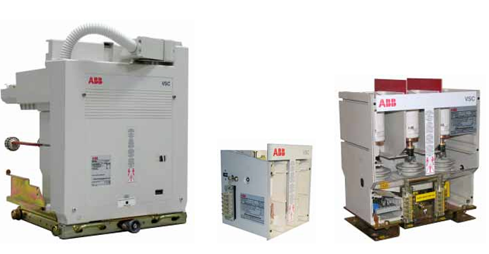
Call us 24/7uaedcs@163.com
Welcome to the official website of CNIACS Automation Technology Co., Ltd!
Call us 24/7uaedcs@163.com

GE MVME51005E Single Board Computer

Specification
Processor type and frequency: MPC7410 or MPC750 processors are available.
Model and Frequency: MPC7410 or MPC750 processors are available with internal clock frequencies of 400MHz or 500MHz for the MPC7410, 450MHz for the MPC750, and bus clocks of up to 100MHz for both processors.
Technical features: The MPC7410 integrates AltiVec™ technology for algorithm-intensive computing tasks, while the MPC750 is a low-power processor suitable for field applications where power consumption is critical.

Storage
On-board memory: The on-board EEPROM is 1MB and is programmable via two 32-pin PLCC/CLCC sockets. 16MB of surface mount Flash memory is also available.
Main memory: PC100 ECC SDRAM with on-board capacity ranging from 32MB to 512MB, expandable to a maximum of 1.5GB with the RAM500 memory mezzanine.
NVRAM: Equipped with 32KB of NVRAM, of which 4KB are free for user use.

Interfaces
Serial Ports: Two 16550-compatible asynchronous serial ports are provided, with COM1 interface connected via the front panel RJ45 connector and COM2 interface routed to the on-board 9-pin connector.
Ethernet ports: There are two Ethernet ports, one of which is fixedly routed to the front panel RJ45 connector, while the other can be flexibly configured via jumpers to be routed to either the front panel RJ45 connector or the P2 connector.
PMC slots: Two 32/64-bit PMC slots are provided to support front panel I/O and P2 rear I/O, which is convenient for expanding functions.
PCI Expansion: Equipped with a PCI expansion connector for connecting PMCSpan to further expand the system performance.

Physical Characteristics
Dimensions: Following the standard 6U VME specification, the height is 233.4mm (9.2 inches), the depth is up to 160mm (6.3 inches), the front panel height is 261.8mm (10.3 inches), the width is 19.8mm (0.8 inches), and the maximum component height is 14.8mm (0.8 inches).
component height of 14.8 mm (0.58 in.).

Electrical Performance
Power Requirements: When using the MVME761 Transition Module, current requirements vary by model at each voltage. Maximum current is between 3.0A and 4.7A at +5V, typical current is between 2.6A and 3.5A; typical current is 8.0mA at +12V; and typical current is 2.0mA at -12V.

Environmental Adaptability
Operating Temperature: Two operating temperature ranges are available, commercial and industrial. Commercial grade is 0°C to 55°C and industrial grade is -20°C to 71°C.
Humidity Range: The device will operate properly in environments with 5% to 90% relative humidity (non-condensing).

Safety Precautions
Emphasis is placed on safety precautions during operation, maintenance and repair of the equipment, such as grounding, avoiding operation in explosive environments, keeping away from live circuits, and proper handling of CRTs and lithium batteries, etc. Violation of these precautions may result in death or injury or damage to the equipment. At the same time, the equipment complies with relevant safety standards and regulations, such as CE certification, RoHS directives, and so on.

Product Overview
The MVME51005E is a high-performance VME single-board computer based on the PowerPlus II architecture, offering a wide range of processor choices and rich functional features such as optimised PCI interfaces and memory controllers, dual Ethernet ports, dual serial ports, a variety of storage configurations and flexible I/O modes, making it suitable for use in a wide range of fields such as military and industrial automation.

Hardware Installation
Prepare related equipment and pay attention to static electricity protection before installation. PMC or SBC mode can be selected by setting jumpers, and the jumper settings are different in different modes. The installation process includes installing PMC module, PMCspan module and mounting MVME5100 into VME chassis, with detailed instructions and precautions for each step.

Device Operation
Describes the functions of the switches, indicators, and connectors of the MVME5100, such as the ABT/RST switch for interrupt and reset, the indicators for system status, and the Ethernet and DEBUG ports for communication. It also describes the system power-up and initialisation process, and the role of the PPCBug firmware in this.

Functional Description
The features of MVME5100 are described in detail, including processor performance, multiple memory types, I/O interfaces, timers, interrupt routing and IDSEL routing. Its powerful processing capability and rich interface resources enable it to meet a variety of application requirements.

RAM500 Memory Expansion Module
The RAM500 module expands system memory with multiple capacity options and supports double-bit error detection and single-bit error correction. Its function, installation method and connector pin assignment are introduced to provide guidance for users to expand memory.

Programming Information
The memory mapping of MVME5100 is introduced, including the memory mapping of processor bus, PCI bus and VMEbus. Programming considerations such as PCI arbitration, interrupt handling, reset sources and byte order issues are also discussed to provide programming guidance for developers.

GE MVME6100 Single-Board Computer

Product Overview: Based on the PowerPC MPC7457 processor and the Marvell MV64360 system controller, the MVME6100 integrates a wide range of hardware features such as ECC-protected DDR DRAM, Flash memory, Ethernet interface, serial ports, and PCI/PMC slots.

Product Specifications
Processor: 1.3 GHz MPC7457 processor with 133 MHz bus clock, integrated L1 and L2 caches, 36-bit address and 64-bit data bus.

Cache: L3 cache bus clocked at 211 MHz, 2MB capacity, using DDR SRAM.

Memory: Flash memory supports 8 – 64MB per bank, with two banks, jumper selectable boot bank, with software and hardware write protections in some areas; system memory supports up to 2GB, using 256Mb or 512Mb devices, supported by the Marvell MV64360 system controller.

Interfaces: Dual 10/100/1000 Ethernet ports, two asynchronous serial ports; two 32/64-bit PMC slots, IEEE P1386 support, PMCspan support; standard 6U VME form factor.

Performance Benefits
Powerful Processing: The 1.3 GHz MPC7457 processor with cache provides fast data processing and computation speeds to efficiently handle complex tasks.
Superior storage function: Large capacity Flash and system memory, combined with write-protection mechanism, meets the needs of data storage and programme operation, and guarantees data security.

Excellent communication capability: Dual Ethernet ports support high-speed network communication, and asynchronous serial port facilitates serial data transmission with external devices.
Good expandability: Multiple PMC slots and PMCspan support make it easy for users to expand system functions according to their needs and adapt to different application scenarios.

Precautions
Safe Operation: The whole operation of the equipment should follow the safety precautions, the equipment must be grounded, it is forbidden to use it in an explosive environment, avoid contacting the electrified circuits, and the replacement of the lithium battery should be operated in accordance with the regulations.

Hardware Maintenance: Non-professionals should not disassemble the equipment cover without authorisation, and when replacing components, the power supply should be disconnected and discharged first to prevent static electricity from damaging the circuits.
Electromagnetic interference: the device will generate, use and radiate electromagnetic energy, installation and use of appropriate EMI protection measures to avoid interference with other equipment or interference from other equipment.

Memory Mapping and Register Operation: Accurate understanding and operation of memory mapping and registers are required during programming to avoid system failure due to misconfiguration. For example, when performing memory read and write operations, ensure that the address and data are correct.

GE MVME5500 Single-Board Computer

Product Overview: MVME5500 is a single board computer based on PowerPC MPC7455 processor and Marvell GT – 64260B host bridge, with rich interfaces and features, user configurable via on-board jumpers, and two I/O modes: PMC and SBC.

Hardware Installation: Hardware configuration is required before installation, by setting the on-board jumpers to select Ethernet mode, boot flash memory bank, bus mode and so on. Pay attention to ESD protection during installation, install the board into the chassis and connect the peripherals according to the steps, and check the hardware and connections after installation.

Powerful processor performance: Adopting 1 GHz MPC7455 processor with high-speed data processing capability, it can meet the demands of complex computing tasks. With 256KB L2 and 2MB L3 cache, and L3 bus frequency up to 200 MHz, it can effectively reduce the data access time and improve the overall system speed, providing strong support for running real-time operating systems, processing large amounts of data and other application scenarios.

Rich storage resources: Onboard 8MB Flash is used for booting, and 32MB extended Flash is used for storing additional data or programmes. For system memory, there are two on-board memory banks, each using 256Mb devices, providing a total of 512MB of memory, and you can also add two banks of 512MB of memory through the expansion connector, supporting a maximum of 1GB of system memory. The memory is equipped with double-bit error detection and single-bit error correction functions, which can guarantee the accuracy of data storage and transmission, and is suitable for applications that require high data reliability.

Various interface configurations: two independent 64-bit PCI interfaces, one of which complies with PCI spec rev 2.1 and the other with PCI spec rev 2.2, with a bus clock frequency of up to 66 MHz, allowing connection to a variety of PCI devices and expanding system functions. One 10/100/1000BaseT Ethernet interface and one 10/100BaseT Ethernet interface are integrated to facilitate high-speed data transmission with the network, which is suitable for network communication, data exchange and other application scenarios. In addition, it is equipped with two asynchronous serial ports, which can be used to connect external devices for serial data communication.

Flexible operating mode selection: By setting the on-board jumpers, it can be switched between PMC mode and SBC mode to suit different application requirements. In SBC mode, IPMC712 or IPMC761 I/O PMC and corresponding transition modules can be used to achieve specific functions; in PMC mode, PMC modules with specific user I/O can be used, providing users with diversified application solutions.

Reliable system design: A variety of reset sources, including power-up, Abort/Reset switches, NVRAM watchdog timer, GT-64260B watchdog timer, system control register bits, and VME bus reset, ensure that the system can be reset in time to ensure system stability under abnormal conditions. Adopting Universe II controller to realise VMEbus interface, it supports various VME settings and can be flexibly configured according to the actual application.

Perfect debugging support: Provide boundary scan header (J18) and COP (Riscwatch) header, which is convenient for developers to carry out hardware debugging and troubleshooting, and help to improve the development efficiency and maintainability of the system.

Good environmental adaptability: Operating temperature range of 0°C to +55°C (forced air-cooled), storage temperature range of -40°C to 70°C, and relative humidity of 5% to 90% (non-condensing) during operation, and 5% to 95% (non-condensing) during non-operation, enabling stable operation in a wide range of environmental conditions. It can withstand non-operating 1 G sine sweeps, horizontal and vertical vibration from 5 to 100 Hz, and meets industry standards for complex environments such as industrial sites.

Control Wave Micro 396563-07-4 CPU33 240mA @ 3.3VDC

CAUTION
When installing units in a hazardous area, make sure all installation components selected are labeled for use in such areas.
Installation and maintenance must be performed only when the area is known to be
non-hazardous.
Installation in a hazardous area could result in personal injury or property damage.
Always turn off the power to the ControlWave Micro before you attempt any type of wiring.
Wiring of powered equipment could result in personal injury or property damage.
To avoid circuit damage when working inside the unit, use appropriate electrostatic
discharge precautions, such as wearing a grounded wrist strap.
Do not open enclosure unless area is known to be non hazardous.
SPECIFICATIONS: ControlWave Micro
POWER
External Power Input: 10.7 to 30 V dc (+12 V dc) or
21.7 to 30 V dc (+24 V dc), depending on configuration of jumpers switches, reverse polarity protection.

SPECIFICATIONS: ControlWave Micro
POWER
External Power Input: 10.7 to 30 V dc (+12 V dc) or
21.7 to 30 V dc (+24 V dc), depending on configuration of jumpers switches, reverse polarity protection.

Input: 10.7 to 30 V dc, 3A max, 36 watts max.
Reference ratings for each device are:
396560-01-6: 2 mA @ 3.3 V dc
396560-02-4: 2 mA @ 3.3 V dc
396563-16-3: 240 mA @ 3.3 V dc
396581-06-4: 145 mA @ 3.3 V dc
396657-02-8: 2A @ 24 V dc
4A @ 12 V dc
396686-01-0: 96 mA @ 120 V ac
40 mA@ 3.3 V dc
396897-02-9: 46 mA @ 3.3 V dc
24.3 mA @ Vext (11-30 V dc)

ENVIRONMENTAL
Operating Ambient Temperature: —40 to +70C.
Storage Temperature: —40 to +85C.
Operating Humidity: 15 to 95%, non-condensing.
WEIGHT ;0.36 kg (4-slot base unit or 4-slot expansion unit).
APPROVALS:ATEX/IECEx

ControlWave Micro Special Conditions for Safe Use
Connections made to RS-232 or RS-485 communications ports shall be mechanically secured in place with suitable screw connections to prevent loosening or disconnection during use.
When using Ethernet connections, the RJ45 (Ethernet) connection must have a mating
connector with a valid securing clip to prevent loosening or disconnection during use.
The USB connector on the IEC 62591 module shall not be used unless the area is known to be nonhazardous (non-flammable).
Install the ControlWave Micro within a suitable certified tool-accessible ATEX or IECEx approved IP54 or better enclosure.
The area in which the equipment is used should be a minimum of Pollution degree 2, as defined by IEC 60664-1 (that is, the environment should not contain conductive pollution and the equipment shall be installed in an indoor or sheltered location).
The equipment may be used in zone 2 with flammable gases.
The equipment may be used in the presence of flammable gases and vapors with apparatus groups IIC or IIB or IIA and with temperature classes T1 or T2 or T3 or T4.

GE 151X1235BC01SA01

GE 151X1235BC01SA01 Gas Turbine Control Systems.

It operates on the QNX Neutrino real-time, multitasking operating system, designed for high-speed, high-reliability industrial applications.

The UCSB controller does not host any application I/O; instead, all I/O networks are attached to each controller, ensuring no single point
of application input is lost if a controller is powered down for maintenance or repair.

This 151X1235BC01SA01 refers to UCSB-CSLA copper module 600, which is a component of the
GE Speedtronic EX2100e controller in the MARK VIe/s series.

This controller is used for functional safety loops to achieve SIL 2 and 3 capabilities, making it suitable for critical safety functions in industrial environments.

The module is a combination of microprocessor-based Universal Controller Independent (UCSB) and compact high-speed Serial Link Extension (CSLA) boards.

Utilizes the QNX Neutrino OS, known for its real-time performance and multitasking capabilities.

The power of modularity

GE Vernova’s HA gas turbine auxiliary systems are pre-configured, factory assembled and tested modules engineered to reduce field connections, piping, and valves.

This translates to a simpler installation that reduces field schedule and installation quality risks while improving overall installation times—up to 25% quicker compared to GE Vernova F-class gas turbine enclosures.

Emissions and flexibility supporting a greener tomorrow

The 9HA’s DLN 2.6e combustion system offers a step change in performance, emissions and fuel flexibility.

The DLN 2.6e maintains many of the elements of GE Vernova’s DLN 2.6+ combustion system and introduces advanced premixing for reduced NOx emissions while enabling high plant efficiency.

Its advanced premixer enables expanded fuel flexibility to operate on both “rich” and “lean” gaseous fuels, a 50% hydrogen (H2) capability with a technology pathway to 100%, a gas turbine turndown to 30% load, and an optional park mode at 7-15% load, further reducing customers’ operating costs.

GE Vernova’s H-class combined-cycle power plant has industry-leading flexibility and full combined-cycle plant load in less than 30 minutes, making it a great complement to intermittent renewable sources.

Whether you’re generating; power for entire cities, electrifying your own operations, or are facing an emergency electricity shortage and need power fast, we can act as a versatile gas turbine supplier, ready to quickly provide a range of solutions.

General Electric | 151X1235BC01SA01 | Ethernet Switch 10-slot

GE 369 Motor Management Relay Instruction Manua

Product Overview

The 369 Motor Management Relay is used for the protection and monitoring of three-phase motors and their mechanical systems, and has a unique ‘learning’ capability to adapt to different motor applications. It offers a variety of optional functions such as RTD monitoring, metering packages, return differential detection, etc. It also has a variety of communication interfaces and supports a wide range of communication protocols, which can be set up and monitored via software .

Performance Advantages
1、Various and flexible functions: It has rich protection and management functions, covering not only basic protection such as overload, short circuit and ground fault, but also various protection functions such as under-voltage, over-voltage, phase sequence reversal, power factor, etc. It supports 12 RTD inputs, and the RTD type can be selected by software. Supporting 12 RTD inputs, it can accurately monitor the temperature of each part of the motor, and the RTD type can be selected by software. It is equipped with various control functions, such as supporting remote start and stop of motor, automatic restart, reduced voltage start control, etc. It can also flexibly configure various functions through the setpoints to meet the needs of different application scenarios.

2, excellent protection performance: the use of advanced protection algorithms and components, its thermal model can take into account a variety of operating conditions and factors of the motor, such as overload curve, unbalance bias, cooling time constant, etc., to effectively protect the motor from overheating damage. In terms of protection against short-circuit and ground faults, it has an adjustable delay and sensitive detection function, which can respond to faults quickly and accurately to avoid serious damage to the motor and equipment. Moreover, there are perfect protection mechanisms for the motor starting process, such as acceleration tripping and startup prohibition, preventing the motor from abnormalities in the starting process.

3, monitoring accurate and comprehensive: can accurately measure and display a variety of electrical parameters, such as phase current, voltage, power, power factor, frequency, etc., but also real-time monitoring of the motor’s operating status, such as motor status, start-stop time, load conditions. It is equipped with event recording and statistics function, which can record up to 512 events, including fault tripping and alarm, etc., which is convenient for users to carry out fault troubleshooting and equipment operation analysis. At the same time, it can analyse the trend of the motor’s operation data to help users find potential problems in advance and optimize the equipment maintenance plan.

Product Specification
Input Specifications
Control power supply: LO (DC 20 – 60V, AC 20 – 48V/50 – 60Hz) and HI (DC 50 – 300V, AC 60 – 265V/50 – 60Hz) ranges, nominal power 20VA, maximum power 65VA, protected by T 3.15 A H 250V (5 x 20mm) fuse.
Current input: phase current CT in 1A and 5A sub-sections, primary 1 – 5000A, 20 – 100Hz; earth current in 1A/5A sub-sections and 50:0.025 types.
Voltage Inputs: Metering option (M) enabled on installation, VT ratio 1.00 – 240.00:1, secondary 240V AC, 20 – 100Hz.
Other Inputs: 6 programmable opto-isolated digital inputs; RTD support 3-wire, multiple sensor types, -40°C to 200°C or -40°F to 392°F; BSD input (B option) frequency 1 – 120Hz, voltage 20mV to 480V RMS.

Output Specifications
Analogue outputs: 1 basic unit, 3 additional for metering options, 0 – 1mA, 0 – 20mA, 4 – 20mA, different loads and accuracies, isolated outputs.
Output relays: 4 Form C relays, 8A (250V AC or 30V DC) for resistive loads and 3.5A (250V AC or 30V DC) for inductive loads.

Metering specifications
A wide range of electrical quantities can be measured under the metering option (M), such as power metering with ± 2% accuracy, event logging, and other functions.

GE MULTILIN 369 QUICK START MANUAL Pdf Download | ManualsLib

GE Grid Solutions 350 Feeder Protection System

Product Overview
The 350 Feeder Protection System is a microprocessor-based relay for primary and backup overcurrent protection of low- and medium-voltage distribution feeders, as well as small- and medium-sized motors, transformers, generators and distribution buses. Featuring small size, extractable, various protection and control functions, and rich communication protocols, it can communicate and integrate with other devices in various ways to facilitate monitoring and control of power systems.

Installation Guide
Mechanical Installation: Introduces the dimensions of the device, product identification, steps and precautions for different mounting methods (standard panel mounting, mounting using an adapter plate), as well as plug-and-play operation of the withdrawable unit, IP20 protective cover mounting, and mounting methods for the arc flash sensor.
Electrical Installation: Covers typical wiring diagrams, terminal identification, wiring ranges, phase sequence and transformer polarity requirements, as well as detailed descriptions of electrical connections for current, voltage, control power, contact inputs, trip and close output relays, serial communications, and more.

Specification Parameters
1, protection function parameters: covering a variety of protection functions, such as overcurrent protection, different types of overcurrent protection (phase overcurrent, ground overcurrent, etc.) with different pickup (Pickup) and dropout levels, time delay and curve settings; undervoltage, overvoltage protection for different types of voltages (phase voltage, neutral voltage, etc.) with the corresponding pickup and dropout voltage settings, time delay can also be adjusted; frequency protection for overfrequency and underfrequency to set a specific pickup frequency and time delay; frequency protection for overfrequency and underfrequency to set a specific pickup frequency and time delay. The undervoltage and overvoltage protection has corresponding pickup and dropout voltage settings for different voltage types (phase voltage, neutral voltage, etc.), and the time delay can also be adjusted. In addition, there are protection functions for special faults, such as phase break detection, power direction protection, etc., each with its own corresponding parameter settings.

2, measurement and metering parameters: can accurately measure a variety of electrical quantities, including current (each phase, neutral, grounding, etc. current), voltage (each phase, neutral, auxiliary voltage, etc.), power (active, reactive, apparent power), energy (positive and negative watt-hour, spent time), power factor, frequency, etc., and each parameter has the corresponding accuracy and range. For example, the three-phase active power measurement accuracy is ±1% of full scale, resolution is 0.1MW, and the range is ±100000.0kW.

3, communication parameters: with a variety of communication interfaces, such as RS485, Ethernet, USB, etc. The RS485 port supports a variety of baud rates and protocols, the Ethernet port supports different connection types and protocols, and can also be configured with parameters such as IP address, subnet mask, etc., in order to meet different communication needs.

4, other parameters: power supply, there are different voltage ranges to choose from; physical characteristics, specify the size and weight of the device; environmental adaptability, specify the operating temperature, altitude, pollution levels and other conditions .

Performance Advantages
1、Comprehensive protection ability: with rich protection functions, it can provide all-round protection against various power failures. Different types of overcurrent protection can effectively deal with overcurrent situations of different degrees and locations; under-voltage and over-voltage protection can safeguard the safety of the equipment in case of voltage abnormalities; frequency protection can prevent system frequency abnormalities from damaging the equipment; and special fault protection functions can detect and deal with special situations such as phase breaks, power direction abnormalities, etc., which greatly improves the safety and stability of the power system.

2, accurate measurement and monitoring: high-precision measurement capability makes the monitoring of power system operation status more accurate. Through real-time monitoring of various electrical quantities, abnormalities in the system can be detected in time, providing a reliable basis for fault diagnosis and prevention, helping to optimise the operation and management of the power system and improve the quality of power supply.

3, flexible communication and configuration: a variety of communication interfaces and rich communication protocols, so that it can be seamlessly connected and communicated with a variety of devices, convenient to achieve remote monitoring and centralised management. Flexible configuration options can be customised according to different application scenarios and needs, improving the applicability and flexibility of the product to meet diversified industrial needs.

4、Reliable operation guarantee: with good environmental adaptability, it can operate stably under different temperatures, altitudes and pollution levels. Perfect self-diagnosis and fault alarm function can timely discover the equipment’s own problems and take corresponding measures to reduce the impact of equipment failure on the power system and ensure the reliable operation of the power system.

Multilin 350 Feeder Protection System :: GE Grid Solutions

GE 269Plus Motor Management Relay

Product Overview: The 269Plus Motor Management Relay is a microprocessor-based relay designed to provide comprehensive and accurate protection for industrial motors and their associated mechanical systems. It can be adapted to a wide range of application scenarios and has a unique ‘learning’ capability that automatically acquires the motor’s starting current, negative sequence current K-factor, cooling rate, starting thermal capacity and acceleration time, etc., so as to flexibly adapt to different motors.

Application areas: mainly used for the protection of three-phase AC motors and their mechanical systems, can ensure the safe and stable operation of motors under a variety of complex working conditions, widely used in various industrial production scenarios, providing strong support for the reliable operation of motors.

Protection Functions: Rich and powerful protection functions covering stator winding overheat, bearing overheat, multiple starts, overload (8 standard overload curves and user-defined FlexCurve™), blocking, fast trip/mechanical blocking, unbalanced/single-phase operation, short-circuit, phase sequence reversal (instrumentation option), ground fault, undercurrent, etc.

The protection functions of the motor include the following: overload protection, overload protection, overload protection, overload protection, overload protection and overload protection. Also, with variable lockout times, the motor can be effectively protected according to the actual situation. Through thermal modelling function, motor It value can be calculated based on the actual motor load current, and thermal capacity calibration can be carried out in combination with RTD temperature monitoring to ensure the accuracy of protection.

Communication Function: Adopting Modbus® RTU protocol, through the RS485 interface located at the rear port of the relay, it can successfully communicate with a variety of PLCs, such as Modicon, Square D, Allen Bradley, and GE Fanuc, etc., which is convenient for remote monitoring and control.

Measurement and Monitoring: A wide range of motor operating parameters can be measured and displayed in real time, such as average and phase-by-phase current, RTD temperature, unbalance rate, ground leakage current, thermal capacity remaining, estimated trip time, motor load percentage, voltage (meter option), power, power factor, frequency (meter option), etc. . Previous alarms can be logged for troubleshooting, displaying the cause of the trip and remaining lockout time for quick troubleshooting and problem solving. The StatTracTM feature also provides statistics on motor usage such as hours run, starts, trips, etc., which can be useful for operation monitoring, maintenance and troubleshooting.

Inputs and Outputs: Inputs include speed switch inputs, differential relay inputs, and backup inputs, which can be flexibly configured as standard or specific contact inputs. For outputs, there are 4 output relay contacts, namely trip relay, alarm output relay (can be set as latching or non-latching), auxiliary 1 output relay (can be set as latching or non-latching) and auxiliary 2 output relay. In addition, there are analogue outputs that can be used to indicate motor thermal capacity, current, hottest stator RTD temperature, bearing RTD temperature or CT secondary current.

Typical Wiring and Selection: Typical wiring diagrams are given in the manual to show how the relay is connected to the motor, CT, RTD, etc. The manual also lists the different versions of the relay. It also lists the selection information of different versions of relays in terms of phase CT, ground CT, relay fail-safe code, relay contact arrangement, control voltage, etc., which makes it convenient for users to select the right model according to actual needs.

269Plus Motor Management Relay

GE 239 MOTOR PROTECTION RELAY

Product Overview: The 239 relay is designed to protect three-phase AC motors with a variety of protection functions and can be connected to a central control/monitoring system. It monitors phase currents, is suitable for motors of various voltages, and has a variety of optional features such as RTD monitoring, analogue outputs, etc. It is certified for use in many industrial environments. The product is certified for use in a variety of industrial environments.

Installation guide: Installation requires cutting holes in the panel according to the size and fixing with screws. Check the product label to confirm configuration and options before installation. External connections include control power, CT inputs, output relays, etc. Different connections have different requirements and require attention to grounding and insulation. There are also specific precautions for performing dielectric strength tests.
Operating instructions: Operation is via the front panel, which consists of keys, display and status indicators. The keys are used to select information, set parameters, etc.; the display can show a variety of information; and the status indicators reflect the operating status of the relay.

Programming settings: Setting points can be input through the front panel, RS485 port and computer or SCADA system connection. The setting content covers system configuration, protection function, output relay and so on, and different setpoints have different functions and value ranges.

Monitoring Function: It can monitor various operating parameters of the motor in real time, such as current, temperature, load, etc.. It can also view fault records, statistical data, etc., which is convenient for evaluating the motor running status and troubleshooting.
Specification Parameters

Current-related parameters: phase current input supports 1A and 5A sub-range, range 0.1 – 11×phase CT primary, accuracy ±2% of full scale; ground current input is divided into 5A sub-range and 50:0.025, with different accuracy for different ranges. There are 15 types of overload curves, overload pickup suppression 1.00 – 5.00 x FLC, pickup level 1 – 1500A. Short-circuit and earth tripping, circuit breaker failure, etc. have corresponding current setting ranges and time delay settings.

Other electrical parameters: Support multiple voltage control power supply, 90 – 300VDC/70 – 265VAC is standard, 20 – 60VDC/20 – 48VAC (MOD 501) is also optional. Communication interface is RS485, 2-wire half-duplex isolated, baud rate 1200 – 19.2kbps, Modbus RTU protocol. Analogue output can be selected from 0 – 1mA, 0 – 20mA, 4 – 20mA, different ranges correspond to different load capacity, accuracy ±2% of full scale reading.

Advantages
Comprehensive protection: It provides all-round protection for the motor, covering overload, short-circuit, blocking, under-current, unbalance, ground fault, overheating and other types of faults. For example, in overload protection, 15 optional curves can accurately match the thermal characteristics of the motor, effectively avoiding damage to the motor due to overload.

Convenient communication and monitoring: Equipped with RS485 communication interface, it can be connected to the central control/monitoring system to achieve remote monitoring, set point programming and fault diagnosis. At the same time, it can monitor various parameters of the motor in real time, such as current, temperature, running time, etc., which is convenient for the operator to grasp the running status of the motor in time.

Strong adaptability: it can be adapted to motors with various line voltages, and protection is achieved by monitoring the phase current through the current transformer. A variety of control power supply options, wide temperature operating range and high altitude adaptability, so that it can work stably in different industrial environments.

ABB 1TGE106170M4200

ABB 1TGE106170M4200
Integrated intelligence to the core
The design of MNS iS incorporated fully segregated power and control cable compartment for independent access.
The withdrawable units are incorporates equipped with the smart sensor technology for measuring current, voltage and contact temperature.
Control and protection components, installed separately from electrical circuits, are connected to the data concentrator,
that collects all switchgear and starter/feeder information and distributes right information to right operator.
This means process related information is sent to Process Operator and electrical oriented information to electrical operator in real time.
Information to electrical operator can also be offered based on condition monitoring so that the plant electrical staff can operate
the switchgear with ease and can maintain the switchgear in top condition- tackling the day to day situation proactively.

Main benefits
Unmatched safety for the protection of personnel and plant
Reliable, flexible and scalable
Easy to and fast to maintain
Reduced footprint due to the most compact module size
Switchgear real time ‘Condition Monitoring’ functionality to support pro-active maintenance
Increased plant availability

Main features
Standard power modules to reduce module and stock variants as well as minimize Mean-Time-To-Repair (MTTR)
Flexible control modules to support wide range of applications and provide easy configuration of process related interlockings
Integrated control schematics for easy configuration
Main contact including a high precision shunt that measures current, voltage and temperature offering detailed system information
Flexible communication and user interfaces support easy integration, operation and web based navigation

Application Fields
Food and beverage processing industry: In the production line of food and beverage, various motors drive the mixer, conveyor belt, filling machine, etc. 1TGE106170M4200 can reliably start these motors to ensure the stable operation of the production process, and ensure the quality and efficiency of food and beverage production. For example, in the beverage filling process, the stable start and operation of the motor is directly related to the accuracy and speed of filling.

Material handling field: Whether it is material transfer within the factory, or goods handling in the logistics warehouse, it is indispensable for motor-driven forklifts, cranes, conveyors and other equipment. The starter can be adapted to the working requirements of different material handling equipments, realising efficient starting and reliable operation of the motor, and enhancing the efficiency and safety of material handling.

Automobile manufacturing industry: In the process of automobile manufacturing, a large number of motors in the automated production line need to be accurately controlled to start.1TGE106170M4200 can meet the requirements of automobile manufacturing enterprises for high reliability and high performance of motor starter equipment, from the processing of parts and components to the assembly of the whole vehicle, to ensure the smooth progress of each production link.

Search for products

Back to Top
Product has been added to your cart